Requires: Utmost IV, SmartSpice, SmartView
Minimum Versions: Utmost IV 1.10.6.R, SmartSpice 4.10.6.R, SmartView 2.28.2.R
In order to perform measurements using real instruments, it is necessary to define
how the measurement instruments are connected to the device being measured. This
example describes how to set up your device connections for DC measurements.
The project file
acq_ex08.prj
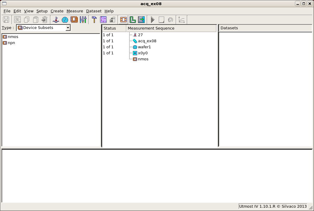
for this example should be loaded into your database. When opened, the
project will look as shown in
acq_ex08_01.png
. This acquisition project is in measurement mode, which enables the project
Hardware
and
Connections
.
To measure your device, you will have to define how the device is connected to
the hardware. This is done in the connections dialog. When a new device type
is created, a default connection is created at the same time for this new device
type in the connections dialog.
If you open the connections dialog by selecting
Setup->Connections
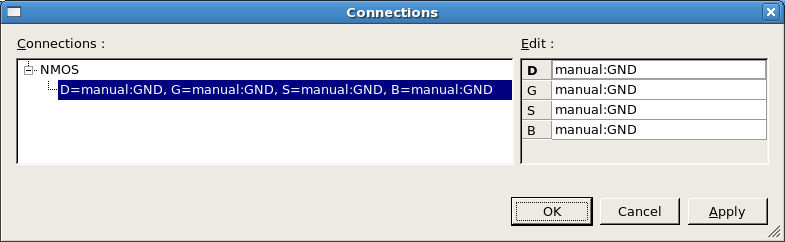
from the menu, you will see that the project already has a default connection
defined for the ‘NMOS’ device type. However, the only measurement unit available
is ‘manual:GND’ as you can see from
acq_ex08_02.png
. This is because the DC Analyzer has not been enabled yet in
the Hardware.
Close the connections dialog and open the hardware dialog by selecting
Setup->Hardware
from the menu. Now you should edit the DC Analyzer, enable the
instrument and select the agilent_hp_4156c driver file. Save and exit
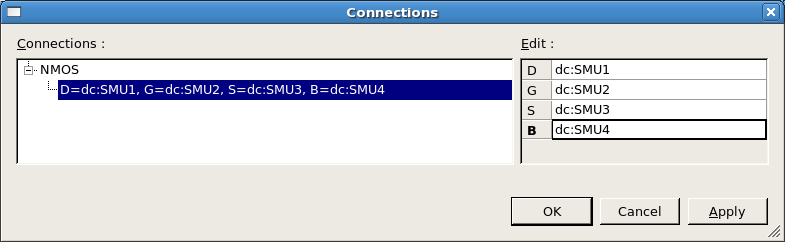
the hardware dialog and re-open the connections dialog. Now you can
select the measurement units from the agilent_hp_4156c instrument in
the connections dialog as shown in
acq_ex08_03.png
.
A device subset containing the nmos transistor is already present in the
measurement sequence. You now need to add the ‘IdVg’ measurement setup
into the sequence. Note that this does not create an additional connection
since it matches the default connection for this device type with all
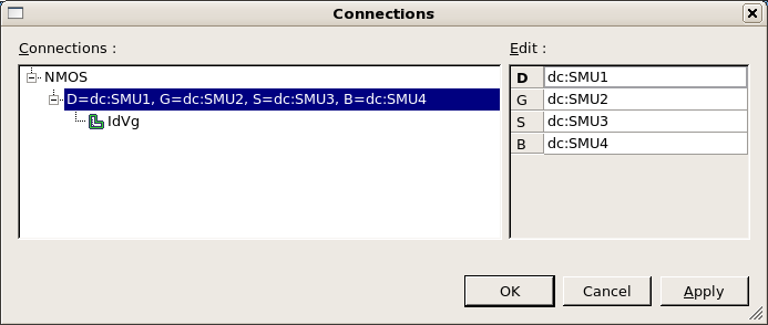
nodes separately connected in the measurement setup. If you open
the connections dialog again, you will see that the ‘IdVg’ measurement
setup is shown under the default connection for the ‘NMOS’ device type
as shown in
acq_ex08_04.png
.
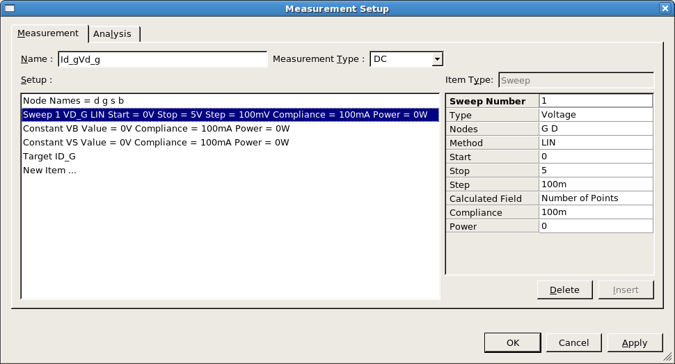
Also present in the project is a measurement setup called ‘Id_gVd_g’
which is shown in
acq_ex08_05.png
. In this measurement setup the D and G nodes are connected together.
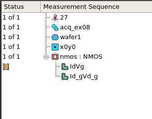
Now you should add this measurement setup into the sequence as shown
in
acq_ex08_06.png
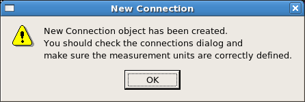
. When you do this a pop up message, as shown in
acq_ex08_07.png
, will appear to remind you that
a new connection has been made for this measurement as it does not
match to the existing connection.
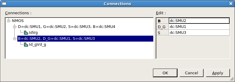
Now re-open the connections dialog and you can define how the
measurement hardware will be connected for this new measurement
as shown in
acq_ex08_08.png
.
Each device type that you create has its own set of connections.
Now we will add a new device type for an npn transistor measurement.
Select
Setup->Devices
from the menu to open the device type manager dialog and select
New
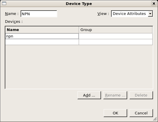
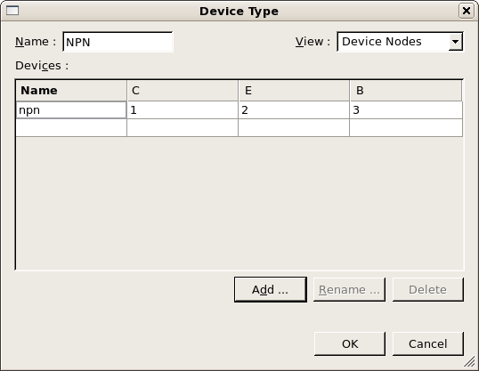
to create a new device type. This device type will be called ‘NPN’, the
Device Attributes
should be as shown in
acq_ex08_09.png
and the
Device Nodes
should be as shown in
acq_ex08_10.png
. Once you have finished creating this new device type, again the pop up message
will appear to let you know that a new connection has been created.
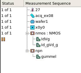
Add in the ‘npn’ device subset and the ‘gummel’ measurement setup into the
measurement sequence as shown in
acq_ex08_11.png
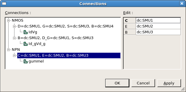
. Now if you open the connections dialog you can define how the measurement hardware
is to be connected for this new device type as shown in
acq_ex08_12.png
.
Graphics