Victory Device
Home » Products & Workflows Hub » AI-Driven Manufacturing » TCAD » Victory Device
Victory Device: 2D and 3D semiconductor device simulation
Device simulation that shows you how a transistor, diode or sensor will switch, break down, heat up and respond to light while the design is still a file you can change.
What Victory Device does
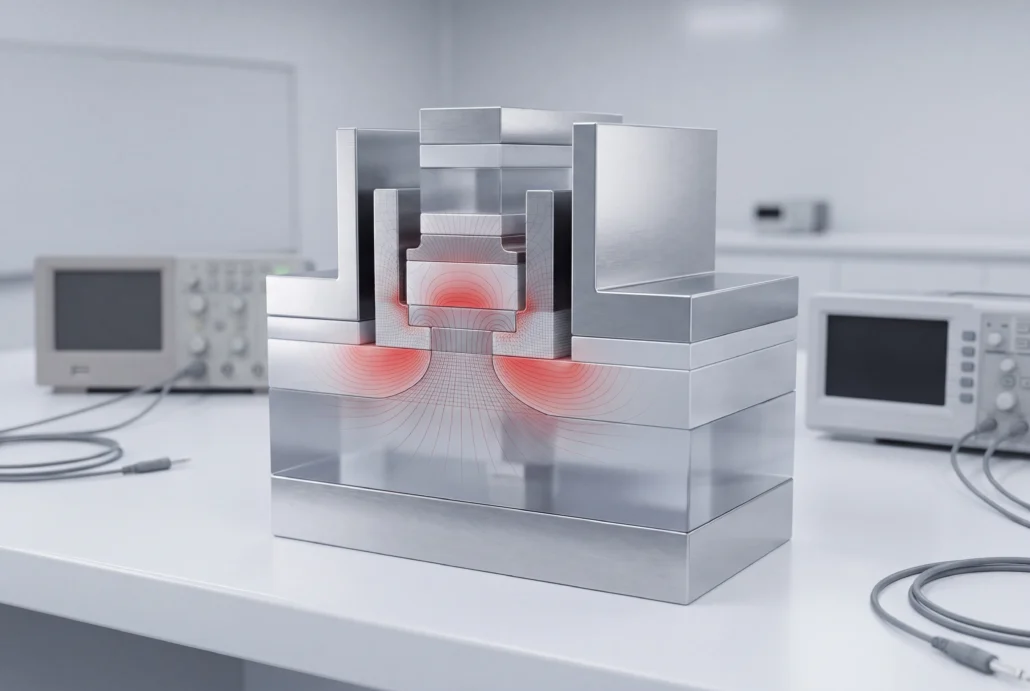
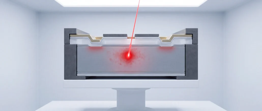
Victory Device is a general-purpose 2D and 3D device simulator that predicts the electrical, thermal and optical behavior of a semiconductor device from its physical structure. You give it the structure. It solves the transport physics. Out come the numbers you’d normally get from silicon: IV and CV characteristics, breakdown voltage, switching behavior. Use it to tune a device, find out why one failed, or check that a design holds up on a new node.
Device simulation capabilities
Core simulator
Drift-diffusion and energy-balance transport in 2D or 3D. DC, AC and transient analysis all run on the same device model, so your bias sweep and your switching transient rest on identical physics. Tetrahedral meshing, with Voronoi discretization for Delaunay meshes, carries the device’s real 3D shape into the solve.
Physics
An editable material database covers silicon and compound semiconductors, and stress-dependent models for mobility and bandgap handle strained structures. Need a model that isn’t there? Write it yourself in the C-Interpreter or load it as a dynamically linked library.
Solver
A multi-threaded numerical library, with distributed computing for 3D jobs too large for one machine. You set arithmetic precision per run at 64, 80, 128, 160, 256 or 320 bits, sized to the question you’re asking.
Modules for heat, light, circuits, radiation and chemistry
Each one works alongside the core simulator and adds another physics domain to the same device.
Giga (self-heating)
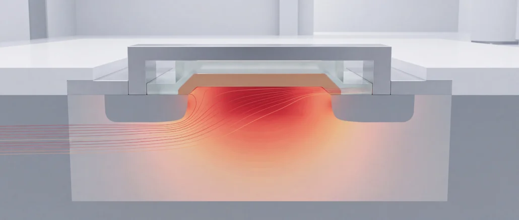
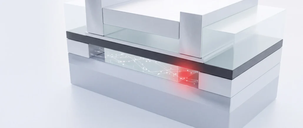
Giga calculates the device’s local temperature at the same time as its electrical behavior. Heat is generated, flows through the lattice and drains into heat sinks, while the material parameters that depend on temperature update as it moves. Most power devices run hot enough for that coupling to matter in everyday operation.
Luminous (optics)
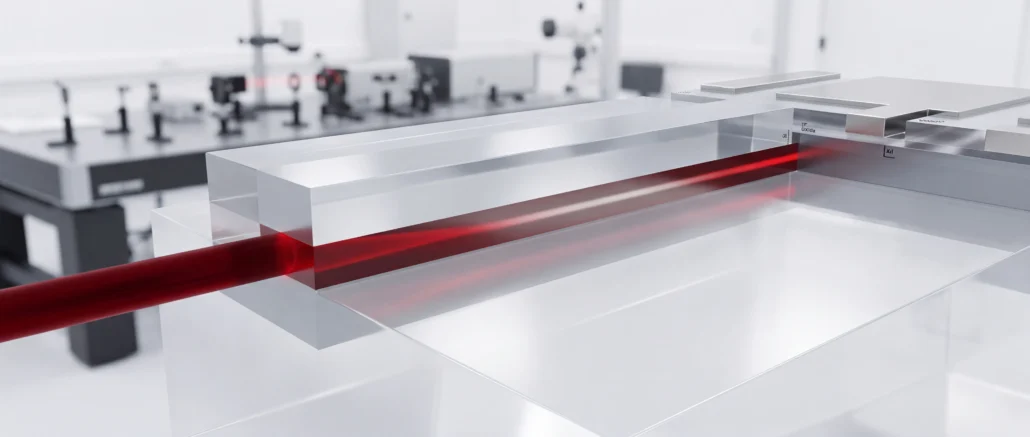
Luminous traces light into non-planar devices of any shape, in 2D or 3D. It works out where that light is absorbed and how much photocurrent it generates. It accounts for reflection and refraction inside and outside the device, polarization and dispersion, with one wavelength or a full spectrum. Results come back as DC, AC, transient and spectral responses, with parameter extraction built for optoelectronics.
Frequency domain: ray trace, transfer matrix, mode solver, beam propagation. Time domain: ray trace, FDTD.
MixedMode (circuit co-simulation)
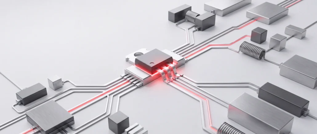
MixedMode drops one or more physics-based 2D or 3D devices into a SPICE netlist and solves the circuit and the devices together. The rest of the netlist uses industry-standard compact models, Verilog-A and ordinary passive elements, parasitic resistance, capacitance and inductance included. Reach for it when a device has no trustworthy compact model yet. It also fits the case where one critical device needs more accuracy than a compact model can give.
Radiation Effects (REM and SEE)
The Radiation Effects Module covers total dose in insulators, single event effects, dose rate effects and displacement damage. The charge a single event deposits depends on photocurrent density and linear energy transfer. Displacement damage runs through a non-ionizing energy loss model, or through lattice-defect layers you define yourself. If the built-in physics falls short, C-Interpreter routines let you prototype your own photogeneration, recombination and charge-trapping models.
Electro-Chemistry
This module tracks electrochemical reactions and the transport of as many chemical species as your problem needs, alongside the device simulation. Use it for hydrogen transport in reliability studies, including bias stress and radiation exposure. It also covers resistive memory such as CBRAM and OxRAM, and ionic transport in batteries and semiconductor-based ionic sensors.
Where it sits in the TCAD flow
It takes its structure from Victory Process, or from Victory Mesh when an existing structure needs refining.
The characteristics it returns feed three next steps: compact models, parameter sweeps and surrogate models.
In
Victory Process or Victory Mesh
The device structure
The devices it's built for
Optoelectronics
CCD and CMOS image sensors, avalanche and PiN photodiodes, solar cells
Published work built on Victory Device
A foundry, a university and a power semiconductor maker, each working on its own device.
SURGE 2026 session
Using Victory 3D Simulation in 375V Partial SOI SJ LDNMOS Breakdown Voltage Study
At 375 V, X-FAB's 2D termination structures stopped being enough. The team designed a 3D termination and split the device into sub-domains, then merged and re-meshed them for a full 3D device simulation. The optimized termination reached 460 V breakdown.
Dr. Elizabeth Kho Ching Tee, Member of Technical Staff in High Voltage Process Development team, X-FAB
SURGE 2026 session
Advanced Logic FinFET/Nanosheet Simulation with Silvaco Victory Tools
Sub-3 nm gate-all-around nanosheets and FinFETs, modeled with quantum confinement, band structure corrections, strain and mobility degradation. Read it for the calibration: how the Victory Device results were checked against experimental data.
Zhenhua Wu, Professor, Zhejiang University
Simulation Standard
June 2026
TCAD Breakdown Simulation of a 1200 V Vertical GaN FinFET
A vertical GaN FinFET taken through the whole flow: process in Victory Process, mesh in Victory Mesh, electrical behavior in Victory Device. The paper names every model it used: Shockley–Read–Hall and Auger recombination, band-to-band and Schottky tunneling, impact ionization, and self-heating.
Khaled Ahmeda, Nereus Agbo and Xiang Li, Dynex Semiconductor
Victory Device resources
Product brief
Product brief
Presentation
Your next step with Victory Device
Evaluating it
Send the structure and the measurement you want to reproduce, whether that's a breakdown curve or a spectral response. A Silvaco application engineer builds the run from your data, so the first result you see comes from your own device.
Already running it
Installers, user manuals and module documentation are all in Support and Downloads.
Stuck on something
Open a case in the support portal and track it there until it's closed. Access comes with a current maintenance contract.
Questions about Victory Device
What does Victory Device simulate?
Device simulation predicts what a semiconductor structure will do before anyone builds it. Victory Device handles that in 2D and 3D, solving drift-diffusion and energy-balance transport for DC, AC and transient behavior. Modules extend it to self-heating, light absorption, SPICE co-simulation, radiation damage and electrochemistry.
What replaced Atlas?
Atlas is retired. Victory Device is Silvaco's current simulator for 2D and 3D device work, and it's Atlas legacy-compatible. Before you move an established Atlas project, talk to our Technical Experts about the structures and physics models it depends on. They'll check each one against Victory Device first.
What are Giga, Luminous and MixedMode?
Three of the modules that run with the Victory Device core simulator. Giga solves self-heating in the same pass as the device physics. Luminous adds light absorption and photogeneration, solved with five methods that run from ray trace to FDTD. MixedMode co-simulates physics-based TCAD devices with the rest of a SPICE circuit.
Can Victory Device simulate self-heating in power devices?
Yes. Giga, one of the Victory Device modules, couples the thermal problem to the electrical one. Heat is generated in the device, conducted through the lattice and removed by heat sinks, while material parameters follow the local temperature. So the electrical result reflects how hot your device actually runs under load.
Can I put a TCAD device inside a SPICE circuit?
Yes, with the MixedMode module. You place one or more 2D or 3D TCAD devices in a SPICE netlist alongside compact models and Verilog-A. That lets a circuit designer test against a device still in development, before anyone has fitted a compact model to it.
How is Victory Device used with Utmost IV to build compact models?
Victory Device simulates the IV and CV characteristics, and Utmost IV extracts a SPICE compact model from those curves. Your circuit team gets a model to design against before silicon exists. Once wafers come back, the same extraction runs on measured data in Utmost IV.