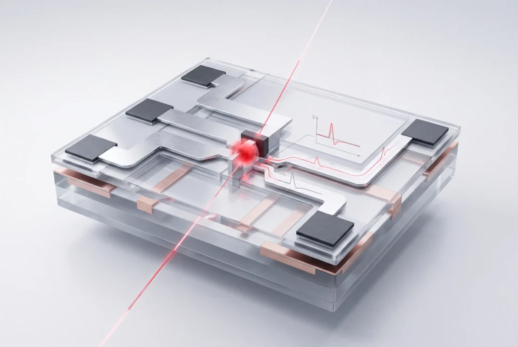
SmartSpice RadHard adds radiation effects circuit simulation to SmartSpice. One .RAD statement brings single event effects and dose rate into your transient and DC analysis. Your netlist stays exactly as it is. The radiation physics is compiled into the standard device models themselves, not bolted on as subcircuits. So an upset shows up in the same waveforms you already read.
Capabilities
Radiation analysis
Call up dose rate or single event effects in transient or DC analysis with a .RAD statement. It names the device, the node and the strike’s linear energy transfer (LET). Single-bit and multi-bit upsets come out of the same run.
Models
Dose rate runs on modified Wirth and Rogers models; single event and multi-bit upsets run on modified Messenger models. Customer-defined models can replace either. You also get to shape the current pulse a strike injects and the photocurrent a dose-rate pulse drives.
Foundry compatibility
Use the HSPICE, PSPICE or SmartSpice models your foundry already ships, across bulk CMOS, SOI, bipolar and BiCMOS processes. RadHard also sits inside Silvaco’s PDK-based design flow for analog, mixed-signal and RF work.
Extension
The Verilog-A option gives you an open model development environment and room for analog behavioral modeling. Studying a radiation effect no standard model covers yet? Custom models and what-if control in the simulator let you test the idea first.
Optimization
Point circuit optimization at radiation tolerance. Each hardening choice shows its cost in design margin, set against the system specification you still have to meet.
Works with
Takes in
A SmartSpice netlist and your foundry models. Bring an HSPICE netlist with W-element RLGC matrix files, S-parameter model files, Verilog-A and AMS blocks, and C/C++ where you need it, plus technology-dependent parameters for dose rate. Device-level results from TCAD come in as I-V curves. Silvaco’s own 22nm 6T SRAM upset case takes its transistor models from 3D Victory Device simulation.
SmartSpice: the simulator RadHard is built on, reading the same netlist and models
Hands off to
SmartView, and the Silvaco radiation flow. Raw files, output listings, analysis results, measurement data and waveforms go to SmartView for analysis. They move between Unix and Windows unchanged. RadHard is also one step in Silvaco’s radiation tool flow. That flow runs from process modeling and device simulation through circuit analysis to physical layout and chip parasitics. Every level of your radiation and reliability check rests on physics.
Circuits that have to keep working under radiation, checked on your foundry's models before any part goes near a test beam.
Single event upset and multi-bit upset analysis
Particle strikes on SRAM cells, flip-flops and latches, from one flipped bit to several at once.
Dose rate analysis
Photocurrents from a dose-rate pulse, across the whole circuit at once. Silvaco has checked simulated dose-rate response on an octal buffer/driver against experimental data.
Radiation tolerance trade-off studies
Compare hardening options side by side and keep the one that meets the specification with margin to spare.
Proof and resources
Customer case study
August 2018
SmartSpice RadHard product brief
Worked examples with the numbers attached: a SiGe D flip-flop struck at LETs of 10 and 20 after total dose, a 6T SRAM cell on 22nm Victory Device models that upsets at an LET of 0.5 MeV-cm²/mg, single event transients broadening at 180, 130 and 65nm, and an octal buffer/driver simulated against experimental dose-rate data.
Download the product brief
SmartSpice RadHard documentation · SPICE simulation published papers · SPICE simulation white papers
Run it on the circuit you have to harden
Pick the cell or block, and the strike or dose-rate condition it has to ride through. You’ll see the analysis on your own foundry models. The first upset you meet is in a waveform, not a test report.
Radiation effects circuit simulation shows how a circuit behaves when radiation reaches it. That might be one particle strike leaving charge at a single node, or a dose-rate pulse driving photocurrents everywhere at once. SmartSpice RadHard runs both inside a SmartSpice simulation on your foundry's device models, and the upset appears right in the waveform.
What is the difference between single event effects and dose rate?
A single event effect starts with one particle hitting one spot. The charge it leaves can flip a memory cell or latch, or several at once in a multi-bit upset. Dose rate is ionizing radiation reaching the entire circuit in one pulse, generating photocurrents in every junction, and SmartSpice RadHard models both.
Does SmartSpice RadHard need a special netlist?
No. Radiation behavior lives in enhanced, compiled versions of the standard device models, so nothing goes into your netlist as a subcircuit. You insert one .RAD statement and run transient or DC analysis on the netlist you already have, with every device and connection left where it was.
Which radiation models are included?
Two families ship with it. Modified Wirth and Rogers models cover dose rate, and modified Messenger models cover single event upsets and multi-bit upsets. If your group has already characterized its own radiation response, swap in a customer-defined model for either family and simulate against that.
Can I add my own radiation models?
Yes. Dose rate and single event upsets both accept customer-defined models, and you can shape the strike current pulse and the dose-rate photocurrent yourself. For behavioral models, the Verilog-A option adds an open model development environment inside the simulator, alongside the built-in radiation models.
Which foundry model formats are supported?
Three: HSPICE, PSPICE and SmartSpice, as foundries supply them for bulk CMOS, SOI, bipolar and BiCMOS processes. The radiation physics is layered onto those models instead of replacing them, so your hardened design runs on the same model set as the rest of your SmartSpice flow.