Requires: Utmost IV, SmartSpice, SmartView
Minimum Versions: Utmost IV 1.10.6.R, SmartSpice 4.10.6.R, SmartView 2.28.2.R
A standard MOSFET device will have four terminals (drain, gate, source and
body). However, many MOSFET devices only have three terminals and do not have
a separate body contact. This example describes how to measure a three
terminal MOSFET. For demo purposes, the example will acquire the dataset
using simulation mode, rather than using measurement mode.
The project file
acq_ex05.prj
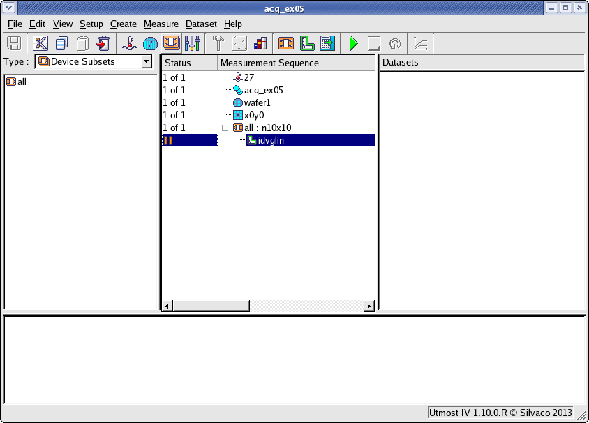
for this example should be loaded into your database. When opened, the
project will look as shown in
acq_ex05_01.png
.
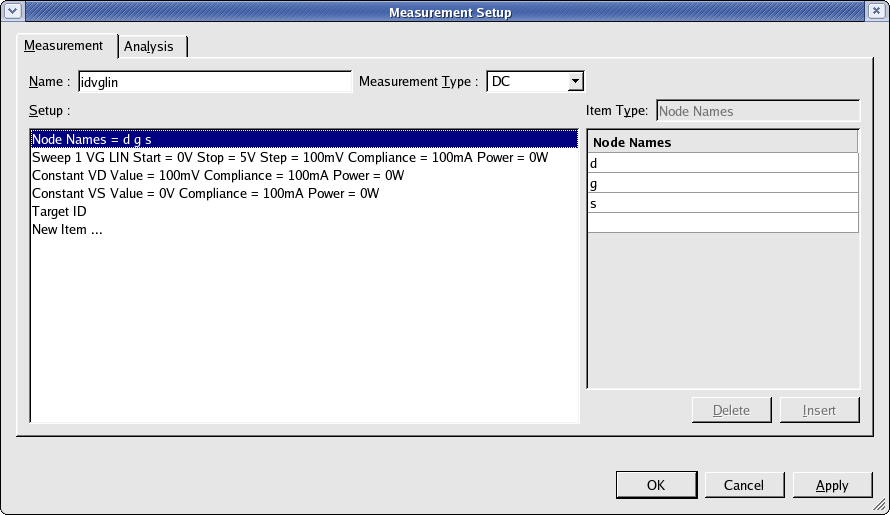
The project contains a measurement setup called idvglin which is shown in
acq_ex05_02.png
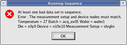
. This setup was defined with only three nodes (d, g and s). If you try to
run the measurement sequence of this project, then an error will occur and
an error message will appear as shown in
acq_ex05_03.png
. The error message says that the nodes in the measurement setup do not match
to the nodes in the device. Since the measurement setup has the correct number
of nodes, then you need to change the device nodes to match.
The device can be modified by selecting the
Setup->Devices
menu item and editing the ‘nmos’ device type. You then select the
Device Nodes
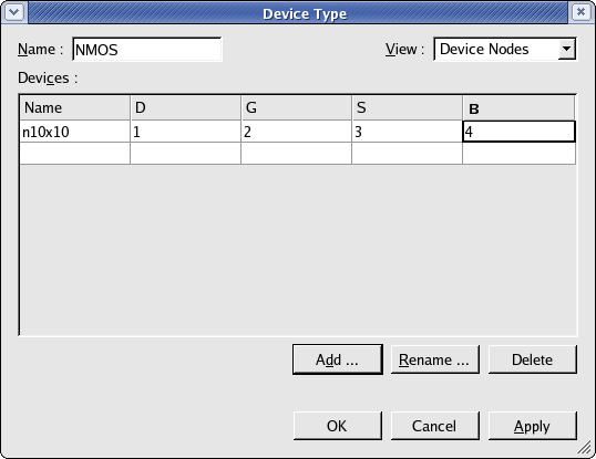
and here you can see that the device was defined with four nodes (D, G, S
and B) as shown in
acq_ex05_04.png
. Note that the node names are case insensitive.
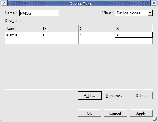
You should click on the ‘B’ node column and delete it as shown in
acq_ex05_05.png
. Now the device nodes and the measurement setup nodes both match.
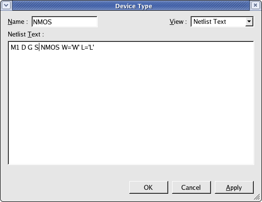
As we are using simulation in this example, you also have to adjust the
Netlist Text
to remove the body node from the SmartSpice simulation as shown in
acq_ex05_06.png
. Now the device nodes, the measurement setup nodes and the simulation
nodes are all in agreement.
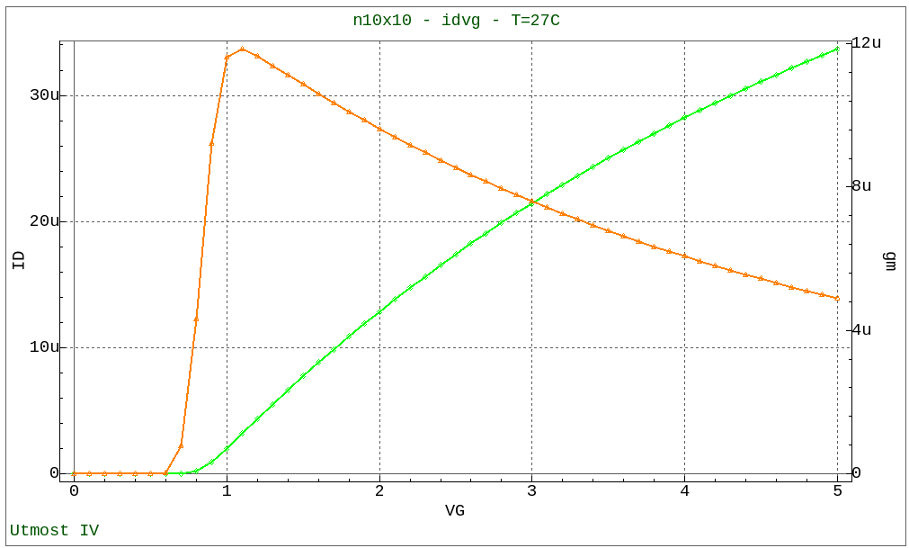
When you run the measurement sequence, this will generate the measured
data as shown in
acq_ex05_07.png
and this will automatically be stored into the database.
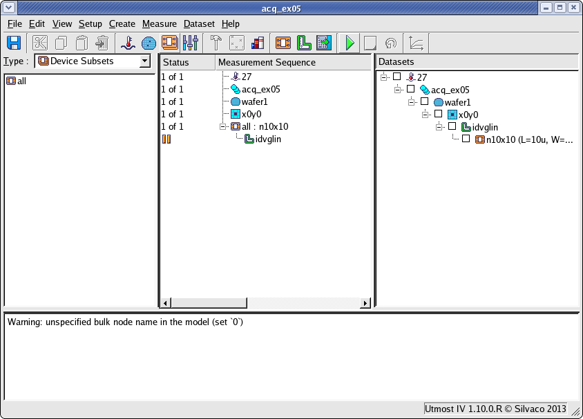
When this dataset is simulated, a warning message is generated in SmartSpice.
This warning message lets you know that the body or bulk node has not been
specified in the simulation. All warning and error messages from SmartSpice
are shown in the Utmost IV status log area as shown in
acq_ex05_08.png
.
Graphics