Requires: Utmost IV, SmartSpice, SmartView
Minimum Versions: Utmost IV 1.10.6.R, SmartSpice 4.10.6.R, SmartView 2.28.2.R
This example describes how to measure a dataset using a linear sweep.
For demo purposes, the example will measure or more correctly acquire
the dataset using simulation mode, rather than using measurement mode.
The project file
acq_ex01.prj
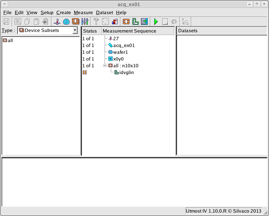
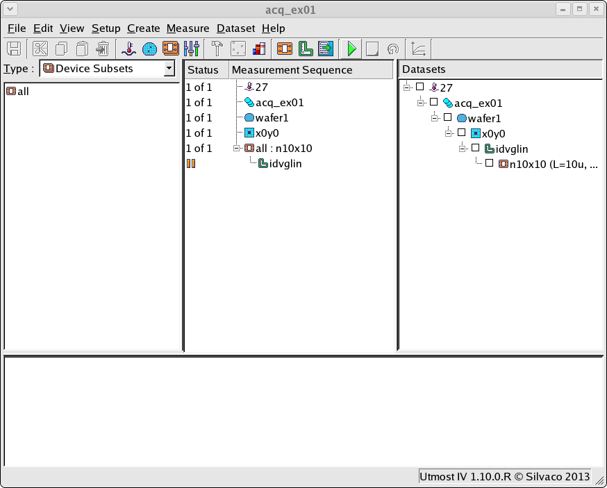
for this example should be loaded into your database. When opened, the
project will look as shown in
acq_ex01_01.png
.
The first thing that must be done is to define the device we are going
to measure. Selecting the
Setup->Devices
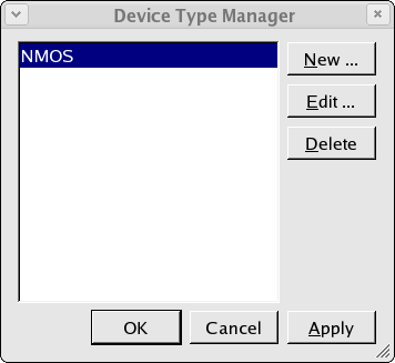
menu item will open up the device type manager dialog as shown in
acq_ex01_02.png
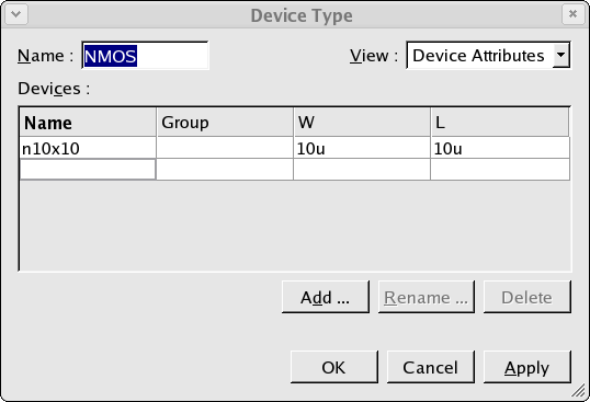
. In the example we have defined one device type called ‘NMOS’. Editing
this device type reveals that this device type contains a single device
called ‘n10x10’ with W and L attribute values of 10e-6 as shown in
acq_ex01_03.png
.
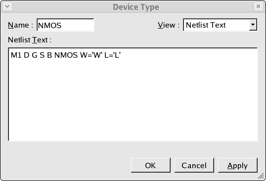
The device type definition also contains the netlist text which is used
when acquiring the datasets by simulation as shown in
acq_ex01_04.png
. Note that the name of the model in this netlist text is ‘NMOS’.
As this example will acquire the dataset by simulation, a spice model must
be defined. Selecting the
Setup->Model Library
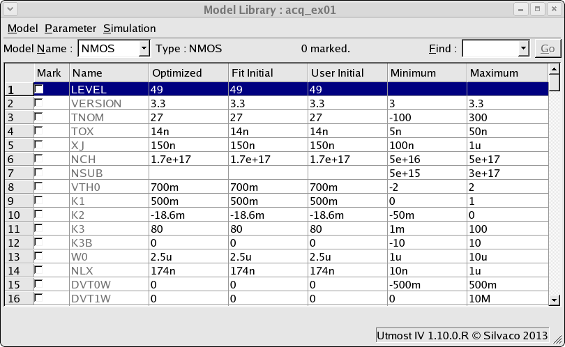
menu item will open up the model library window as show in
acq_ex01_05.png
. A single BSIM3 MOSFET model has been added to the model library with the
name ‘NMOS’in order to match the model name which was defined in the devices
simulation netlist.
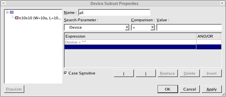
Once we have defined the device to be measured, we need to select this device
and add it to the measurement sequence. This is done by creating a device
subset as shown in
acq_ex01_06.png
. In this device subset, all of the defined devices are selected.
Once the device has been defined and added into the measurement sequence, we
need to define the measurement that is to be performed on this device. This is
done by creating a measurement setup as shown in
acq_ex01_07.png
. Note that this measurement setup has the same nodes as the device we are
going to measure. This measurement setup is a DC type and defines the voltages
and currents which will be applied to the device during the measurement. It also
defines what will be measured on the device. The measurement setup also allows
functions to be performed on the data and plots to be added as shown in
acq_ex01_08.png
.
Once the measurement setup has been defined, this can be added into the
measurement sequence as the child of the device subset. When the measurement
sequence is run, the measurement defined by the measurement setup will be
performed on each device in the device subset.
The measurement is performed by selecting
Measure->Run
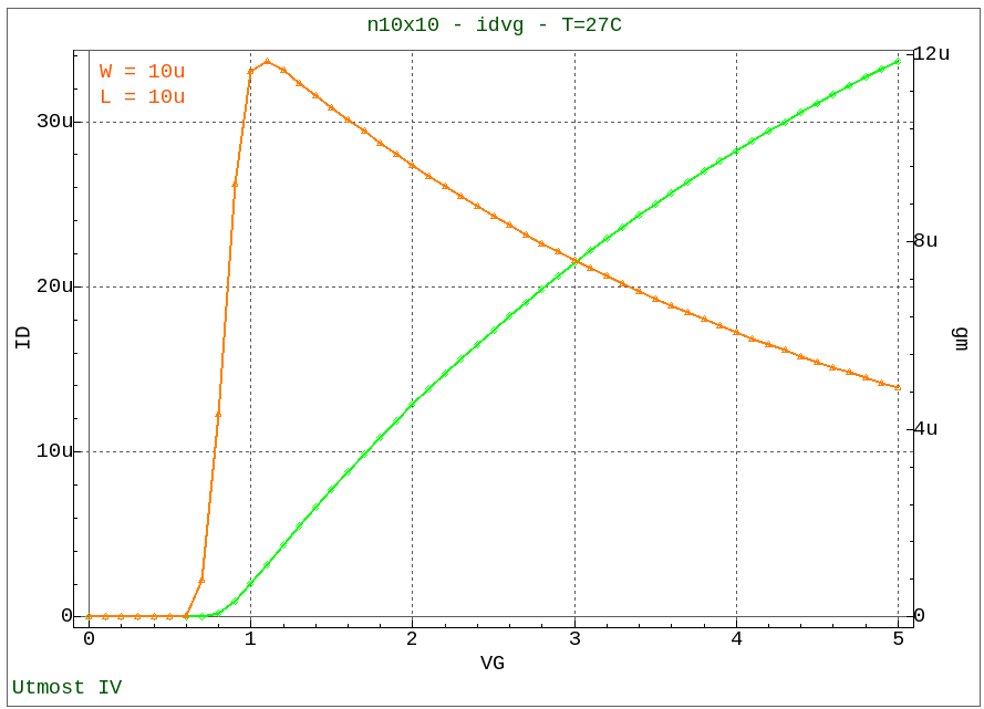
in order to run the measurement sequence. When each measurement is completed,
the results will be displayed in the viewer as shown in
acq_ex01_09.png
and will also be automatically stored into the Utmost IV database. Any datasets
which have already been measured and which are already stored in the database
will be visible in the dataset selector area as shown in
acq_ex01_10.png
.
Graphics