Requires: Utmost IV, SmartSpice, SmartView
Minimum Versions: Utmost IV 1.10.6.R, SmartSpice 4.10.6.R, SmartView 2.28.2.R
This example describes how to perform a bipolar forward active gummel plot measurement with either
constant Vce or constant Vbc. For demo purposes, the example will measure or more correctly acquire
the dataset using simulation mode, rather than using measurement mode.
The project file
acq_ex06.prj
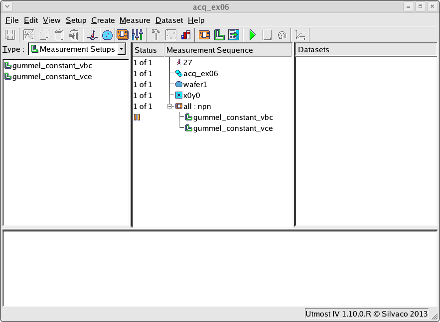
for this example should be loaded into your database. When opened, the
project will look as shown in
acq_ex06_01.png
.
There are two commonly used methods to perform a forward gummel plot measurement for a bipolar transistor.
Both methods ground the emitter and sweep the emitter-base junction in forward bias, but have different
methods of providing the reverse bias on the base-collector junction.
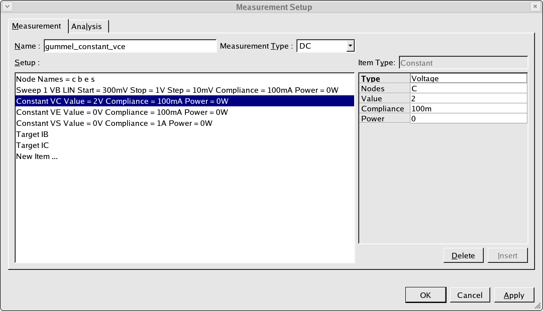
The first method is known as the constant Vce method. In this measurement a constant voltage
is applied to the collector of the transistor as shown in
acq_ex06_02.png
. As both the collector and the emitter voltage are constant values, then the voltage between
the collector and emitter is constant. This is why this is called the constant Vce method.
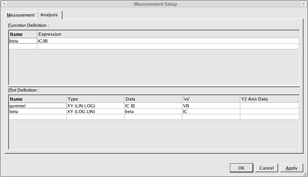
The analysis page of the measurement setup is shown in
acq_ex06_03.png
. Here we calculate the forward current gain (beta) as the ratio of the measured collector and
base currents. We also define two plots. The gummel plot shows the log of the collector and
base currents plotted against the base voltage. The forward current gain plot shows the current
gain plotted against the log of the collector current.
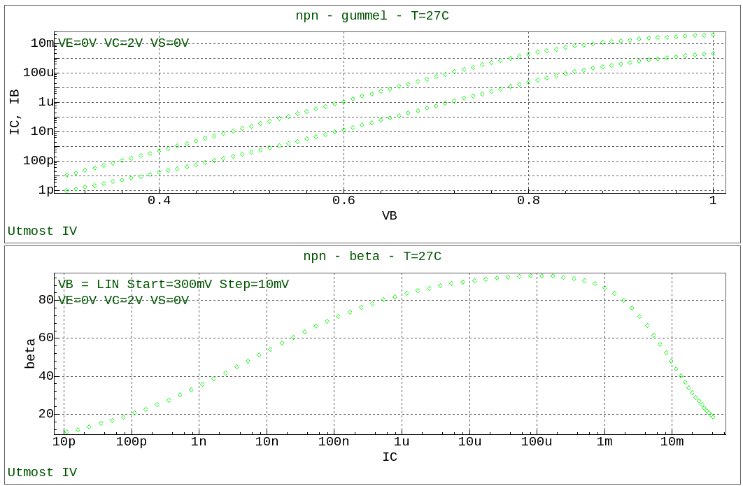
When the measurement is completed, the result will be displayed in the viewer as shown in
acq_ex06_04.png
.
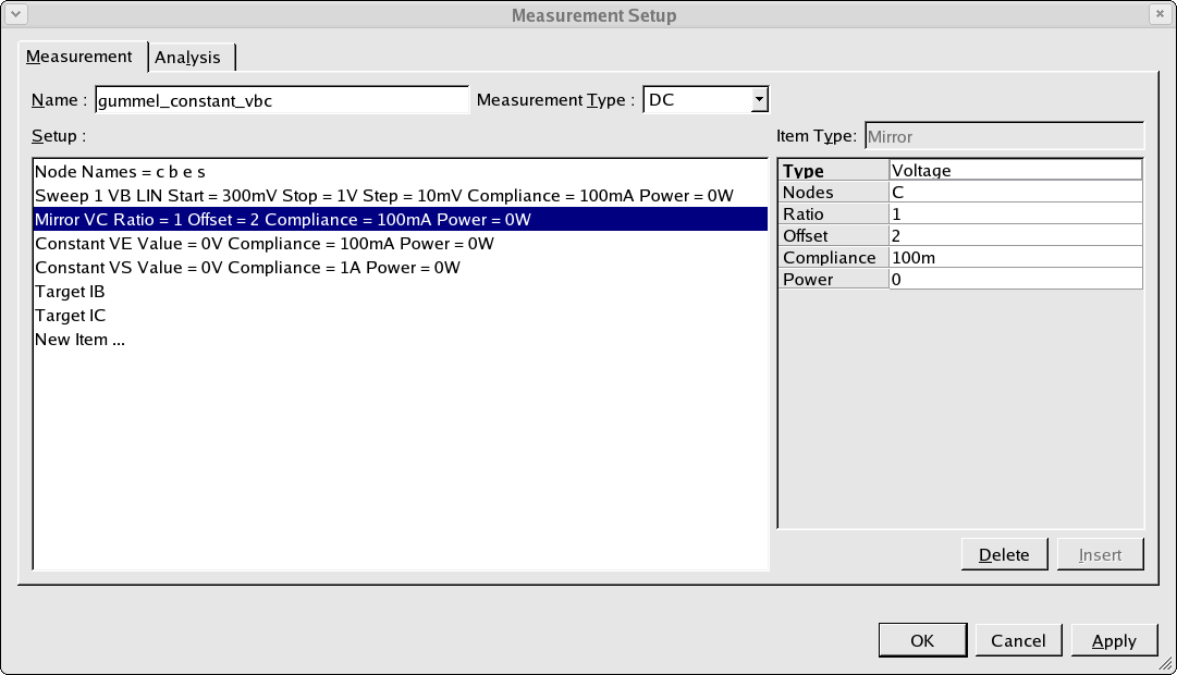
The second method is known as the constant Vbc method. In this measurement we would like to keep
a constant voltage difference between the base and the collector, however, we are changing the
base voltage using a sweep during this measurement. In this case we will use the Mirror in the
measurement setup to ‘follow’ the base voltage sweep. The Mirror is defined as shown in
acq_ex06_05.png
. Here, we define the ratio and the offset of this Mirror value when compared to the primary sweep
value. In order to define a constant voltage difference between the base (which is the
primary sweep) and the collector (which is the Mirror) the ratio should be set to 1 and the
offset should be set to the constant voltage difference value which is required. In this example,
the voltage offset is set to 2 volts reverse bias for the base-collector of this NPN transistor.
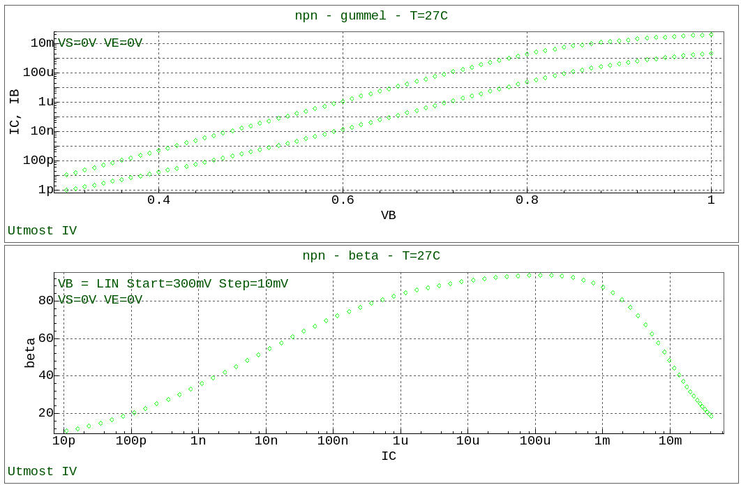
When the measurement is performed, as the base voltage changes, the collector voltage will also
be changed to maintain this constant voltage difference. After the measurement is completed, the
result will be displayed in the viewer as shown in
acq_ex06_06.png
.
Graphics