Requires: Utmost IV, SmartSpice, SmartView
Minimum Versions: Utmost IV 1.11.0.R, SmartSpice 4.10.6.R, SmartView 2.28.2.R
This example describes how to perform bipolar capacitance measurements.
The project file
acq_ex12.prj
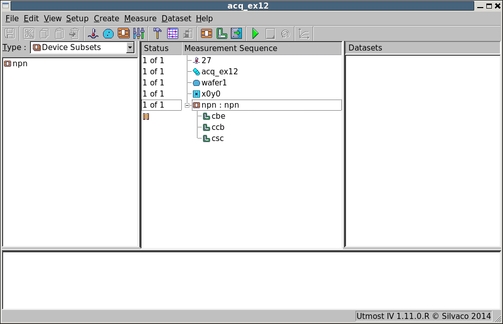
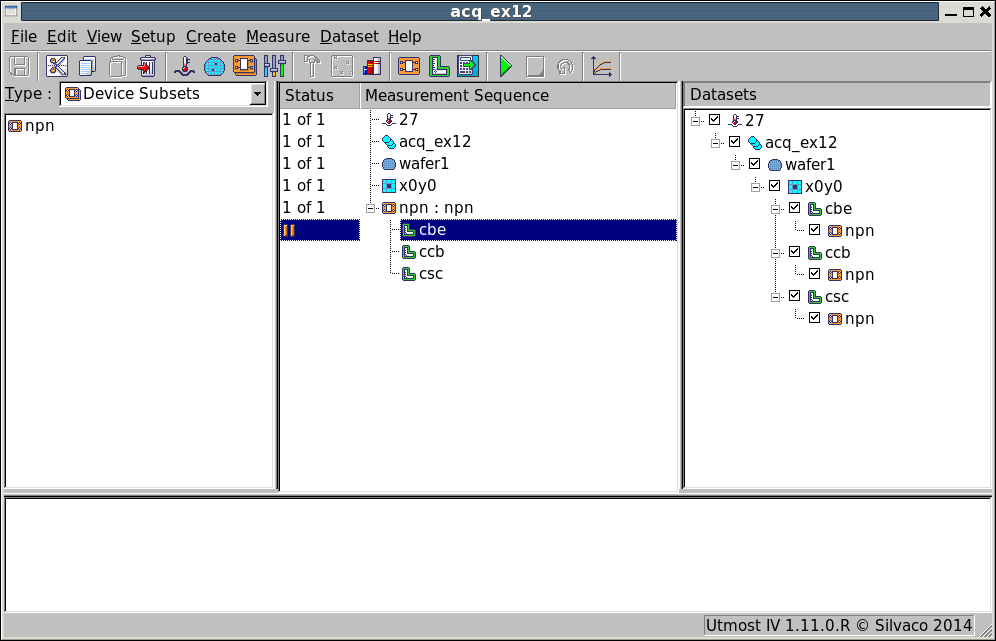
for this example should be loaded into your database. When opened, the
project will look as shown in
acq_ex12_01.png
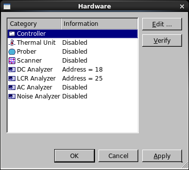
. In the project hardware, the DC Analyzer and LCR Analyzer are enabled for measurement as
shown in
acq_ex12_02.png
.
This project includes three capacitance measurement setups for the various junctions in the
four terminal vertical bipolar device and are defined as
- cbe Base-Emitter junction capacitance
- ccb Collector-Base junction capacitance
- csc Substrate-Collector junction capacitance
There are two important connections when measuring capacitance, the high terminal
(Hi) where the ac bias is applied and the low terminal (Lo) where the measurement of the
ac impedance and thus the capacitance happens. When measuring capacitance it is
important to connect the device correctly.
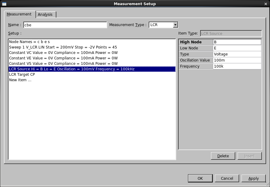
To measure the Base-Emitter capacitance (cbe), the low terminal of the measurement
is connected to the emitter node and the high to the base node of the bipolar as shown in
acq_ex12_03.png
. It is important that the applied bias to the high terminal reverse biases the junction
in order to measure the reverse bias diode capacitance characteristic. The zero volts on the
low terminal can be supplied by the LCR instrument itself. In this case, we set the connection
for this terminal to ‘manual ground’ to indicate that the bias is already taken care of. In
general, when performing capacitance measurements, it is important that the other terminals
are connected to a DC source. You should not allow the other terminals to ‘float’ as the
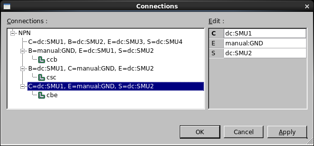
measured capacitance contributions may be affected. The connections for the various measurements
are shown in
acq_ex12_04.png
.
Before measuring any capacitance, you should calibrate or zero the LCR instrument to remove
the effect of the test instrument and test setup from the measured result. If you have a dedicated
open calibration structure, this should be used when calibrating the LCR instrument.
To calibrate the LCR instrument, select the capacitance measurement setup in the measurement
sequence and then select
Measure->Calibrate
from the project menu.
Once calibration is done, capacitance measurement will be performed by selecting
Measure->Run
from the project menu.
For this example, we can now switch the project into its simulation mode by selecting
Measure->Simulation
from the project menu. This will allow us to view the typical characteristics which will
be generated when the measurement is performed.
When the measurement sequence is run, the measured data will be automatically stored in
the database and the measured results will be shown in the dataset selector area of the
acquisition project as shown in
acq_ex12_05.png
.
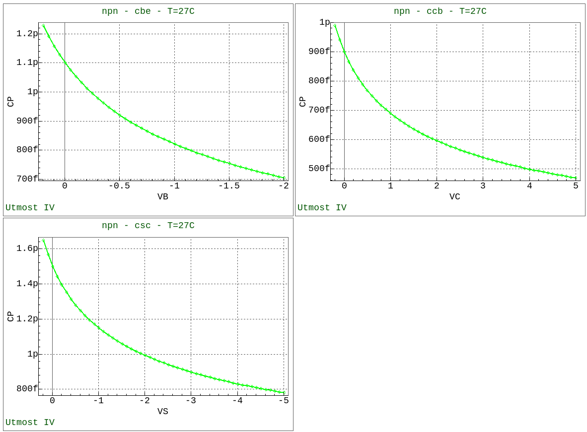
Select all of the data which has been measured and display in the viewer by selecting
Dataset->Plot
from the project menu. This will display all three measured characteristics as shown in
acq_ex12_06.png
.
Graphics