Requires: Utmost IV, SmartSpice, SmartView
Minimum Versions: Utmost IV 1.11.0.R, SmartSpice 4.10.6.R, SmartView 2.28.2.R
This example describes how to perform AC calibration and de-embedding.
The project file
acq_ex13.prj
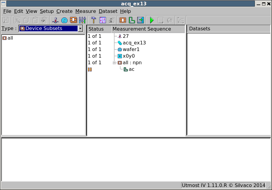
for this example should be loaded into your database. When opened, the
project will look as shown in
acq_ex13_01.png
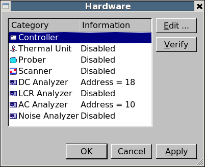
. In the project hardware, the DC Analyzer and AC Analyzer are enabled for measurement as
shown in
acq_ex13_02.png
.
When measuring any AC or RF characteristics, you should calibrate or zero the network
analyzer to remove the effect of the test instrument, cables, probes, etc. from the
measured result.
To calibrate the AC instrument, select the ac measurement setup in the measurement sequence
and then select
Measure->Calibrate
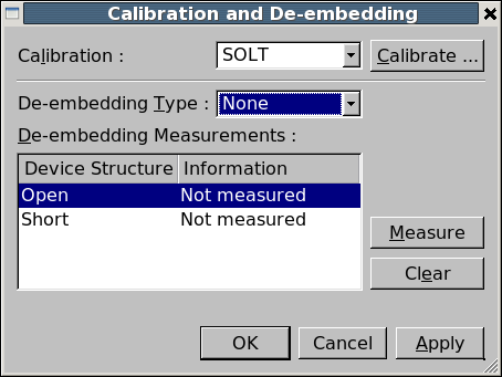
from the menu. This will open the calibration and de-embedding dialog as shown in
acq_ex13_03.png
.
For AC measurements, we will perform an
SOLT
(Short, Open, Load, Through) calibration on the network analyer. Selecting the
SOLT
calibration type and clicking on the
Calibrate
button will open up the calibration dialog. This dialog has five pages;
- The port setup page
- The reflection calibration page
- The isolation calibration page
- The transmission calibration page
- The final confirmation page
It is important that you step through all of these pages and do not cancel
at any time, otherwise the calibration will not be performed correctly.
Port Setup
In the first port setup page of the SOLT calibration dialog, you should select
which DC SMU is connected to each of the two RF ports on the network analyzer.
This will allow Utmost IV to test the resistance of each of the calibration
standards during the calibration procedure. If you choose not to select the DC
bias source here, then no verification of standard resistance will be performed.
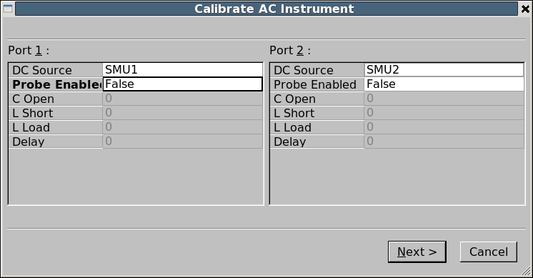
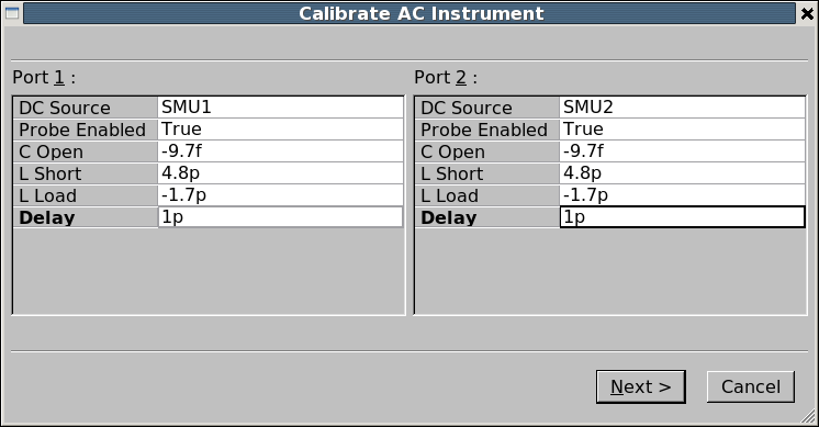
Typically the DC SMU1 source is connected to port 1 bias and DC SMU2 is connected
to port 2 bias as shown in
acq_ex13_04.png
. Also in this first port setup page, you can enter the calibration offsets for
your specific RF probes. This will correct the calibration for the specific
characteristics of the RF probes and calibration substrate which are being used
for the measurement as shown in
acq_ex13_05.png
. After you have finished setting up the ports, select
Next
to move to the next page.
Reflection Calibration
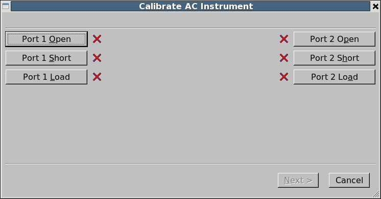
When you first open the reflection calibration page, it will show that none
of the standards have been measured as shown in
acq_ex13_06.png
. Before you can move to the next page of the calibration, all of the
standards must be measured on both of the RF ports.
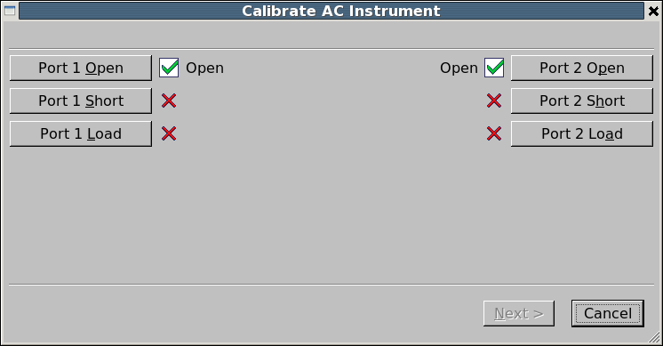
First, the open standard should be connected to each of the two ports in
turn and the
Port 1 Open
or
Port 2 Open
button clicked as appropriate. After the open standard has been measured on
both ports, the dialog should be as shown in
acq_ex13_07.png
. If the DC bias SMU’s were enabled in the port setup page, the resistance
of the standard will be checked and the text
Open
will be shown in the dialog. If instead of this text a low value resistance
is shown, then there may be a problem with the connected calibration standard.
Next, the short standard should be connected to each of the two ports in
turn and the
Port 1 Short
or
Port 2 Short
button clicked as appropriate. After the short standard has been measured on
both ports, the dialog should be as shown in
acq_ex13_08.png
. If the DC bias SMU’s were enabled in the port setup page, the resistance
of the standard will be checked and displayed on the dialog. This resistance
value should be low, on the order of a few ohms, but the exact value will
depend on your equipment setup.
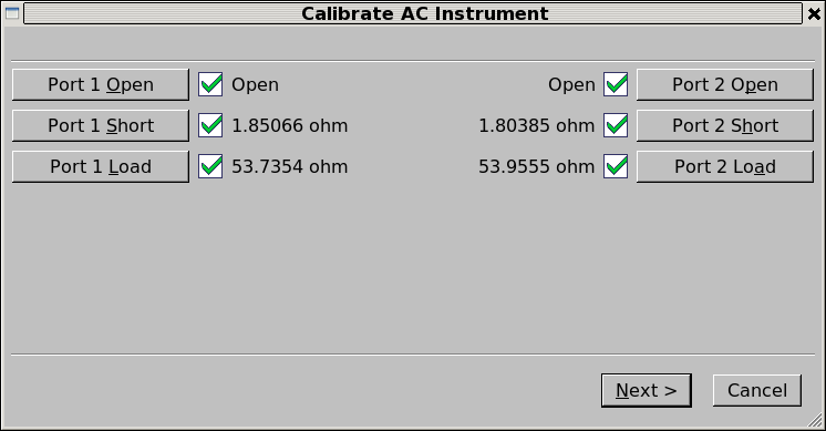
Next, the load standard should be connected to each of the two ports in
turn and the
Port 1 Load
or
Port 2 Load
button clicked as appropriate. After the load standard has been measured on
both ports, the dialog should be as shown in
acq_ex13_09.png
. If the DC bias SMU’s were enabled in the port setup page, the resistance
of the standard will be checked and displayed on the dialog. This resistance
value should be around 50 ohms which is the impedance of the load standard for
the network analyzer, but the exact value will depend on your equipment setup.
If there is a problem during any of the standard measurements, you can click on
the appropriate button again to remeasure. Once all six of the standards are measured,
you can then select
Next
to move to the next page.
Isolation Calibration
For isolation measurement, you should connect a load standard to both of the
RF ports at the same time and then select
Measure Isolation
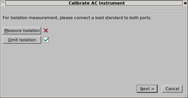
. It is common to omit the isolation calibration step entirely by selecting the
Omit Isolation
. In this example, we will omit the isolation calibration step and afterwards
the dialog will appear as shown in
acq_ex13_10.png
and you can select
Next
to move to the next page.
Transmission Calibration
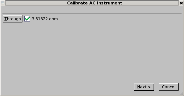
In the transmission calibration, the through standard should be connected between
ports 1 and 2 and the
Through
button clicked. If the DC bias SMU’s were enabled in the port setup page, the resistance
of the standard will be checked and displayed on the dialog as shown in
acq_ex13_11.png
. This resistance value should be a few ohms but the exact value will depend on your equipment
setup. Now you can select
Next
to move to the next page.
Final Confirmation
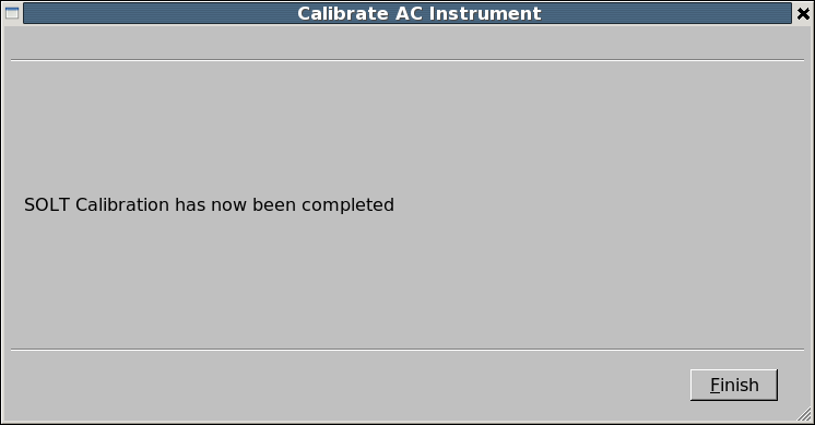
Once the instrument calibration has been finalized the dialog will be as shown in
acq_ex13_12.png
. You should then click on
Finish
to close the SOLT calibration dialog.
Now you have successfully calibrated the network analyzer using your calibration standards
and have defined your reference calibration plane to the tips of your RF probes. The calibration
is typically stored in the AC instrument itself. But there are still more corrections to be made
before measuring your device. Typically, this means performing
Open
and optionally
Short
de-embedding measurements.
De-embedding Measurements
Calibration will zero or remove the effect of the measurement equipment, cables, probes, etc.
The device which is to be measured will also have metal, contacts, vias and pads as part of the
test structure. It is important that these additional parasitics are removed by de-embedding.
The lower section of the calibration dialog deals with the de-embedding measurements as shown in
acq_ex13_03.png
. You must select the type of de-embedding you would like to perform from these four options.
- None
- Open
- Short
- Open and Short
Typically only the open de-embedding is performed and this will correct for parasitic capacitances
which are due to the test structure being measured. This will require a special test structure
to be available which contains all of the metal, vias, pads, etc, but which does not contain the
actual device to be measured.
Optionally, a short de-embedding can also be performed which will correct for parasitic resistances
which are due to the test structure being measured. For well designed test structures, these resistances
are often small and can be ignored. This optional short de-embedding measurement will require a special
short de-embedding structure to available which shorts the signal and ground of each port together,
but which does not contain the device to be measured.
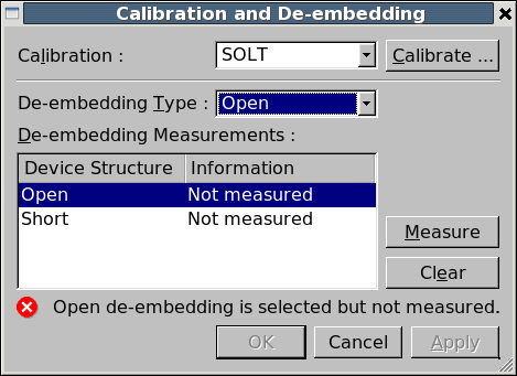
When you select the
Open
de-embedding type, the dialog will remind you to measure the open structure as shown in
acq_ex13_13.png
. The special open de-embedding structure should be connected and then you select the
open device structure from the dialog and click on the
Measure
button. This will then perform the open de-embedding measurement and store the results
in memory.
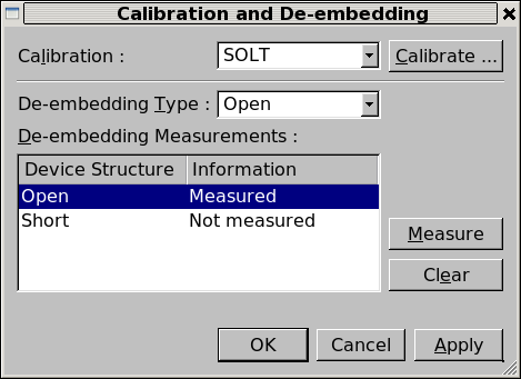
Now both the calibration and the de-embedding have been completed as shown in
acq_ex13_14.png
and you should press the
OK
button to close the calibration dialog. At any time, the calibration dialog can be
re-opened to update the de-embedding measurements.
The AC instrument has now been calibrated and the de-embedding measurements on
the special test structures have been made. You should now connect the device
you want to measure, then select
Measure->Run
from the project menu to perform the measurement. When the data is stored to the
database, the de-embedding data will automatically be used to correct the measured
s-parameter data from your device.
Note that there is only one set of de-embedding data. If you have separate open
structures for each of your devices, you should remeasure the de-embedding
structures before measuring each device.
Graphics