

Requires: SmartSpice & Smartview
Minimum Versions: SMARTSPICE 3.16.12.R
- .Modif parameter variation
The .MODIF can be used to change a parameter value and hence run a number of simulation changes to see the circuit response.
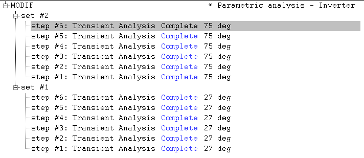
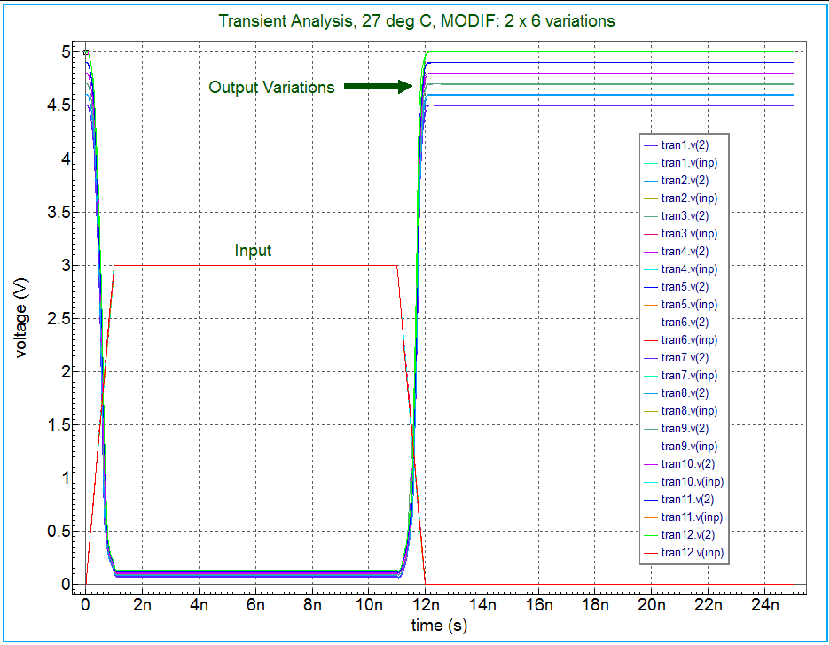
In this simple descrete device inverter circuit we use a couple of MODIF loops to show how this commnad can be cascaded (2 levels here)
to perform 2 steps of 6 itterations each to give 12 transient simulation runs.
The key statement in the input deck is:
.MODIF proff prtbl m2(w)=32.6u LOOP=6 vccDC+=(4.5)0.1v
+MODIF proff prtbl TEMP=75 LOOP=6 vccDC+=(4.5)0.1v
This statement can be used in many ways. For more information see chapter 3 of SmartSpice Users manual.
Graphics
Input Files
mod1.in
* Parametric analysis - Inverter
**********************************
vcc vss 0  DC vccDC
vin inp 0  PULSE(0 3 0 trtf trtf  10ns 40ns)
m1 2  inp  vss  vss  pm  w=wp   l=1.6u
m2 2  inp  0    0    nm  w=30u  l=2.0u
cout  2  0  50ff
.MODEL  pm  PMOS ( level=3 tox=.02e-6
+ phi=0.576 gamma=0 vto=0 alpha=0 kappa=0)
.model  nm  NMOS ( level=3 tox=.02e-6
+ phi=0.576 gamma=0 vto=0 alpha=0 kappa=0)
***** Analysis statement
.TRAN 0.1ns 25ns
***** Measure statements
.MEASURE TRAN delrise DELAY v(inp) RISE=1 VAL=1.5
+      TARG=v(2) FALL=1 VAL='0.5*vccDC'
.MEASURE TRAN maxv2 MAX  v(2)
.MEASURE TRAN delfall DELAY v(inp) FALL=1 VAL=1.5
+      TARG=v(2) RISE=1 VAL='0.5*maxv2'
***** Parameter labels
.PARAM vccDC= 5V wp=4.9u  trtf=1ns
***** Parametric analysis  specification
.MODIF proff  prtbl m2(w)=32.6u  LOOP=6 vccDC+=(4.5)0.1v
+MODIF proff  prtbl     TEMP=75  LOOP=6 vccDC+=(4.5)0.1v
.options nomod
.END
025_modif_sim
[an error occurred while processing this directive]