

Requires: SmartSpice & Smartview
Minimum Versions: SMARTSPICE 4.18.16.R
The benefits of this example are that the user can perform further analysis on saved results without having to re-execute a lengthy simulation. The
example demonstrates this by performing Timing Jitter analysis on a previously executed simulation run.
Referring to the
schematic,
a transient analysis is performed by sourcing and running a simulation on the main “ex1_long.in”
inputdeck. The voltage waveforms at node 3 and 4 are saved in the “ex1_long.raw” simulation results file captured during
the transient analysis.
Separately, the “Clock_jitter_meas.in”
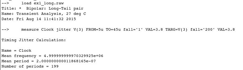
controldeck is sourced. The control section loads the “ex1_long.raw” simulation results file and performs a Timing Jitter
calculation
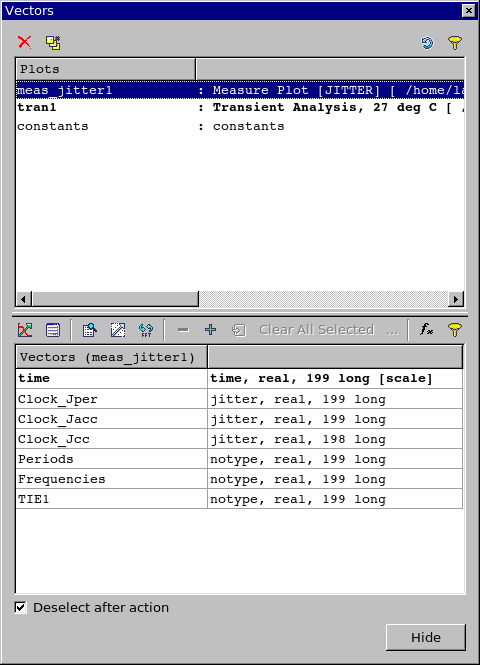
on the voltage information collected at node 3 during the previous simulation run. Furthermore, all Timing Jitter analysis jitter
vectors
are also generated (the .MEASURE … JITTER statement).
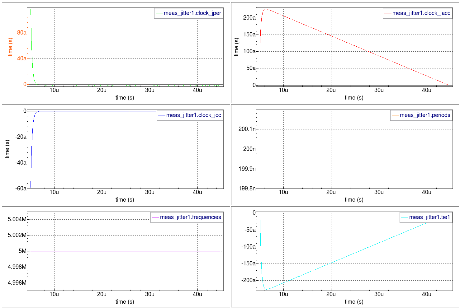
The
waveforms
show all Timing Jitter analysis metrics versus time at node 3.
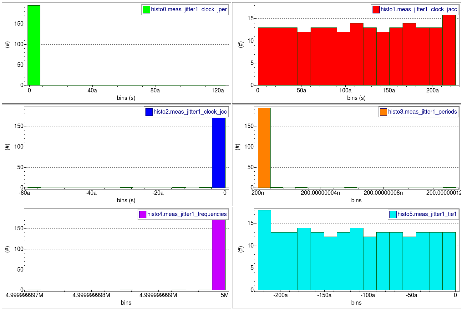
The
histograms
show all Timing Jitter analysis distributions at node 3.
Graphics

Input Files
ex1_long.in
*  Bipolar: Long-Tail pair
***********************************

VIN  1 0  DC 0  SIN(0 0.1 5MEG)  AC 1
VCC  8 0  DC 10
VEE  9 0  DC -12
RS1  1 2  1K
RS2  5 0  1K
RC1  3 8  10K
RC2  4 8  10K
RBIAS  7 8  20K
CLOAD  3 4  5PF
Q1  3 2 6  QNL
Q2  4 5 6  QNL
Q3  6 7 9  QNL
Q4  7 7 9  QNL

.MODEL QNL NPN(BF=80 RB=100 CCS=2PF TF=0.3NS TR=6NS CJE=3PF CJC=2PF VA=50)
*
**.OPTION MEASRAW=0 post keepopinfo
**.OP current 20ns
.TRAN 5NS 50000NS
.save v(3) v(4)
*
.OPTIONS ACCT=2 RELTOL=0.001 NOMOD  post rawpts=300
.END
Clock_Jitter_meas.in
* Timing Jitter measurement
*

.control
    load ex1_long.raw
    measure Clock jitter V(3) FROM=5u TO=45u fall='1' VAL=3.8 TARG=V(3) fall='200' VAL=3.8

.endc

.end
019_jitter_sim
[an error occurred while processing this directive]