

Requires: SmartSpice & Smartview
Minimum Versions: SmartSpice 4.30.5.R + SmartView 2.34.3.R
In a flat Panel display there maybe many lines to drive depending on panel size. You can setup a pulsed source for every line but this is very tedious and prone to mistakes. A better approach is to programatically through Verilog-A setup these Pulses as shown in this simple small example that can be expanded to the larger cases.
The data pulses and scan pulses can be setup through simple Verilog-A files that are then used in conjunction with pulse sources to drive the circuit.
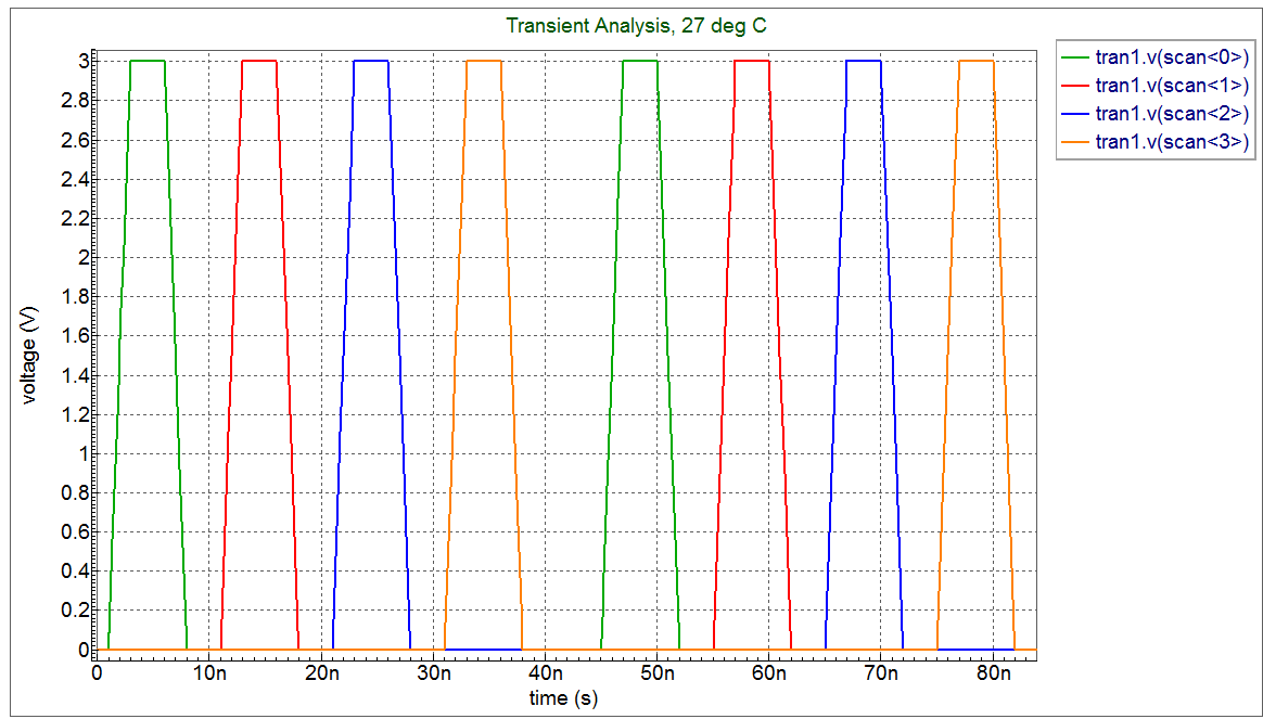
This scan plot
shows the set of scan pulses generated in this example. You can go on and plot all the generated stimulus waveforms to get this
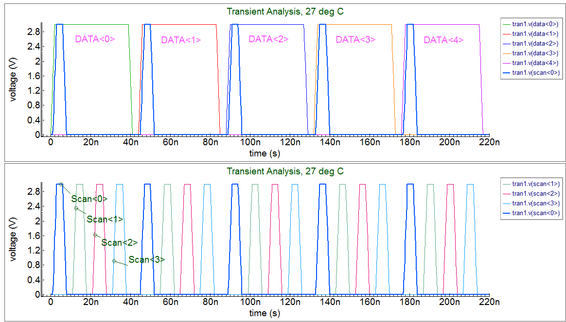
final result of getting all the timing right for a simple 4×5 display case. The driver circuit has to switch cells via long connection lines with parasitic elements that degrade and strech the waveform in time. Here is an example taking a simple pixel design. And using it in a small array(7×13) including parasitic elements. The user can then vary the components and loading to see how the driver timing changes. This can be used as a template for exploring different size arrays and different pixel arrangements.
The input deck is a SPICE file generated from the Gateway schematic shown here
.
Graphics
Input Files
DataGen5.va
`include "discipline.h"

module DatadelayGenerator5(pwlIn,pwlDelayOut);
// Parameters
parameter integer size  = 5;     // Sets the number of inputs to the circuit under test
parameter real tstep    = 44e-9;  // Sets the delay between each input in seconds

input                  pwlIn;
output     [0:size-1]  pwlDelayOut;

electrical             pwlIn;
electrical  [0:size-1] pwlDelayOut;

analog begin
generate i (0,size-1,1) begin
 V(pwlDelayOut[i]) <+ absdelay(V(pwlIn), tstep*i);
// $display("Vpwnin %e, tsp %e  vout %e\n",V(pwlIn),tstep*i,V(pwlDelayOut[i]) );
end
end

endmodule
ScanGen4.va
`include "discipline.h"
//`include "constants.h"

module ScandelayGenerator4(pwlIn,pwlDelayOut);
// Parameters
parameter integer size  = 4;     // Sets the number of inputs to the circuit under test
parameter real tstep    = 10e-9;  // Sets the delay between each input in seconds

input                  pwlIn;
output     [0:size-1]  pwlDelayOut;

electrical             pwlIn;
electrical  [0:size-1] pwlDelayOut;

analog begin
generate i (0,size-1,1) begin
 V(pwlDelayOut[i]) <+ absdelay(V(pwlIn), tstep*i);
end
end

endmodule
tft_small_deck.in
* E:/Silvaco/TFT_example/tft_small_4/5x4
**
* Gateway 2.4.10.R Spice Netlist Generator
**
* Simulation timestamp: 21-Nov-2006 15:15:41.00
**
.param edger = 2n
.param edgef = 2n
.param vpulseh = 3
*
* Schematic name: 5x4
*
Vdata NET2 GND PULSE(0 vpulseh 0  edger edgef 37n 260n)
Vscan NET1 GND PULSE(0 vpulseh 1n edger edgef 5n 52n)
X1 DATA<0> SCAN<0> tft
X2 DATA<1> SCAN<0> tft
X3 DATA<2> SCAN<0> tft
X4 DATA<3> SCAN<0> tft
X5 DATA<4> SCAN<0> tft
X6 DATA<0> SCAN<1> tft
X7 DATA<1> SCAN<1> tft
X8 DATA<2> SCAN<1> tft
X9 DATA<3> SCAN<1> tft
X10 DATA<4> SCAN<1> tft
X11 DATA<0> SCAN<2> tft
X12 DATA<1> SCAN<2> tft
X13 DATA<2> SCAN<2> tft
X14 DATA<3> SCAN<2> tft
X15 DATA<4> SCAN<2> tft
X16 DATA<0> SCAN<3> tft
X17 DATA<1> SCAN<3> tft
X18 DATA<2> SCAN<3> tft
X19 DATA<3> SCAN<3> tft
X20 DATA<4> SCAN<3> tft

YVLG_vsource net2  DATA<0:4> DatadelayGenerator5
YVLG_vsource1 net1 SCAN<0:3> ScandelayGenerator4
*
* Schematic name: tft
*
.SUBCKT tft X_L Y_T
*
C1 NET1 GND 20e-6
M1 Y_T NET2 NET1 GND NM L=0.4U W=5U
R1 NET2 X_L 1
R2 NET1 GND 1000k
*
.ENDS tft
*
* Global Nodes Declarations
*
* .GLOBAL VDD GND

*
* End of the netlist

*
* Markers to save
*
*.SAVE V(DATA<4>) V(SCAN<0>)
.save V(DATA<*>) V(SCAN<*>)

* TFT simple array example - 5 x 4
****************************************
.OPTION RAWPTS=500 POST
.verilog  DataGenNew5.va
.verilog  ScanGenNew4.va
.model nm nmos level=49
.model DatadelayGeneratorVerilog VLG MODULE = DatadelayGenerator5
.model ScandelayGeneratorVerilog VLG MODULE = ScandelayGenerator4
.options acct=2
*.tran 5n 500n
.tran 5n 250n
.END