

Requires: SmartSpice & Smartview
Minimum Versions: SMARTSPICE 4.6.5.R
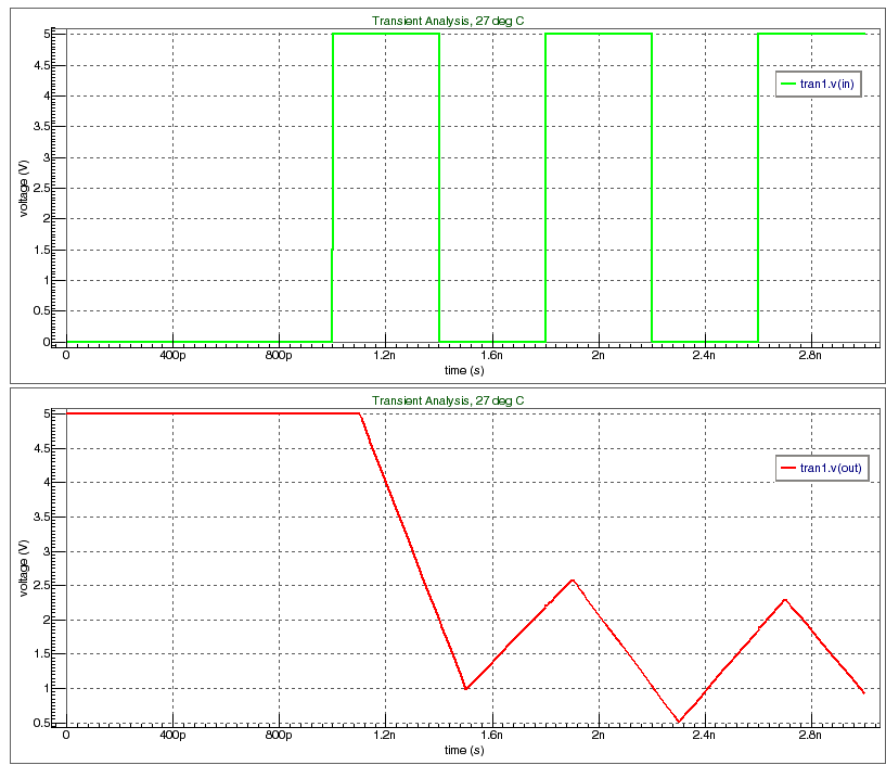
The 2 bit MOSFET adder input deck with .TRAN and .MEASURE analysis shows by rubberbanding the voltage source pulse parameters the sensitivity to input stimulus of simple circuit.
Graphics
Input Files
inverter.va
`include "discipline.h"


module inverter (in,out);

   input             in;
   output 	    out;
   voltage in,out;

   parameter  real  vout_high = 5,
                    vout_low  = 0,
                    vth       = vout_high/2,
                    tdelay    = 0.1n from [0:inf),
                    trise     = 1.0n from [0:inf),
                    tfall     = 0.5n from [0:inf);

   real 	    vout;

   analog
     begin

	@(initial_step)
	     begin
		$strobe("tdelay = %g trise = %g tfall = %g", tdelay, trise, tfall );
	     end

             @(initial_step or cross(V(in) - vth))
	     begin
		if (V(in) > vth) vout = vout_low;
		else             vout = vout_high;
	     end

	V(out) <+ transition(vout,tdelay,trise,tfall);
     end
endmodule
rubberband_example_14.in
* Simple inverter cir using VA.
* Rubberband parameters:
* .PARAM  PWIDTH

*************************************************************

.VERILOG   "inverter.va"

*************************************************************

YVLG_INV  IN   OUT    INVERTER vout_high=5

RL00  OUT    OUTT  10
CL00  OUTT   0     1p


.PARAM  PWIDTH=0.4n  PER='PWIDTH*2    ; abnormal output

 VIN1      IN   0    PULSE (0 5  1n  1p  1p  PWIDTH  PER)   ; RZ pulse

*************************************************************

.TRAN 10p 3n

.measure tran c1 cross v(out) val=2.5
.measure tran c1 cross v(out) val=2.5 occur=3

.save TRAN v(in) v(out)

.END