

Requires: SmartSpice & Smartview
Minimum Versions: SMARTSPICE 4.18.16.R
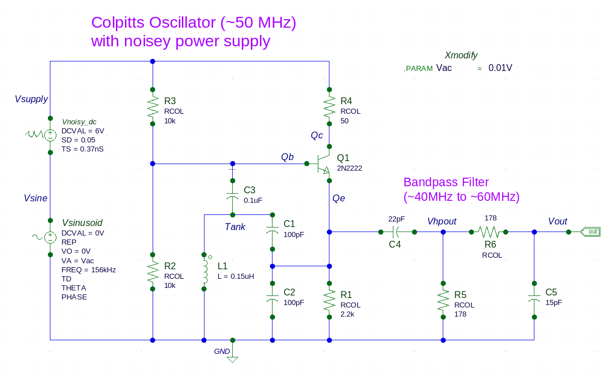
This jitter analysis example demonstrates jitter performance for a discrete Colpitts Oscillator
circuit
due to a noisey power supply.
Important SmartSpice features demonstrated in this example include the following:
- Creating a power supply which includes both random and deterministic noise components.
- Executing a transient analysis and extracting the JITTER metrics using a .MEASURE statement.
- Characterizing the oscillator’s jitter performance by modifying the deterministic noise amplitude through a .MODIF statement.
- Observing the distribution effects on jitter performance as the deterministic noise exceeds the random noise.
- Generating Fast Fourier Transforms (FFTs) to observe spectral distributions in the frequency domain at various points in the circuit.
The
inputdeck shows how a nominal 6 volt DC supply is specified to include a random noise characteristic. Next, a sinusoidal source injects
deterministic noise into the power supply line with an amplitude determined by the Vac parameter. The series combination of these
two sources create the power supply line voltage for the oscillator circuit.
To see how the rest of the oscillator circuit responds to the presence of this power supply noise, a Timing Jitter analysis
is performed for all supported metrics over at least 10,000 cycles (the .TRAN statement). Notice that the jitter analysis excludes the
oscillator’s initial stabilization time (the FROM and TO attributes of the .MEASURE for JITTER).
To understand the oscillator’s jitter performance due to random and deterministic noise, the sinusoidal source’s voltage
amplitude is modified and then Timing Jitter analysis metrics are collected for each Vac value (the .MODIF statement).
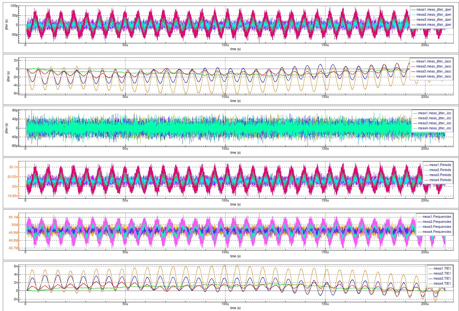
The
waveforms
show all Timing Jitter analysis metrics versus time at each deterministic sinusoidal voltage injected on the power supply line.
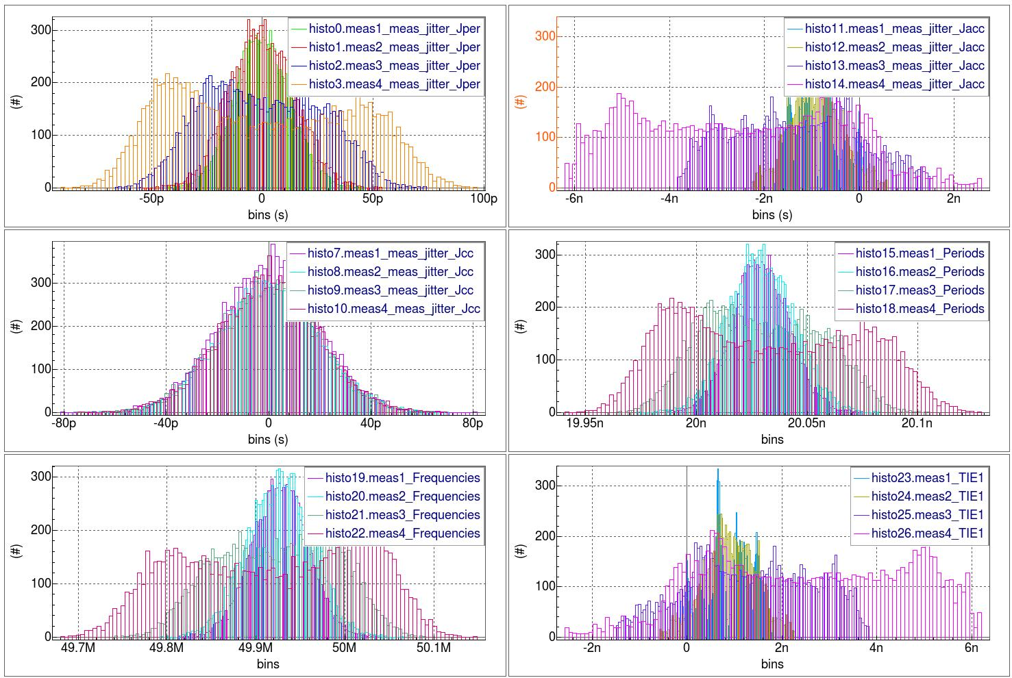
The
histograms
show all Timing Jitter analysis distributions at each deterministic sinusoidal voltage injected on the power supply line.
Notice how the period histogram morphs from a bell curve to a bathtub-shaped distribution. As expected, the cycle-to-cycle
jitter remains unaffected as the deterministic noise increases.
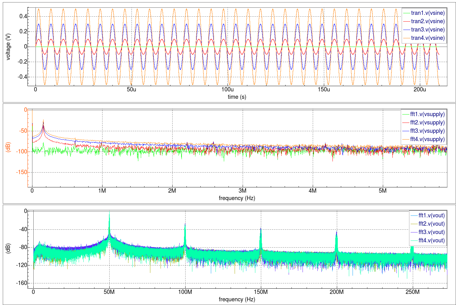
The
spectral plots
illustrate the normalized spectral frequency content at each deterministic sinusoidal voltage injected on the power supply line.
Notice how the FFT vector information sent to the SmartSpice output window can be suppressed (the set suppressfftoutput = true statement).
Graphics
Input Files
Colpitts_Osc.in
********************************************************************
*  http://how-to.wikia.com/wiki/How_to_build_an_oscillator_circuit
*  http://www.electronics-tutorials.ws/filter/filter_4.html
********************************************************************

* Schematic name: Colpitts_Osc

* Gateway 3.4.1.R Spice Netlist Generator
* Simulation timestamp: 13-Aug-2015 15:59:40
* Workspace name:       ./Colpitts.workspace
* Simulation name:      ./Colpitts_Osc.schlr

*
*
**** NETLIST *****

.PARAM Vac=0.01V

Vnoisy_dc Vsupply Vsine DC 6V SD=0.05 TS=0.37nS
Vsinusoid Vsine GND DC 0V SIN(0V Vac 156kHz )

* The bandpass output filter
R6 Vhpout Vout RCOL 178
R5 Vhpout GND RCOL 178
C4 Qe Vhpout 22pF
C5 Vout GND 15pF

* The discrete oscillator circuit
L1 Tank GND 0.15uH
C3 Qb Tank 0.1uF
C2 Qe GND 100pF
C1 Tank Qe 100pF
R4 Vsupply Qc RCOL 50
R3 Vsupply Qb RCOL 10k
R2 Qb GND RCOL 10k
R1 Qe GND RCOL 2.2k
Q1 Qc Qb Qe 2N2222

* Global Nodes Declarations
.GLOBAL GND

**** End of the netlist *****

*
* Markers to save
*
.SAVE V(Qb) V(Qc) V(Qe) V(Tank) V(Vhpout) V(Vout) V(Vsine) V(Vsupply)

*
*
**** ANALYSIS *****
.options nomod nodeck post

.param SIMEND = 210000nS
.param JSTART = 450nS
.param JSTOP = SIMEND

.tran 0.001n SIMEND 0n 0.1n

.measure meas_jitter JITTER V(Vout) RISE From=JSTART To=JSTOP jtype=all

.fft V(Vsupply) V(Vsine) V(Qe) V(Vhpout) V(Vout) NP=524288 START=JSTART FORMAT=norm

.MODIF PRTBL LOOP=4 Vac=LIST(0.001V 0.1V 0.3 0.5V)

*
*
**** CONTROL *****
.control
    set suppressfftoutput=true
.endc

*
*
************* COLPITTS OSCILLATOR SIM - MODEL CARDS ***********

.MODEL RCOL R (
+tnom     = 27             rsh      = 85.752         dw       = 1.53101e-07
+dlr      = 1.31e-07       tc1      = 0.000916201    tc2      = 7.70194e-06
+noise    = 3.8 )

*** Plastic
.MODEL 2N2222 NPN (
+LEVEL    = 1              IS       = 2.14357e-14    BF       = 243.213
+NF       = 1              BR       = 12.8915        NR       = 1.01022
+ISE      = 4e-16          NE       = 1.5            ISC      = 1.43496e-11
+NC       = 1.49247        VAF      = 170            VAR      = 24
+IKF      = 0.494878       IKR      = 0.20008        RB       = 0.02
+RBM      = 0.01           IRB      = 0              RE       = 0.608696
+RC       = 0.26087        CJE      = 2.66249e-11    VJE      = 0.764689
+MJE      = 0.358894       FC       = 0.5            CJC      = 1.10726e-11
+VJC      = 0.553608       MJC      = 0.340454       CJS      = 0
+VJS      = 0.8            MJS      = 0.33           TF       = 1e-10
+XTF      = 1              ITF      = 0.01           VTF      = 5
+PTF      = 20             TR       = 1e-08          XTB      = 1.5
+EG       = 1.17           XTI      = 3 )

*** Metal
*.MODEL 2N2222 NPN (
*+LEVEL    = 1              IS       = 4.27057e-14    BF       = 221.77
*+NF       = 1              BR       = 13.5565        NR       = 1.01022
*+ISE      = 3.23279e-16    NE       = 1.14083        ISC      = 2.17391e-11
*+NC       = 1.49247        VAF      = 328.261        VAR      = 24
*+IKF      = 2.08704        IKR      = 0.20008        RB       = 0.02
*+RBM      = 0.01           IRB      = 0              RE       = 0.508696
*+RC       = 0.26087        CJE      = 3.85181e-11    VJE      = 0.73133
*+MJE      = 0.343516       FC       = 0.5            CJC      = 1.00103e-11
*+VJC      = 0.5            MJC      = 0.289732       CJS      = 0
*+VJS      = 0.8            MJS      = 0.33           TF       = 1e-10
*+XTF      = 1              ITF      = 0.01           VTF      = 5
*+PTF      = 20             TR       = 1e-08          XTB      = 1.5
*+EG       = 1.17           XTI      = 3 )


***************************************************************************
*
* The models below are obtained from the following internet link:
*
* http://www.centralsemi.com/docs/CSM/2N2222.LIB
*
***************************************************************************

******
* Spice Model
* Item: 2N2222
* Date: 5/06/2014
* Revision History: A
*==========================================================
* This model was developed by:
* Central Semiconductor Corp.
* 145 Adams Avenue
* Hauppauge, NY 11788
*
* These models are subject to change without notice.
* Users may not directly or indirectly re-sell or
* re-distribute this model. This model may not
* be modified, or altered without the consent of Central Semiconductor Corp.
*
* For more information on this model contact
* Central Semiconductor Corp. at:
* (631) 435-1110 or Engineering@centralsemi.com
* http://www.centralsemi.com
*==========================================================
******
*SRC=2N2222;2N2222;BJTs NPN; Si;  60V  0.800A  250MHz   Central Semi Central Semi

*.MODEL 2N2222  NPN (IS=2.20f NF=1.00 BF=240 VAF=114
*+ IKF=0.293 ISE=2.73p NE=2.00 BR=4.00 NR=1.00
*+ VAR=24.0 IKR=0.600 RE=0.194 RB=0.777 RC=77.7m
*+ XTB=1.5 CJE=24.9p VJE=1.10 MJE=0.500 CJC=12.4p VJC=0.300
*+ MJC=0.300 TF=371p TR=64.0n EG=1.12 )

******

.END
020_jitter_sim_detailed
[an error occurred while processing this directive]