

Minimum Versions: SmartSpice 4.6.5.R
SmartSpice should be run in the interactive GUI mode and the
input deck containing a PWL voltage stimulus sourced.
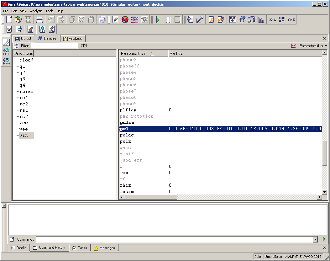
Select through the SmartSpice GUI menu VIEW -> CIRCUIT -> DEVICES. This opens a window to
display
devices on the left pane and attributes of the selected device in the right pane. If you double-click the
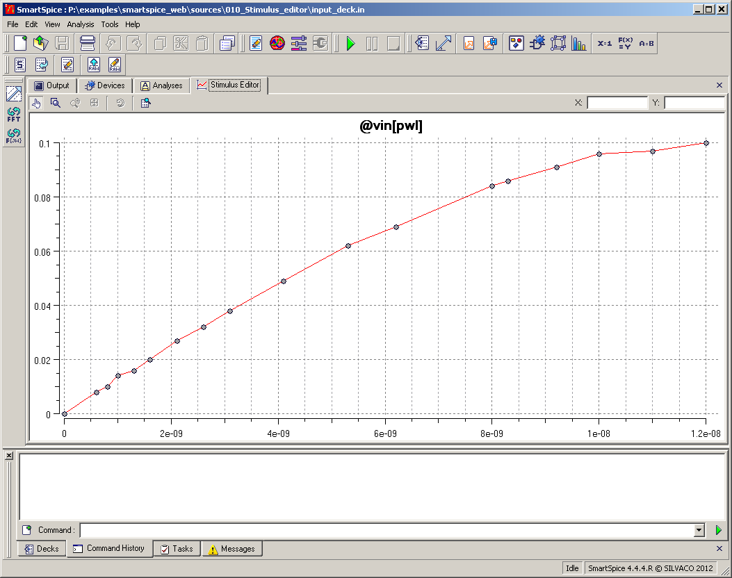
PWL definition shown in bold print you will get a display window showing the PWL
waveform
.
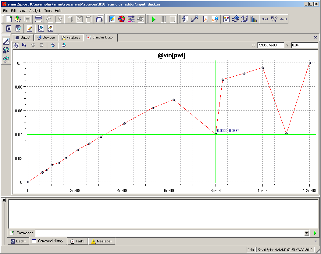
By clicking the left mouse button over the selected point in the waveform you get a marker displaying the data point value as shown in
waveform
where you can see 2 data points have been dragged to a new value.
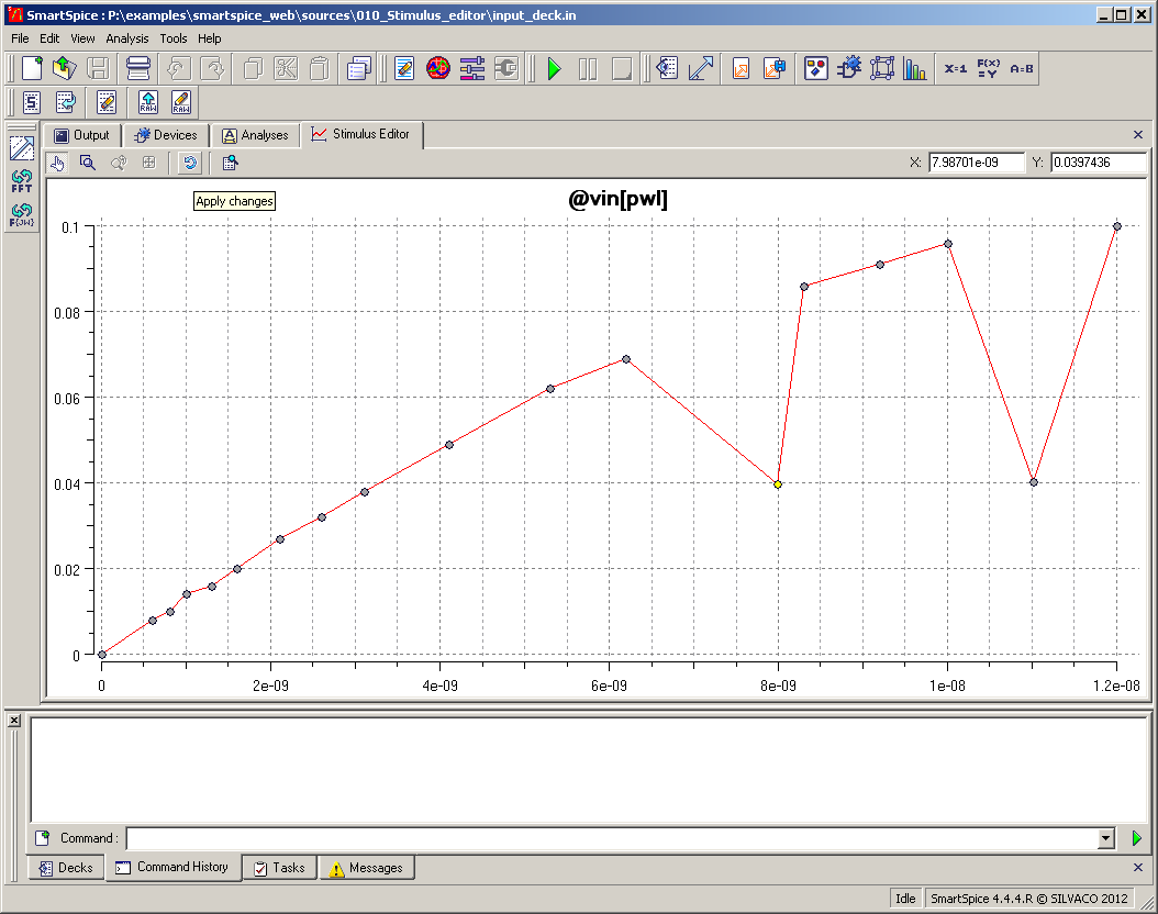
If this modified waveform is the desired stimulus you need to save
this data to the input deck PWL definition by clicking on the 5th icon of the
window
. In this way you can create the desired waveform for the voltage-source to stimulate the circuit.
This functionality checks the waveform used to stimulate the circuit, allowing modifications in shape without the need to do a simulation first.
This could save considerable time if the simulation run was a long one.
(Additional information can be found in the SmartSpice user manual).
Graphics
Input Files
input_deck.in
DEMO EXAMPLE 1: INPUT FILE
*
**VIN  1 0  DC 0  SIN(0 0.1 5MEG)  AC 1
VIN 1 0 DC 0 PWL (0.0 0.0 0.6n 8m 0.8n 10m 1n 14m 1.3n 16m 1.6n 20m 2.1n 27m 2.6n 32m
+ 3.1n 38m 4.1n 49m 5.3n 62m 6.2n 69m 8.n 84m 8.3n 86m 9.2n 91m 10n 96m 11n 97m 12n 0.1)

VCC  8 0  DC 10
VEE  9 0  DC -12
RS1  1 2  1K
RS2  5 0  1K
RC1  3 8  10K
RC2  4 8  10K
RBIAS  7 8  20K
CLOAD  3 4  5PF
Q1  3 2 6  QNL
Q2  4 5 6  QNL
Q3  6 7 9  QNL
Q4  7 7 9  QNL

.MODEL QNL NPN(BF=80 RB=100 CCS=2PF TF=0.3NS TR=6NS CJE=3PF CJC=2PF VA=50)
*
.OPTION MEASRAW=0 post keepopinfo post=2

.OP current 20ns
.TRAN 0.1NS 50NS
*
.save tran V(3)
.OPTIONS ACCT RELTOL=0.001 NOMOD

.END