

Requires: Utmost IV, SmartSpice, SmartView
Minimum Versions: Utmost IV 2.19.2.R, SmartSpice 5.2.0.R, SmartView 2.2207.0.R
This example shows how to use the Utmost IV Corner and Retargeting module to generate typical, slow and fast corner models starting from an existing MOSFET SPICE base (or nominal) model card.
The typical corner data in general comes from the statistical mean values of the targets, based on a large set of measurements. Because of this, the typical target values are usually slightly different from the ones predicted by the base (nominal) model card, which is presumably extracted based on a reference wafer (or “golden” wafer). As a consequence, the typical corner model also needs to be extracted, as well as the other two corner models.
For this example, the “SS” (“slow”) and “FF” (“fast”) values of the TOXE parameter are specified as +8% and -8% of the nominal value for the “FF” and “SS” corners, resepectively.
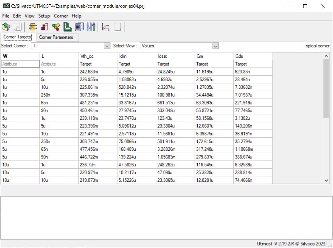
The project file cor_ex04.prj for this example should be loaded into your Utmost IV Corner and Retargeting module. The corner module uses Electrical Table (ET) data. The measured data is already included in the project, as shown in the cor_ex04_01.png
.
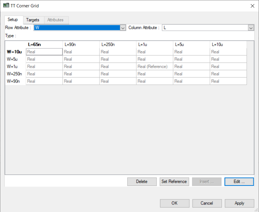
Each row in the table represents a specific device, with a particular set of attribute values. There are 30 rows in total for each corner. One can also examine the available combinations of attribute values by selecting the Corner->Corner Grid menu item, as shown in cor_ex04_02.png
. The grid dialog shows that the “TT” corner data includes 5 W values by 6 L values, for a total of 30 rows.
The columns in the data table can be either attributes (the first 2 columns, in this example) or targets. The data used in this example includes two attributes, W and L, and five targets, Vth_cc, Idlin, Idsat, Gm and Gds.
The targets are specific measurements (extractions) performed on the devices. The target definitions in the project, including their measurement setups, extractions and variables, must be the same as the ones that have been used when acquiring the data in the data table.
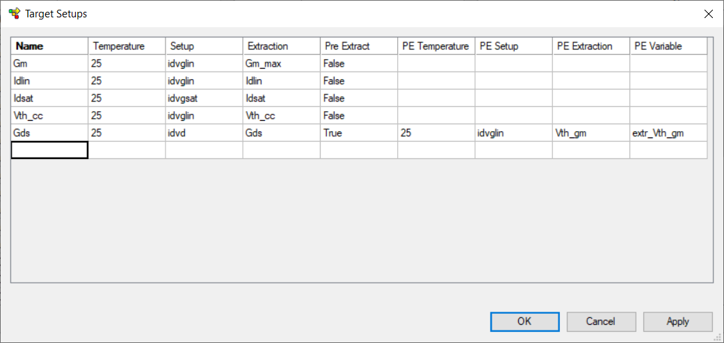
One can examine and edit the target definitions by selecting the Setup->Target Setups menu item, as shown in cor_ex04_03.png
. Each target must have the following components:
- Name: the name of the target
- Temperature: the temperature at which the target is measured
- Setup: the measurement setup used to generating device characteristics at the given temperature
- Extraction: the extraction performed on the device characteristics
- Pre Extract: indicates whether or not a preliminary extraction is needed in order to measure the target.
If a preliminary extraction is not required, the last 4 columns are empty. If a preliminary extraction is needed, the last 4 columns will contain:
- PE Delta Temperature: the temperature difference versus the main extraction, at which the preliminary extraction is performed
- PE Setup: the measurement setup used to generating device characteristics for the preliminary extraction
- PE Extraction: the preliminary extraction
- PE Variable: the variable name to store the result of the preliminary extraction
One can observe that the “Gds” target does require a preliminary extraction, while the other targets do not. In the case of “Gds” a preliminary “Vth_gm” extraction is needed, and its result will be saved in the “extr_Vth_gm” variable. The value of the “extr_Vth_gm” variable will be further used in the calculation of the “Gds” target.
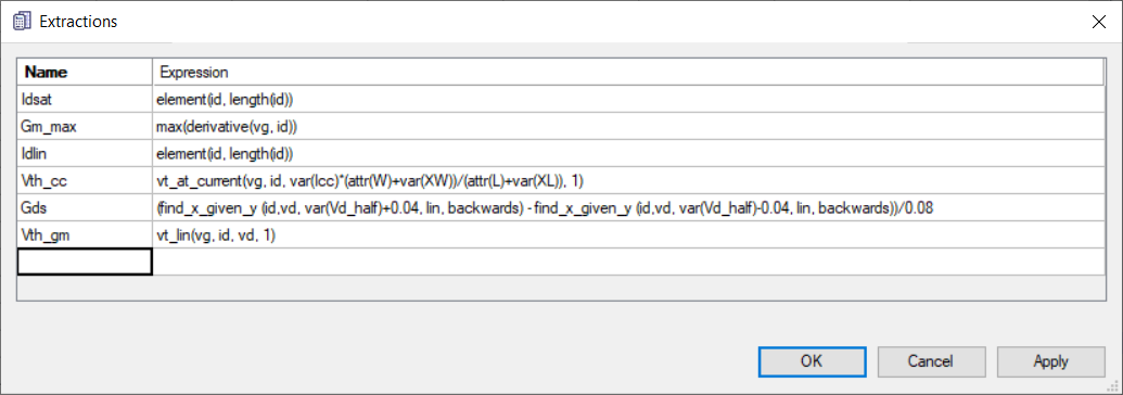
The extraction definitions can be examined by selecting the Setup->Extractions menu item, which opens the “Extractions” Dialog, as shown in cor_ex04_04.png
. The extractions may depend on device attributes and/or on project variables. For example, the Vth_cc extraction is described by an expression that depends on the “L” and “W” attributes and on the “XL” and “XW” variables. The expression of the “Gds” extraction also depends on the “Vd_half” variable.
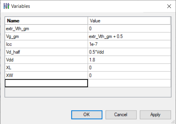
The project variables can be examined by selecting the Setup->Variables menu item, which opens the “Variables” Dialog, as shown in cor_ex04_05.png
. We notice the XL, XW and Vd_half variables, that are used in the extractions. We also notice the “extr_Vth_gm” variable, which is used in the definition of the “Gds” target, and another variable, “Vg_gm”, which depends on it.
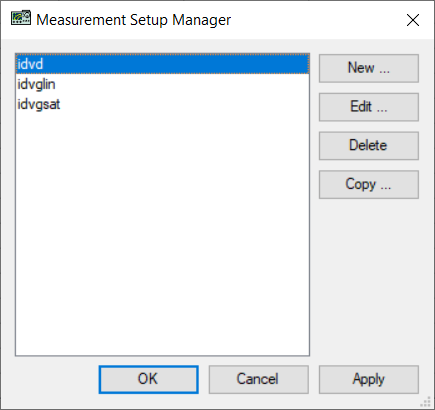
The measurement setups can be examined by selecting the Setup->Measurement Setups menu item, which opens the Measurement Setup Manager, as shown in cor_ex04_06.png
.
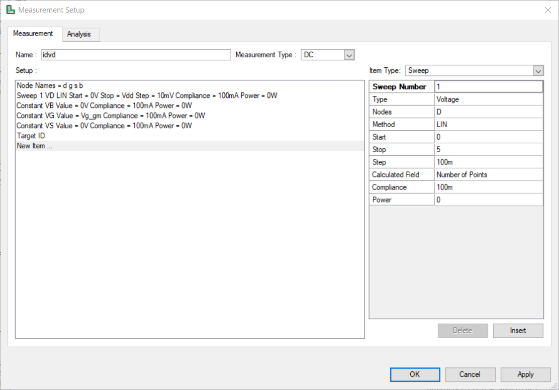
One can select a measurement setup, for example “idvd”, and click the “Edit” button to examine and edit its contents as illustrated in cor_ex04_07.png
. The values used in the measurement setups may depend on project variables. In this example one can notice the usage of the “Vdd” variable in the Vd sweep. We also notice the “Vg_gm” variable that is used to set the constant value of Vg. As the value of the “Vg_gm” variable depends on the “extr_Vg_gm” variable, we can understand the reason that the “Gds” target, which is based on the “idvd” measurement setup, requires a preliminary extraction:
- First, a “Vth_gm” extraction is run based on the “idvglin” measurement setup, and the resulting value is stored in the “extr_Vth_gm” variable.
- Then, the value of the “Vg_gm” variable is calculated based on “extr_Vth_gm” (Vg_gm = extr_Vth_gm + 0.5).
- The Vg_gm value is further used in the “idvd” measurement setup.
- Finally, the “Gds” extraction is performed based on the “idvd” measurement setup.
The data table has four views, which can be selected by using the Select View widget, as follows:
- Values: the data values to match
- Simulations: the simulated values (empty until a simulation is performed)
- Errors: the differences between data and simulated values (empty until a simulation is performed)
- Settings: the type and the values of the two warning levels for each target in the table (the error specifications)
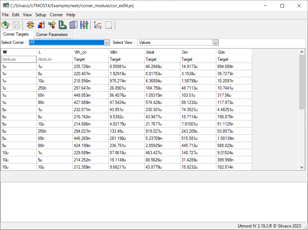
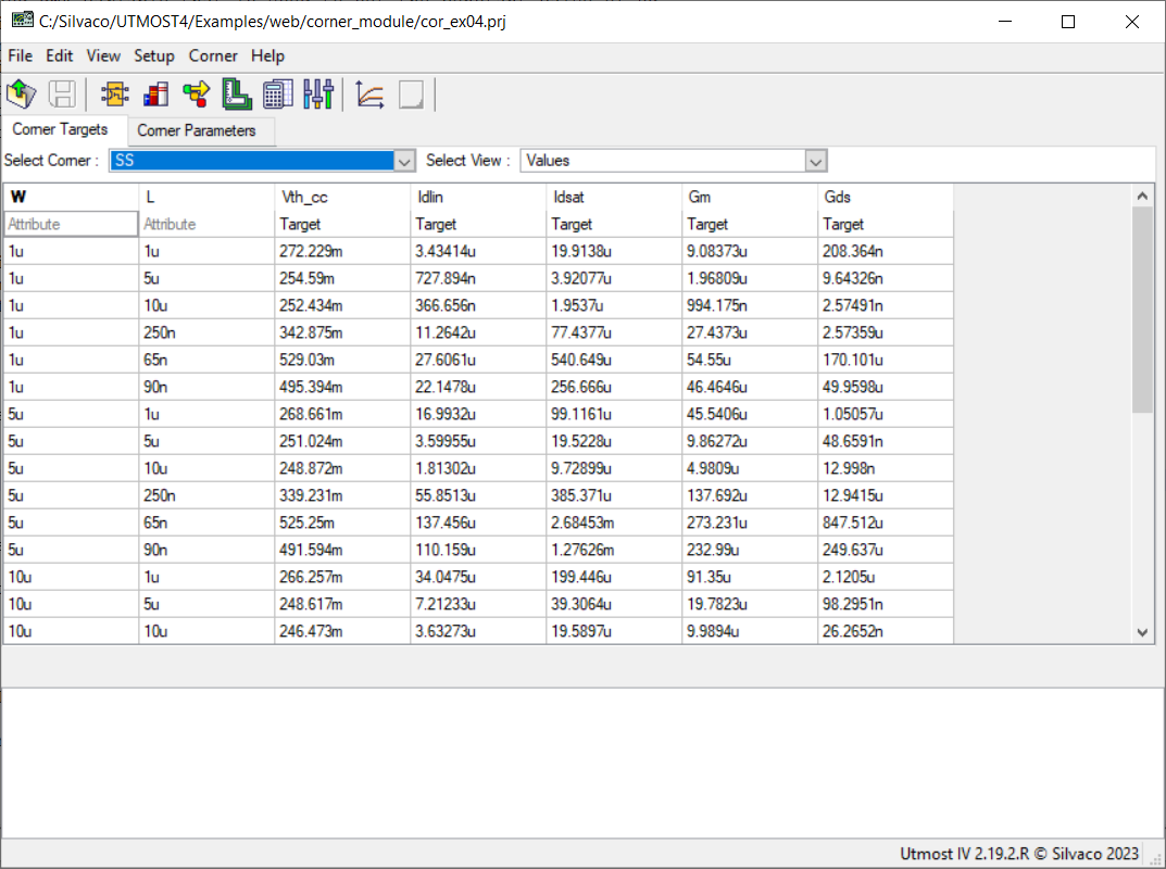
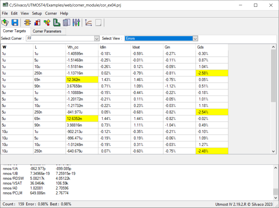
In this example, data tables are available for the typical case, and for two additional corners (“FF” and “SS”, respectivaly). Switching from one corner to another can be done through the Select Corner widget. This will show the data for the “FF” and “SS” corners, as seen in cor_ex04_08.png
and cor_ex04_09.png
, respectively.
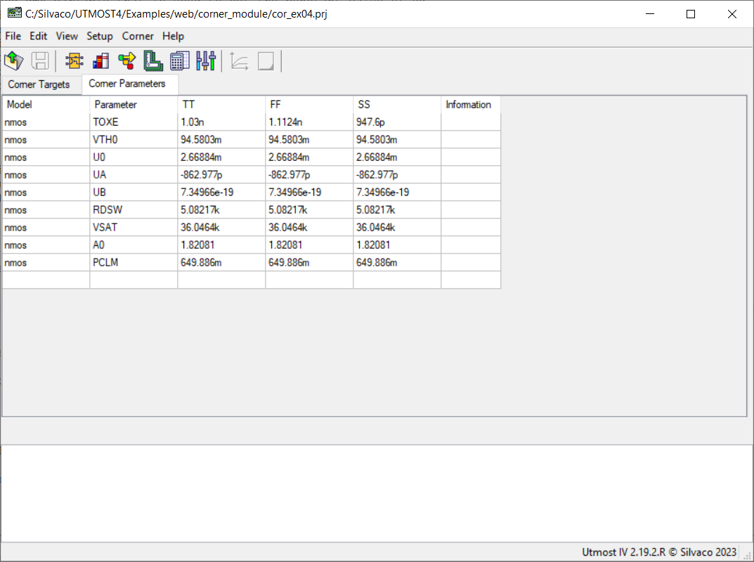
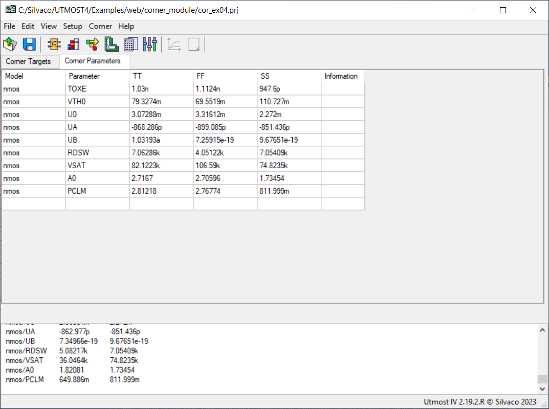
The parameters that are already preselected for this project can be examined by selecting the “Corner Parameters” tab, as shown in cor_ex04_10.png
. The values of the TOXE parameter for each corner are set based on the specifications:
- Nominal TOXE for the Typical corner (1.03nm)
- 108% of the nominal TOXE for the FF corner (1.1124nm)
- 92% of the nominal TOXE for the SS corner (0.9476nm)
The values of all other model parameters are all based on the nominal (base) model card.
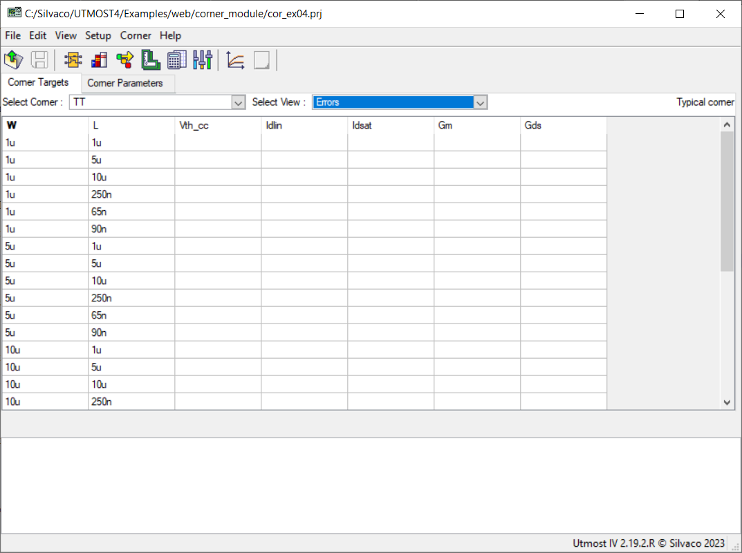
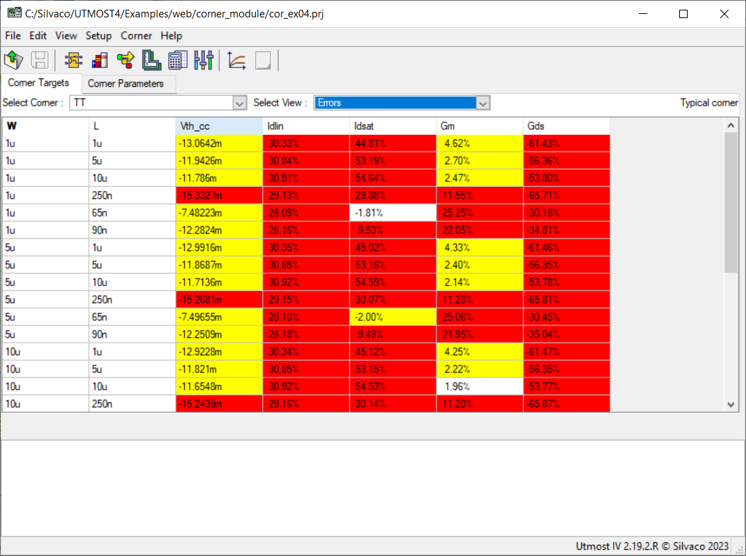
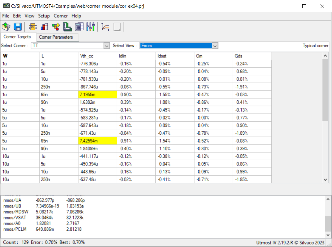
Switching back to the “Corner Targets” tab, we select the “TT” corner from the “Select Corner” drop-down list and the “Errors” from the “Select View” drop-down list, as shown in cor_ex04_11.png
.
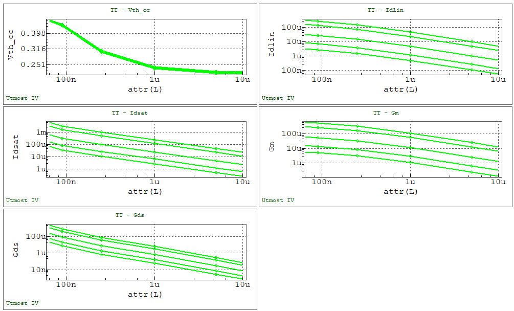
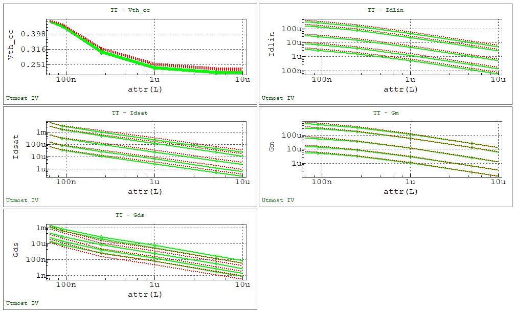
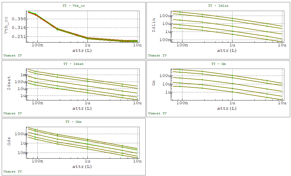
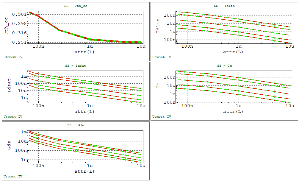
The data and the simulated values can be also examined using trend plots. This is done by selecting the Corner->Plot menu item, which will display the plots in the viewer, as shown in cor_ex04_12.png
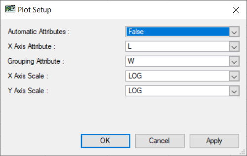
. For this example the plots are shown versus the L attribute, using logarithmic scales for the X and Y axes. If needed the plot setup can be changed by selecting the Setup->Plot Setup menu item, which opens the “Plot Setup” Dialog, as shown in cor_ex04_13.png
By pressing the “Simulate” button in the viewer, a simulation can be performed which will compare the measured and simulated data as shown in cor_ex04_14.png
. This also updates the simulated and the error values in the table, as shown in cor_ex04_15.png
. The cells in the Errors table are shown in different colors, depending on their value:
- Red: the error is larger than the Warning Level 2 value
- Yellow: the error is larger than the Warning Level 1 value, but lower than the Warning Level 2 value
- White: the error is lower than the Warning Level 1 value
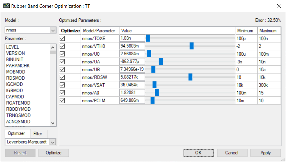
The extraction of the corner model is done by opening the Rubberband from the viewer, as shown in cor_ex04_16.png
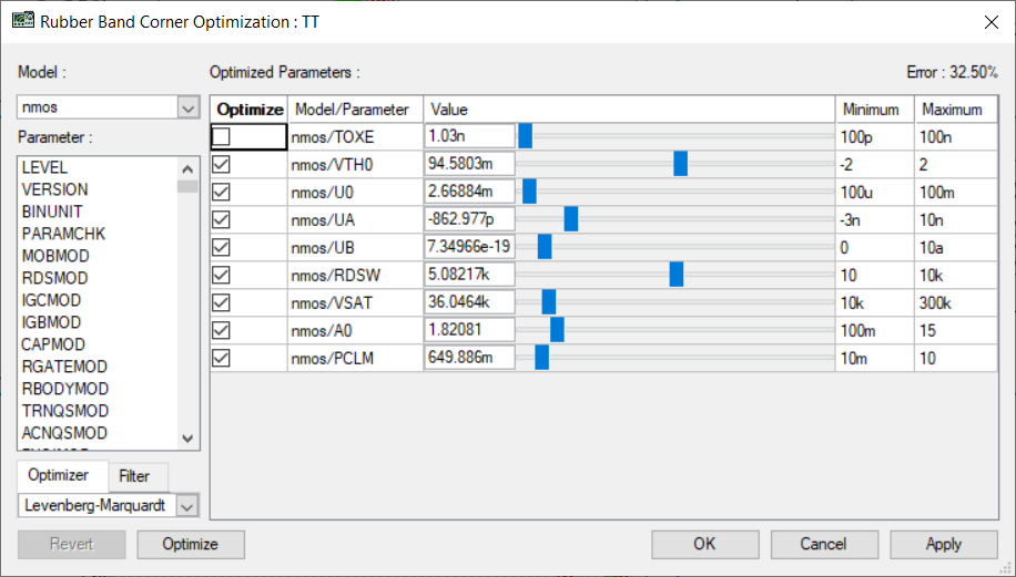
for the Typical corner case. In the Rubberband “Optimize” column we unselect the TOXE parameter, as shown in cor_ex04_17.png
, as this parameter needs to be set to its fixed value, according to the specifications. We continue by pressing the “Optimize” button in Rubberband, to optimize VTH0, U0, UA, UB, RDSW, VSAT, A0 and PCLM parameters. Once the optimization is finished, we press the “OK” button to close the Rubberband and save the values of the parameters for the “TT” corner model.
The values in the Errors table indicate that the resulting “TT” corner model meets the specifications, with just a few minor differences, that may be accepted: cor_ex04_18.png
. The plots also illustrate the good fitting of the extracted model: cor_ex04_19.png
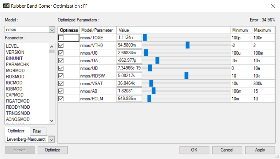
We continue by selecting the “FF” Corner from the “Select Corner” drop-down list. We show the plots for the “FF” corner and open the Rubberband from the viewer. In the Rubberband “Optimize” column we unselect the TOXE parameter, as shown in cor_ex04_20.png
. We continue by pressing the “Optimize” button in Rubberband, to optimize all parameters, except for TOXE. Once the optimization is finished, we press the “OK” button to close the Rubberband and save the values of the parameters for the “FF” corner model. The values in the Errors table indicate that the resulting “FF” corner model meets the specifications, with just a few minor differences, that may be accepted: cor_ex04_21.png
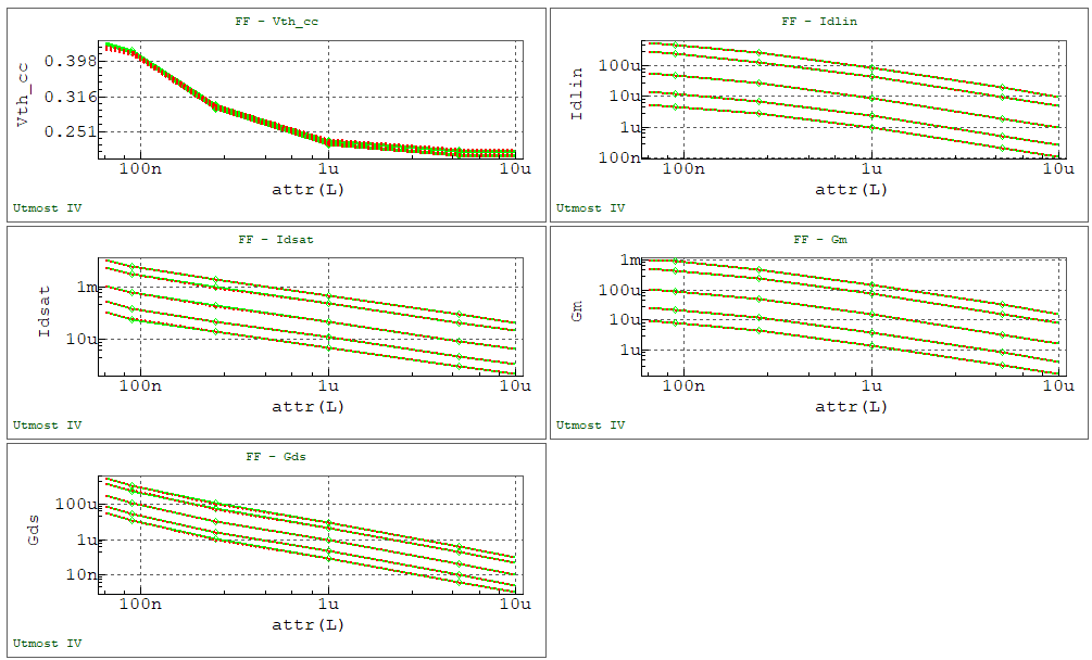
. The plots also illustrate the good fitting of the extracted model: cor_ex04_22.png
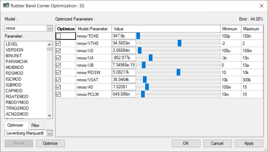
Finally, we proceed the same way for the “SS” Corner, by selecting it from the “Select Corner” drop-down list. We show the plots for the “SS” corner and open the Rubberband from the viewer. In the Rubberband “Optimize” column we unselect the TOXE parameter, as shown in cor_ex04_23.png
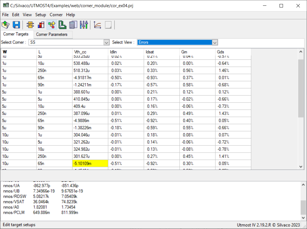
. We continue by pressing the “Optimize” button in Rubberband, to optimize all parameters, except for TOXE. Once the optimization is finished, we press the “OK” button to close the Rubberband and save the values of the parameters for the “SS” corner model. The values in the Errors table indicate that the resulting “SS” corner model meets the specifications, with just a few minor differences, that may be accepted: cor_ex04_24.png
. The plots also illustrate the good fitting of the extracted model: cor_ex04_25.png
The tuned parameters for the 3 corners can now be further examined in the Corner Parameters tab, as shown in cor_ex04_26.png
. Furthermore, a model library can be created by selecting the Corner->Write to Library menu item, which opens the “Write Library File” Dialog, as shown in cor_ex04_27.png
. One can then specify a file name and an optional prefix for the updated model parameters.
The contents of the saved library file is show in cor_ex04.lib. The parameter set for each corner are saved under corresponding libraries with the same names as the project corner names (“TT”, “FF” and “SS”, respectively. The TOXE, VTH0, U0, UA, UB, RDSW, VSAT, A0 and PCLM parameters in the model card are referring the netlist parameters defined in the corner libraries.
Graphics

Files
cor_ex04.lib
.LIB TT
.PARAM cor_TOXE_nmos = 1.03e-09
.PARAM cor_VTH0_nmos = 0.0793274
.PARAM cor_U0_nmos = 0.00307288
.PARAM cor_UA_nmos = -8.68286e-10
.PARAM cor_UB_nmos = 1.03193e-18
.PARAM cor_RDSW_nmos = 7062.86
.PARAM cor_VSAT_nmos = 82122.3
.PARAM cor_A0_nmos = 2.7167
.PARAM cor_PCLM_nmos = 2.81218
.ENDL TT

.LIB FF
.PARAM cor_TOXE_nmos = 1.1124e-09
.PARAM cor_VTH0_nmos = 0.0695519
.PARAM cor_U0_nmos = 0.00331612
.PARAM cor_UA_nmos = -8.99085e-10
.PARAM cor_UB_nmos = 7.25915e-19
.PARAM cor_RDSW_nmos = 4051.22
.PARAM cor_VSAT_nmos = 106590
.PARAM cor_A0_nmos = 2.70596
.PARAM cor_PCLM_nmos = 2.76774
.ENDL FF

.LIB SS
.PARAM cor_TOXE_nmos = 9.476e-10
.PARAM cor_VTH0_nmos = 0.110727
.PARAM cor_U0_nmos = 0.002272
.PARAM cor_UA_nmos = -8.51436e-10
.PARAM cor_UB_nmos = 9.67651e-19
.PARAM cor_RDSW_nmos = 7054.09
.PARAM cor_VSAT_nmos = 74823.5
.PARAM cor_A0_nmos = 1.73454
.PARAM cor_PCLM_nmos = 0.811999
.ENDL SS

.LIB models
.MODEL nmos NMOS (
+LEVEL    = 54             VERSION  = 4.6            BINUNIT  = 1
+PARAMCHK = 1              MOBMOD   = 1              RDSMOD   = 0
+IGCMOD   = 0              IGBMOD   = 0              CAPMOD   = 2
+RGATEMOD = 0              RBODYMOD = 0              TRNQSMOD = 0
+ACNQSMOD = 0              FNOIMOD  = 1              TNOIMOD  = 0
+DIOMOD   = 1              PERMOD   = 1              GEOMOD   = 0
+EPSROX   = 3.9
+TOXE = cor_TOXE_nmos
+DTOX     = 0              XJ       = 1.5e-07        NDEP     = 9.42239e+16
+NGATE    = 0              NSD      = 1e+20          RSH      = 0
+RSHG     = 0.1
+VTH0 = cor_VTH0_nmos
+VFB      = 1              PHIN     = -0.3074        K1       = 0.737411
+K2       = -0.117964      K3       = 279.24         K3B      = -489.377
+W0       = 1e-05          LPE0     = 1.07487e-07    LPEB     = -7.15578e-09
+DVT0     = 1.56021        DVT1     = 0.794481       DVT2     = -0.032
+DVTP0    = 0              DVTP1    = 0              DVT0W    = 0
+DVT1W    = 0              DVT2W    = -0.032         U0       = cor_U0_nmos
+UA       = cor_UA_nmos    UB       = cor_UB_nmos    UC       = 0.45946
+EU       = 1.67
+VSAT = cor_VSAT_nmos
+A0       = cor_A0_nmos    AGS      = 0.00786686     B0       = 0
+B1       = 0              KETA     = 0.13231        A1       = 0
+A2       = 1              WINT     = 1.09686e-09    LINT     = 8.5955e-09
+DWG      = -7.09648e-09   DWB      = -7.71477e-08   VOFF     = -0.118411
+VOFFL    = 0              MINV     = -0.0764226     NFACTOR  = 22.0768
+ETA0     = 0.477988       ETAB     = -0.07          DSUB     = 0.371266
+CIT      = 0              CDSC     = 0.00024        CDSCB    = 0
+CDSCD    = 0
+PCLM = cor_PCLM_nmos
+PDIBLC1  = 0.001          PDIBLC2  = 1e-05          PDIBLCB  = 0
+DROUT    = 0.829187       PSCBE1   = 4.14233e+08    PSCBE2   = 0.000386234
+PVAG     = 9.25299        DELTA    = 0.00465946     FPROUT   = 0
+PDITS    = 0              PDITSL   = 0              PDITSD   = 0
+LAMBDA   = 0              VTL      = 205000         LC       = 0
+XN       = 3
+RDSW = cor_RDSW_nmos
+RDSWMIN  = 369.532        RDW      = 100            RDWMIN   = 0
+RSW      = 100            RSWMIN   = 0              PRWG     = 4.36516
+PRWB     = -0.839777      WR       = 1              ALPHA0   = 0
+ALPHA1   = 0              BETA0    = 30             AGIDL    = 0
+BGIDL    = 2.3e+09        CGIDL    = 0.5            EGIDL    = 0.8
+AIGBACC  = 0.43           BIGBACC  = 0.054          CIGBACC  = 0.075
+NIGBACC  = 1              AIGBINV  = 0.35           BIGBINV  = 0.03
+CIGBINV  = 0.006          EIGBINV  = 1.1            NIGBINV  = 3
+AIGC     = 0.0136         BIGC     = 0.00171        CIGC     = 0.075
+DLCIG    = 0              NIGC     = 1              POXEDGE  = 1
+PIGCD    = 1              NTOX     = 1              TOXREF   = 3e-09
+XPART    = 0              CGSO     = 6.19328e-10    CGDO     = 6.19707e-10
+CGSL     = 2.53081e-10    CGDL     = 2.52918e-10    CKAPPAS  = 0.0255362
+CKAPPAD  = 0.0248237      CLC      = 1e-07          CLE      = 0.6
+DLC      = 0              DWC      = 0              VFBCV    = -1
+NOFF     = 1              VOFFCV   = 0.162526       ACDE     = 1
+MOIN     = 15             XRCRG1   = 12             XRCRG2   = 1
+RBPB     = 50             RBPD     = 50             RBPS     = 50
+RBDB     = 50             RBSB     = 50             GBMIN    = 1e-12
+NOIC     = 8.75           EM       = 4.1e+07        AF       = 1
+EF       = 1              KF       = 0              NTNOI    = 1
+TNOIA    = 1.5            TNOIB    = 3.5            RNOIA    = 0.577
+RNOIB    = 0.37           DMCG     = 0              DMCI     = 0
+DMDG     = 0              DMCGT    = 0              DWJ      = 0
+XGW      = 0              XGL      = 0              XL       = 0
+XW       = 0              NGCON    = 1              IJTHSREV = 0.1
+IJTHDREV = 0.1            IJTHSFWD = 0.1            IJTHDFWD = 0.1
+XJBVS    = 1              XJBVD    = 1              BVS      = 10
+BVD      = 10             JSS      = 0.0001         JSD      = 0.0001
+JSWS     = 0              JSWD     = 0              JSWGS    = 0
+JSWGD    = 0              CJS      = 0.0005         CJD      = 0.0005
+MJS      = 0.5            MJD      = 0.5            MJSWS    = 0.33
+MJSWD    = 0.33           CJSWS    = 5e-10          CJSWD    = 5e-10
+CJSWGS   = 5e-10          CJSWGD   = 5e-10          MJSWGS   = 0.33
+MJSWGD   = 0.33           PB       = 1              PBSWS    = 1
+PBSWD    = 1              PBSWGS   = 1              PBSWGD   = 1
+TNOM     = 27             UTE      = -0.623226      KT1      = -0.660124
+KT1L     = 2.02929e-08    KT2      = -0.178646      UA1      = 1.14212e-09
+UB1      = 2.92892e-19    UC1      = -0.0687707     AT       = 86944.8
+PRT      = 9.99937        NJS      = 1              NJD      = 1
+XTIS     = 3              XTID     = 3              TPB      = 0
+TPBSW    = 0              TPBSWG   = 0              TCJ      = 0
+TCJSW    = 0              TCJSWG   = 0              SAREF    = 1e-06
+SBREF    = 1e-06          WLOD     = 0              KU0      = 0
+KVSAT    = 0              TKU0     = 0              LKU0     = 0
+WKU0     = 0              LLODKU0  = 0              WLODKU0  = 0
+KVTH0    = 0              LKVTH0   = 0              WKVTH0   = 0
+LLODVTH  = 0              WLODVTH  = 0              STK2     = 0
+LODK2    = 1              STETA0   = 0              LODETA0  = 1
+WL       = 0              WLN      = 1              WW       = 0
+WWN      = 1              WWL      = 0              LL       = 0
+LLN      = 1              LW       = 0              LWN      = 1
+LWL      = 0              LLC      = 0              LWC      = 0
+LWLC     = 0              WLC      = 0              WWC      = 0
+WWLC     = 0              LMIN     = 0              LMAX     = 1
+WMIN     = 0              WMAX     = 1              AIGS     = 0.0136
+BIGS     = 0.00171        CIGS     = 0.075          AIGD     = 0.0136
+BIGD     = 0.00171        CIGD     = 0.075          DLCIGD   = 0 )
.ENDL models