

Minimum Required Version
: Expert 4.14.0.R, Guardian 4.14.0.R
This example demonstrates how a Boolean
NOT
function operates when using two layers. The
NOT
logical operator is typically used in Guardian DRC or Guardian LVS to generate additional (derived) layers that will be used in other operations. In Guardian, the Boolean
NOT
operation is performed by the
DIF
command.
1. Preliminary steps
To run this example, open a Guardian DRC session and choose
File->Open
to load the project “dif_ex06.eld”. Then in the Open Cell(s) form that pops up, select “dif_ex06” and select “OK”.
2. Boolean NOT (subtraction) operation between two layers
The
DIF
command is used when developers need to generate the difference between two existing layers. The
DIF
command returns Layer1 shapes that do not intersect with Layer2 shapes.
The
DIF
syntax is as follows:
   DIF: Layer1=< input layer identifier1 >,
        Layer2=< input layer identifier2 >,
        LayerR=< result layer identifier >;
Two examples of using the
DIF
operator will be discussed. The first example is based on the
DIF
illustration shown in Figure 2-18 of the Guardian User Manual.
Example 1
The example cell “dif1_ex06” provided in the “dif_ex06.eld” project illustrates how to use the
DIF
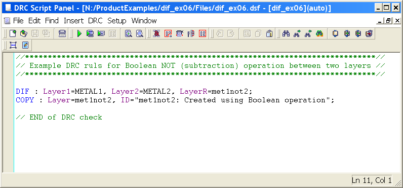
operator with two layers. An example rule file is shown in
Figure 1
. It uses the “METAL1” and “METAL2” layers to create a new layer called “met1not2”. The “Copy” is not necessary, but is used to store the newly generated shape(s) into the layout in order see the results of the
DIF
operation.
Example 2
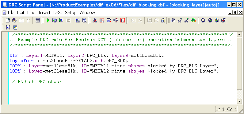
The second example, “dif2_ex06”, illustrates how to use a blocking layer to ignore or block shapes from being processed during DRC operations. Users may need or want to eliminate portions of their designs from being checked. For instance, a logo or other area of the layout may need to be ignored or not checked. One method is to add a blocking layer over the area to be ignored. An example rule file is shown in
Figure 2
, which illustrates how to accomplish this task.
Looking at the rule file, the
DIF
operator creates a new layer by returning Layer1 shapes that do not intersect with Layer2 shapes. The first
DIF
statement returns all “METAL1” shapes that do not intersect with the blocking layer “DRC_BLK” and generates a new layer called “met1LessBlk”. Similarly, the second
DIF
statement does the same operation using “METAL2”, but uses the Logicform command to illustrate the Logicform syntax of the same operation.
The two “Copy” commands are not necessary, but are used to store the newly generated shape(s) into the layout in order see the results of the
DIF
operation.
3. Experimenting with Boolean DIF function
Once all the example files have been downloaded and the preliminary steps describes in section 1.0 are completed, xomplete the following steps:
Example 1 Results
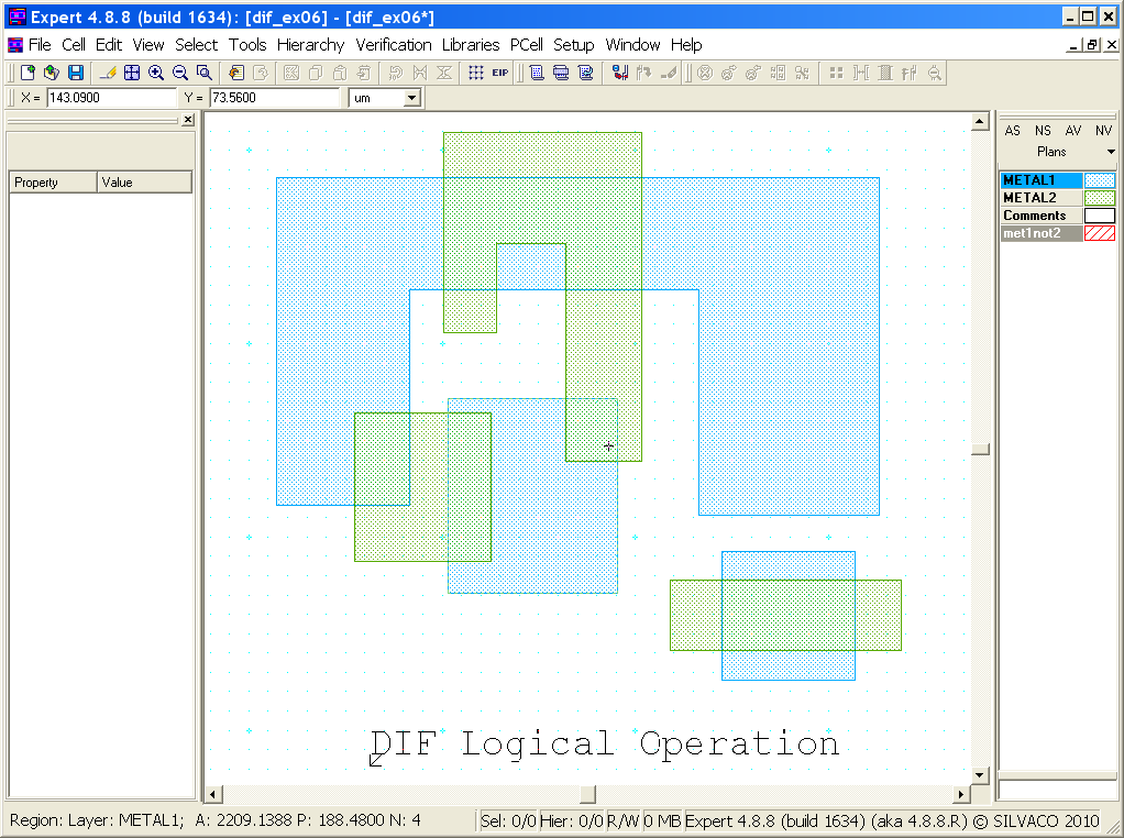
The original layout is shown in
Figure 3
. It contains three shapes on METAL1 and METAL2 that intersect each other. To review the results:
- Choose
Verification->DRC->DRC Script panel
. In the new window, choose
File->Open
… and select “dif_ex06.dsf”. - In the same window, choose
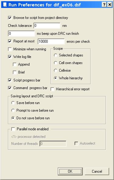
Setup->Current DRC script run preferences
… and set the options as shown in
Figure 4
. - Accept the changes and press
DRC->Run
. - To inspect the newly generated shape(s), make the “met1not2” layer active and then turn off all remaining layers using the “NV” button. (To make the “met1not2” layer active, click on the layer`s color strip which contains the check mark).
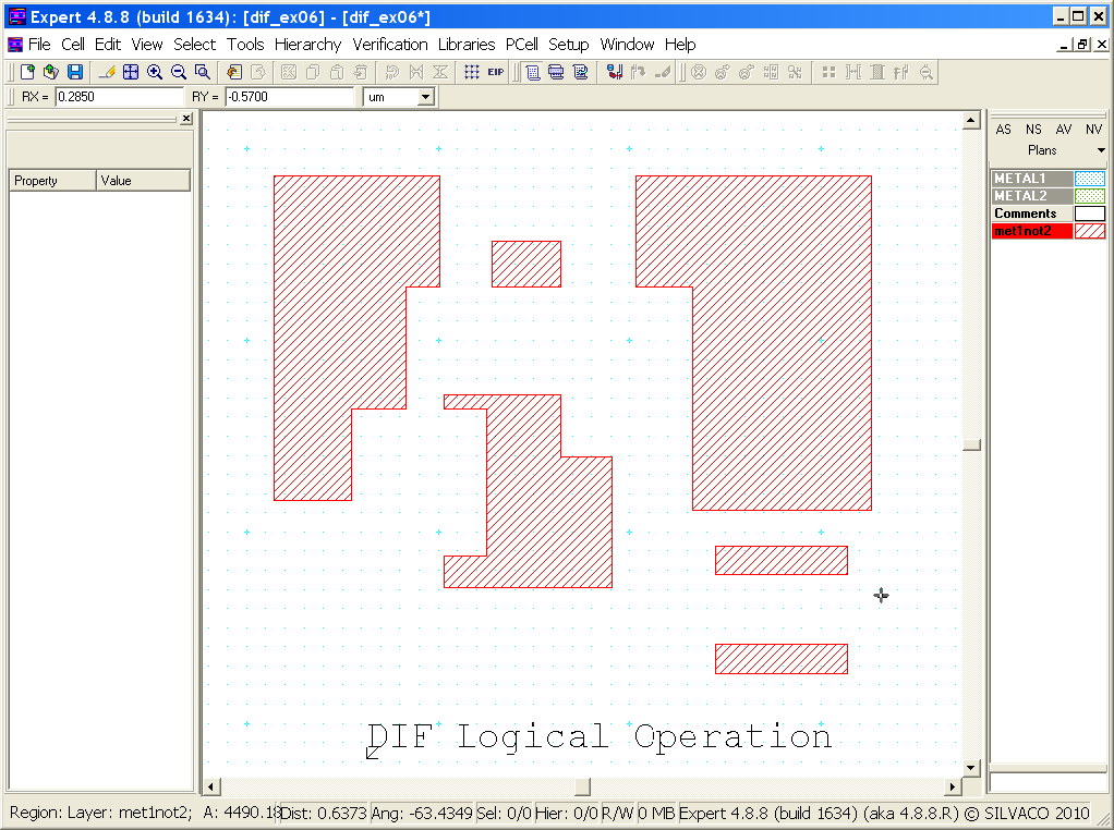
Figure 5
shows the resulting shapes from the
DIF
operation. Notice how the new layer “met1not2” only contains “METAL1” shapes that did not intersect with “METAL2” shapes. The new layer only contains the “METAL1” shapes that are different or not in common with the “METAL2” shapes.
Example 2 Results
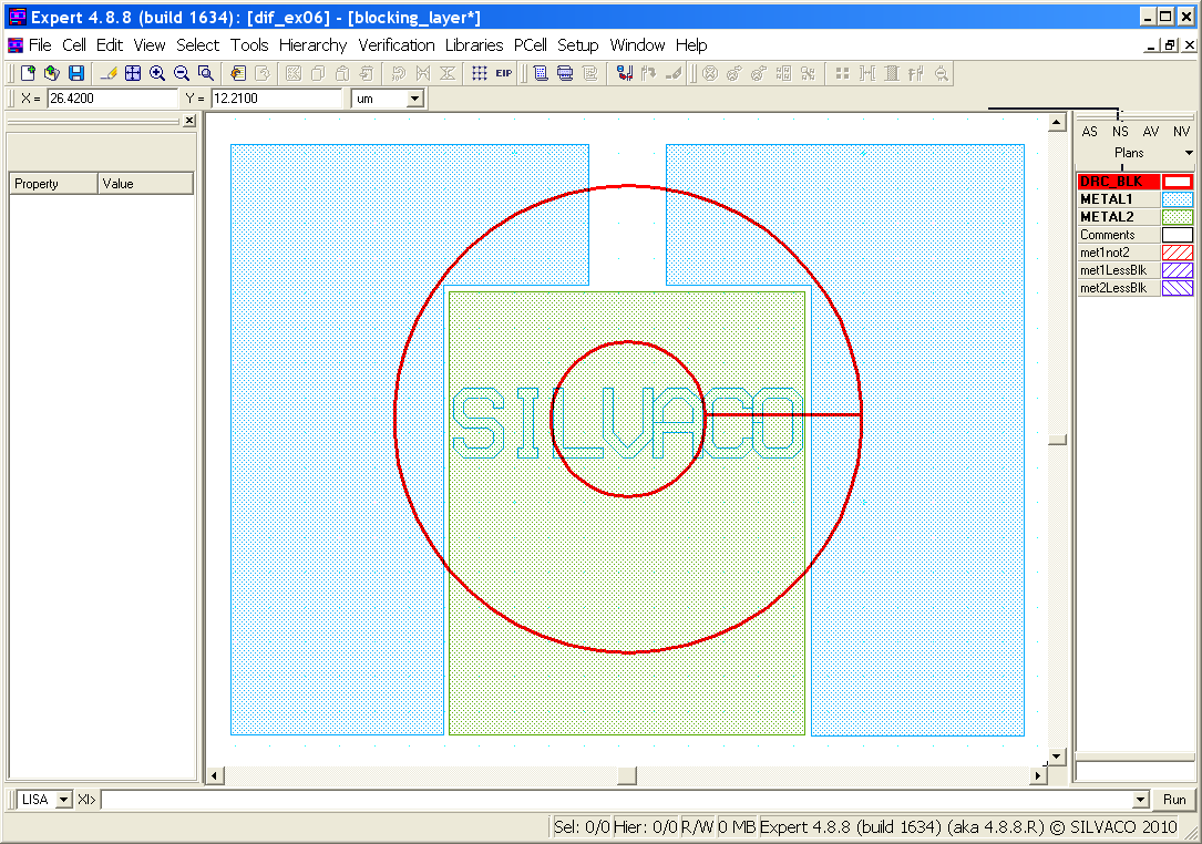
The original layout is shown in
Figure 6
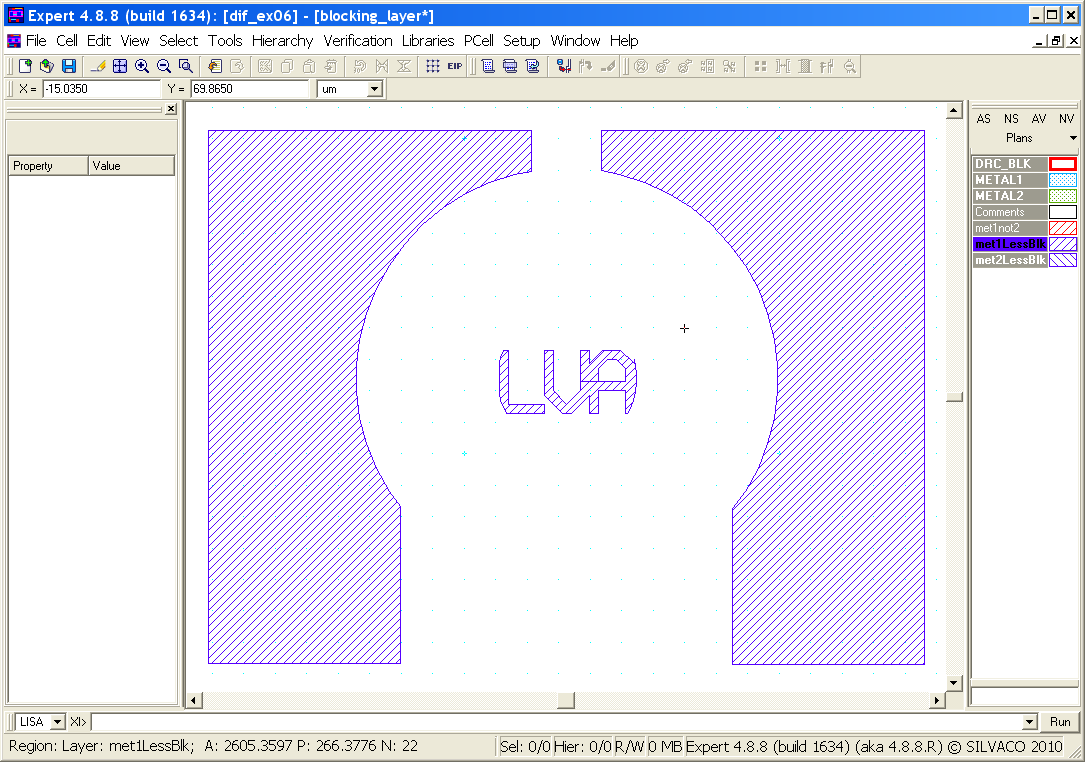
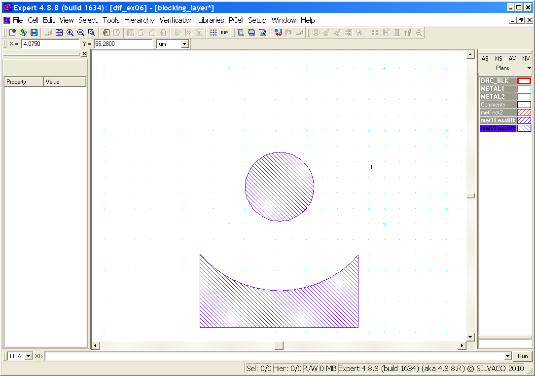
. The results for “METAL1” and “METAL2” are shown in
Figure 7
, and
Figure 8
, respectfully. Repeat the above steps, but use the “dif_blocking.dsf” rule file as input to Guardian DRC. Toggle between the active layers to see the results. Notice how the “met1LessBlk” and “met2LessBlk” layers were formed when the blocking layer overlapped the “METAL1” and “METAL2” layers.
To learn more about Guardian DRC commands and their syntax, see the Guardian DRC user manual “guardian_users1.pdf” located in lib/expert/4.14.0.R/docs/ in your installation area.
Output Results
Input Files
dif_blocking.dsf
//*****************************************************************************//
// Example DRC ruls for Boolean NOT (subtraction) operation between two layers //
//*****************************************************************************//

DIF : Layer1=METAL1, Layer2=DRC_BLK, LayerR=met1LessBlk;
Logicform : met2LessBlk=METAL2.dif.DRC_BLK;
COPY : Layer=met1LessBlk, ID="METAL1 minus shapes blocked by DRC_BLK Layer";
COPY : Layer=met2LessBlk, ID="METAL2 minus shapes blocked by DRC_BLK Layer";

// END of DRC check
dif_ex06.dsf
//*****************************************************************************//
// Example DRC ruls for Boolean NOT (subtraction) operation between two layers //
//*****************************************************************************//

DIF : Layer1=METAL1, Layer2=METAL2, LayerR=met1not2;
COPY : Layer=met1not2, ID="met1not2: Created using Boolean operation";

// END of DRC check