

Minimum Required Version
: Expert 4.14.0.R, Guardian 4.14.0.R
This example shows usage of the antenna check.
To check the antenna characteristics for nodes,
Guardian DRC
provides the following two commands in addition to the connectivity statements.
-
Get_Node_Params:
This operation is used to extract geometric parameters from the input layer
for each electrical node, and generate the result file specified by the
output layer parameter. It is to be used as
the File input parameter for the Check_Node_Params statement. -
Check_Node_Params:
The operation checks geometric parameters extracted by the Get_Node_Params
statement on each electrical node present in the input parameter files.
This example can check the ratio between the area of the interconnect layer “FPOLY” and the area of the gate layer “GATE” larger than 100 using the following descriptions:
   // Get Area information of GATE
   Get_Node_Params: Options = (Area),
                    Layer   = GATE_STM,
                    LayerR  = GATE_TRAITS;
   // Get Area information of FPOLY
   Get_Node_Params: Options = (Area),
                    Layer   = FPOLY,
                    LayerR  = FPOLY_TRAITS;
   // Check (Area of FPOLY) / (Area of GATE)  > 100
   Check_Node_Params:
          Formula = (sum.FPOLY_TRAITS.Area / sum.GATE_TRAITS.Area),
                      Limits >100,
                      Layer   = POLY,
                      LayerR  = BAD_POLY;
                      LogR    = antenna_check_LogR.ant,
                      LogA    = antenna_check_LogA.ant;
Please refer to
antenna_check.dsf for details.
To run the example it needs:
1) Start Guardian DRC or Expert
2) Load
“antenna_check.eld”
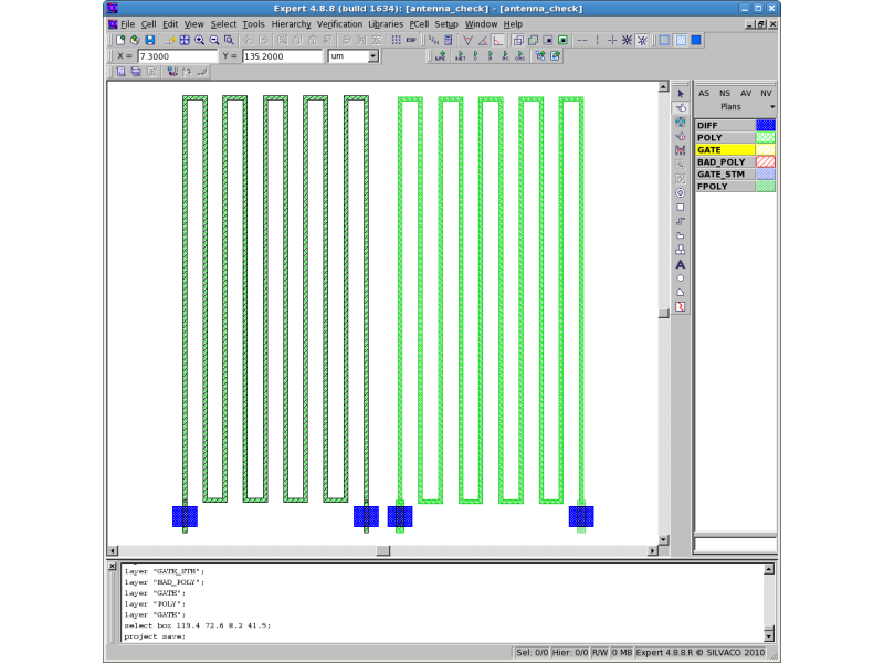
and open the “antenna_check” cell
(
File->Open
).
See
antenna_check_lay.png
3) Load the
“antenna_check.dsf”
script from the Script panel
(Verification->DRC->DRC Script Panel).
4) Run DRC
(DRC->Run).
5) View DRC errors
(select DRC->Errors->Load Errors and click “Load” in the Load DRC Errors dialog).
See
antenna_check_error.png
As a result, a layer -BAD_POLY- will be created with a geometry, which violates antenna checks
in only the left side of the layout, because “FPOLY” on the right side of the layout is
connected with the “GATE” layers whose area is two times larger than the left side one.
antenna_check_LogR.ant is the output geometry log file.
antenna_check_LogA.ant is the antenna violation log file.
To learn more about Guardian DRC commands and their syntax, see the Guardian DRC user manual “guardian_users1.pdf” located in lib/expert/4.14.0.R/docs/ in your installation area.
Output Results

Input Files
antenna_check.dsf
Update_layout: Node_Attr_Name=DcrNode, Antenna_Attr_Name=DrcAntenna;

Connect: Layers=(POLY);

//////////////////////////////
//  Example: Antenna Rules  //
//////////////////////////////
// Get GATE layer
And: Layer1=POLY, Layer2=DIFF, LayerR=GATE;

// Select GATE region
Select:
  Relation = STAMP,
  Options  = (Touch-),
  Layer1   = GATE,
  Layer2   = POLY,
  LayerR   = GATE_STM;

// Get interconnect Poly
Dif:
  Layer1 = POLY,
  Layer2 = GATE,
  LayerR = FPOLY;

// For Antenna Check
// Get Area information of GATE
Get_Node_Params:
  Options = (Area),
  Layer   = GATE_STM,
  LayerR  = GATE_TRAITS;

// Get Area information of FPOLY
Get_Node_Params:
  Options = (Area),
  Layer   = FPOLY,
  LayerR  = FPOLY_TRAITS;

// Check (Area of FPOLY) / (Area of GATE)  > 100
Check_Node_Params:
  Formula = (sum.FPOLY_TRAITS.Area / sum.GATE_TRAITS.AreA),
  Limits > 100,
  Layer   = POLY,
  LayerR  = BAD_POLY,
  LogR    = antenna_check_LogR.ant,
  LogA    = antenna_check_LogA.ant;
Copy: Layer = BAD_POLY, ID = "antenna: @Maximum ratio of FPOLY area to GATE area 100";
antenna_check_LogA.ant
command #7: Check_Node_Params
Formula: sum.FPOLY_TRAITS.Area/sum.GATE_TRAITS.AreA
Script Unit = 1um

VIOLATIONS:
Node Number   Formula Value
          1 : 105.1
antenna_check_LogR.ant
command #7: Check_Node_Params
Formula: sum.FPOLY_TRAITS.Area/sum.GATE_TRAITS.AreA
DB Unit = 0.0001um
Script Unit = 1um

VIOLATIONS:
       Lower Left Vertex         Antenna Value
                                 (accumulated)
X=      95,000  Y=     295,000 : 105.1
X=     545,000  Y=     220,000 : 105.1
X=      95,000  Y=     220,000 : 105.1