Minimum Required Versions: Gateway 2.12.10.R, SILOS 4.10.90.R
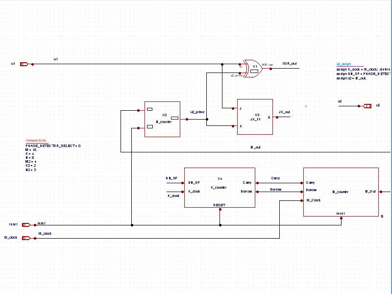
Example 2 is an all digital PLL schematic design (
all_digital_PLL.png
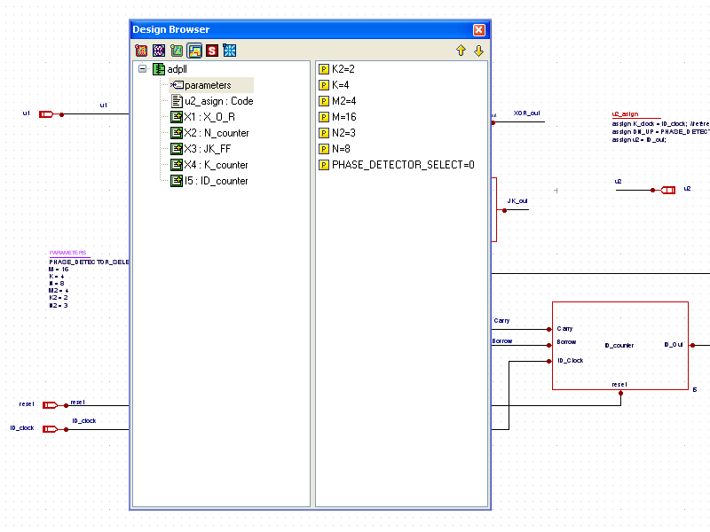
). In the design browser, clickING on the parameters entry displays the parameter
names and values (
parameter.png
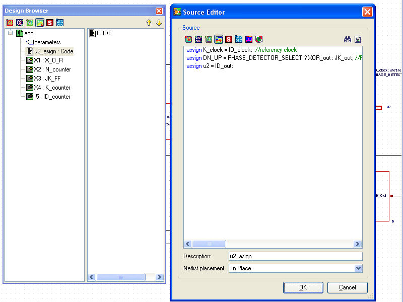
) that the module will use in the netlist. Clicking on the CODE entry for the next item down in the list shows the contents of the CODE block (
block.png
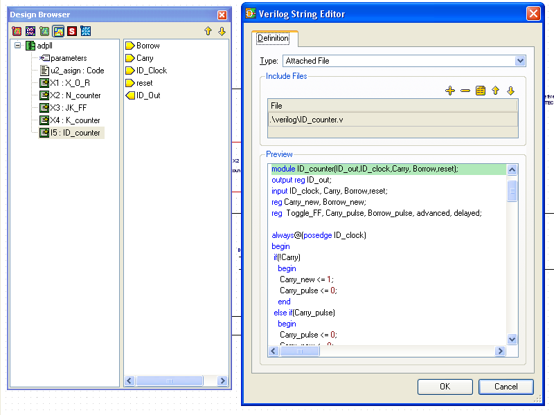
), which in this case are the assign statements required for the module. Right clicking on any of the other instances in the design provides the menus for viewing the module definition. For instance, right clicking on the I5 instance in the design browser, and choosing Goto Definition shows the
definition for the ID_counter module (
module.png
).
Clicking on the Netlist button generates the verilog
netlist for the design (
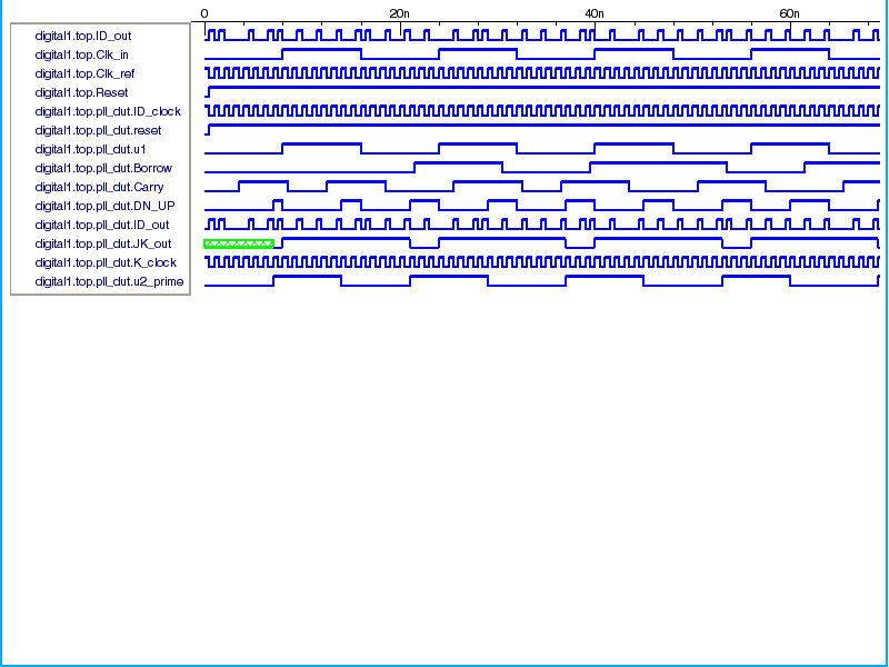
adpll.v). Running the simulation produces a digital raw file where the waveforms
can be viewed and processed (
waveforms.png
).
Graphics