Requires: Utmost IV, SmartSpice, SmartView
Minimum Versions: Utmost IV 1.10.6.R, SmartSpice 4.10.6.R, SmartView 2.28.2.R
This example describes how to perform capacitance measurements including
calibration and de-embedding.
The project file
acq_ex09.prj
for this example should be loaded into your database. When opened, the
project will look as shown in
acq_ex09_01.png
.
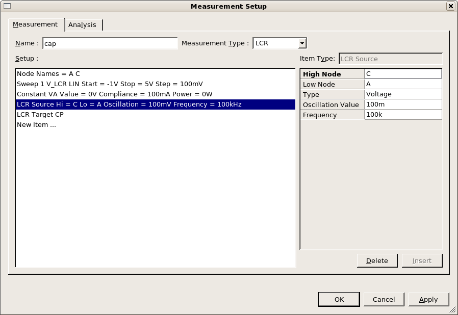
This project is already set up to measure a diode capacitance using the measurement
setup as shown in
acq_ex09_02.png
. In this measurement setup, the cathode is connected to the Hi terminals of the LCR
instrument and the anode connected to the Lo terminals. Therefore, positive bias from
the LCR instrument (V_LCR) will reverse bias the diode.
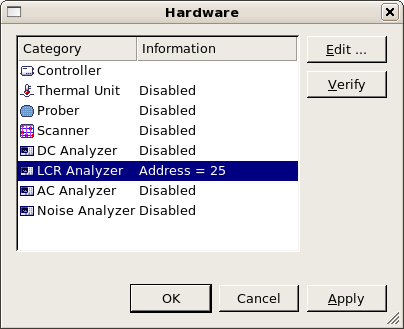
In the hardware dialog, the LCR instrument is enabled as shown in
acq_ex09_03.png
. The LCR instrument provides the DC bias for this measurement internally.
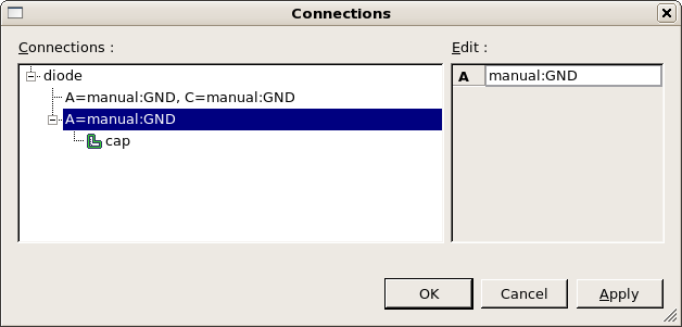
In the connections dialog, shown in
acq_ex09_04.png
, you can see the connection for this capacitance measurement. The bias on
the Hi terminals is supplied by the LCR instrument itself. The LCR
instrument also has a virtual ground on the Lo terminals, therefore no
DC instrument is required to supply the zero volts ground on the anode.
In the connection, the anode is set to ‘manual:GND’ to indicate that this
ground is already taken care of.
When measuring any capacitance, you should calibrate or zero the LCR
instrument to remove the effect of the test instrument, cables, probes,
test structure, etc. from the measured result. If you have a dedicated
open calibration structure, this should be used when calibrating the
LCR instrument.
To calibrate the LCR instrument, select the capacitance measurement setup
in the measurement sequence and then select
Measure->Calibrate
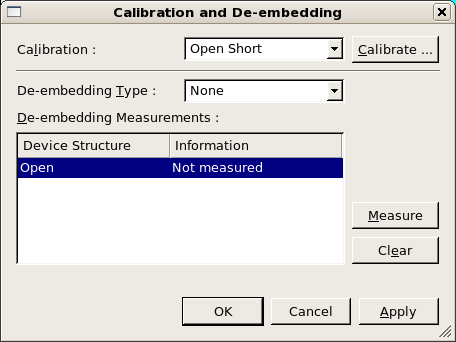
from the menu. This will open the calibration and de-embedding dialog as shown in
acq_ex09_05.png
.
For capacitance measurements, we only need to perform the open correction
to the LCR instrument. Clicking on the
Calibrate
button will open up
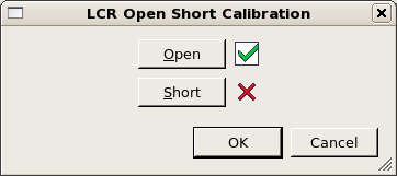
LCR Open Short Calibration
dialog. From this dialog, clicking the
Open
button will perform the instrument calibration. This may take several minutes
depending on the LCR instrument. When the calibration completes sucessfully,
this is indicated on the dialog as shown in
acq_ex09_06.png
.
Some older equipment does not have a calibration option. In this case, you
should perform a de-embedding measurement on the open structure. This
measured open data will then be subtracted from the device result automatically
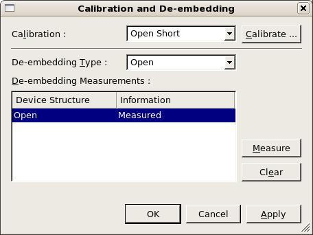
when you perform the measurement. To perform an open de-embedding measurement,
select the
De-embedding Type
to be
Open
. Then select the open device structure and click on the
Measure
button in the dialog. When the open de-embedding measurement
is completed, this will be displayed in the calibration dialog
as shown in
acq_ex09_07.png
.
Another reason you may need to use the de-embedding feature is if you have
a problem with your test structure. If, after calibation, you measure the
open structure and it has a significant bias dependent capacitance over
the voltage range you want to measure, then you can use open de-embedding
to correct for this in the device measurement.
Note that when you are using the de-embedding feature, you must
Save
or
Apply
before closing the calibration dialog, otherwise the de-embedding measurement
will be lost.
Once you have performed your calibration to zero the LCR instrument and, if
necessary, have performed the open de-embedding measurement, you are now ready
to measure the device capacitance characteristic. This is done by selecting
Measure->Run
from the menu to run the measurement sequence as normal. If you have selected
to perform open de-embedding, the open data will be automatically subtracted
from the device capacitance measurement.
Graphics