Requires: Utmost IV, SmartSpice, SmartView
Minimum Versions: Utmost IV 1.10.6.R, SmartSpice 4.10.6.R, SmartView 2.28.2.R
In order to perform real measurements using real measurement instruments, it is
necessary to describe your hardware configuration and to verify that everything is
working as expected. This example describes how to set up the controller and the
instruments which make up the hardware and to verify that they are connected
correctly.
The project file
acq_ex07.prj
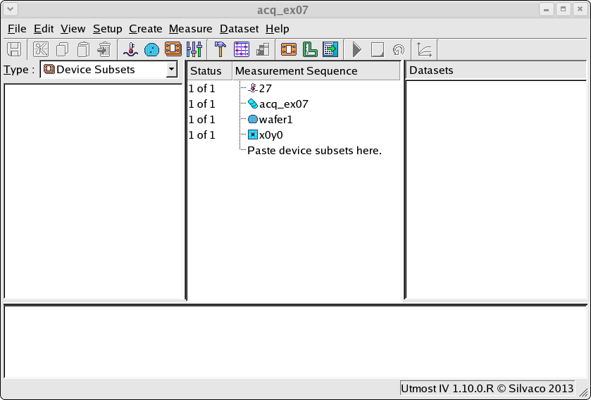
for this example should be loaded into your database. When opened, the
project will look as shown in
acq_ex07_01.png
. This project is in measurement mode, which enables the project
Hardware.
Selecting
Setup->Hardware
in the menu will open the hardware configuration dialog as shown in
acq_ex07_02.png
. The hardware consists of one controller and many instruments.
The measurement instruments communicate using a GPIB interface. Most computers
do not have a GPIB interface capability. Therefore, we use an external controller
in order to talk to the instruments. This example uses a National Instruments
RS232 to GPIB controller. This controller is connected on the instrument side to
the GPIB interface and on the computer side to the RS232 port of the computer.
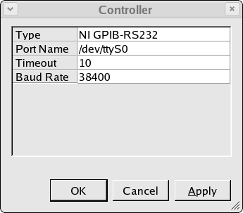
acq_ex07_03.png
shows how this RS232 to GPIB controller is configured on our system. The port
name is the name of the RS232 port file on our linux computer and the baud rate
must match to the baud rate setting of the external RS232-GPIB controller box.
Remember to switch off and on the controller box if you change any settings for
the box to be reconfigured correctly.
Once the controller is configured, then from the hardware dialog you can select
the controller and
Verify
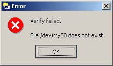
that the configuration is correct. If the port name is not present on your
system, then you would see the following error message
acq_ex07_04.png
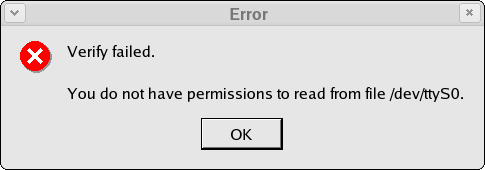
. If the port name is present, but you do not have the correct permissions to
read from and write to the port, then you will see the following error message
acq_ex07_05.png
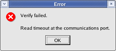
. If you do not connect the controller to the correct port, or if the baud rate
does not match to the settings of the external controller box, this will cause a
timeout to occur and you will see the following error message
acq_ex07_06.png
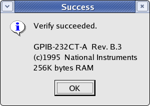
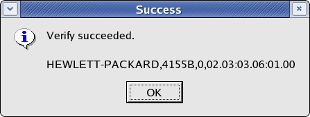
. If everything is correctly configured and connected, then the verify will succeed
and you will see a message like the following
acq_ex07_07.png
.
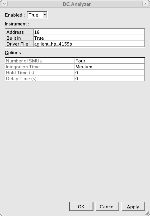
Once the controller is verified and working correctly, then you can connect to
various measurement instruments. In this example we will connect to a DC analyzer.
Select
DC Analyzer
from the hardware menu and press
Edit
to edit the configuration of the DC measurement instrument which is shown in
acq_ex07_08.png
.
The instrument should be enabled, the GPIB address of the instrument should be
set and the correct driver for your measurement instrument should be selected
from the built in pull down list. The driver is the software which is used to
talk to the instrument.
Once you have selected the driver you are using, the options for this particular
instrument will be shown in the
Options
table and you can modify these option values. For example, the agilent_hp_4155b
instrument has an option to select the
Integration Time
. You can select
Short, Medium
or
Long
for the integration time.
Once the instrument is configured, then from the hardware dialog we can select
the instrument and
Verify
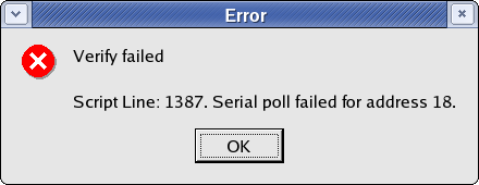
that the configuration is correct. If the GPIB address is incorrect, the instrument
is not connected to the controller or the instrument is not switched on, then you
will see the following error message
acq_ex07_09.png
. If everything is correctly configured and connected, then the verify will succeed
and you will see a message like the following
acq_ex07_10.png
.
When performing acquisition in measurement mode using real instruments, it is strongly
advised to
Verify
your controller and all instruments which will be used.
Graphics