

Minimum Required Versions: Gateway 2.12.10.R, SILOS 4.10.90.R
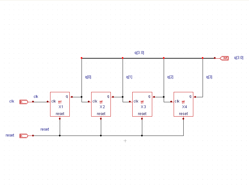
Example 4 is a four bit ripple carry counter schematic. The top level
of the design (
top_level.png
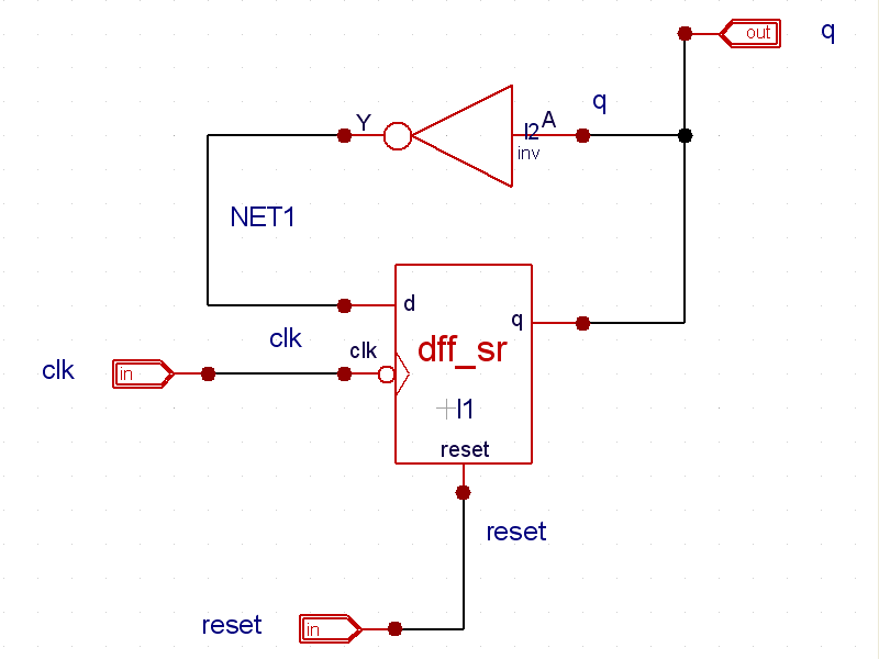
) is made from negative edge-triggered T flip flops. Descending one level down, the
schematic (
tff.png
) is built with inverters and negative edge-triggered DFFs. The inverter and DFF cells both use attached file module definitions.
The module definition for the DFF with synchronous reset is shown in
dff_sr.v. The stimulus module, or test bench, is shown in the
ripple_carry_counter.ctrv
file (
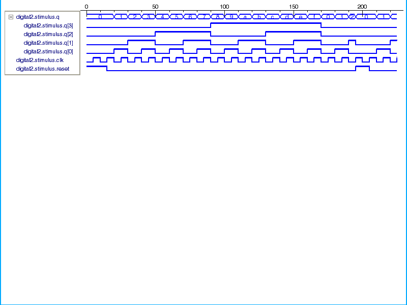
ripple_carry_counter.ctrv). In this file, the top level design is instantiated and the output is monitored. Finally, the output
waveforms are shown for the simulation (
waveforms.png
).
Graphics
Input Files
dff_sr.v
//module dff_sr with synchronous reset
module dff_sr(q, d, clk, reset);

output q;
input d, clk, reset;
reg q;

always @(posedge reset or negedge clk)
if (reset)
   q= 1'b0;
else
   q=d;

endmodule
ripple_carry_counter.ctrv
module stimulus;

reg clk;
reg reset;
wire[3:0] q;

// instantiate design block
ripple_carry_counter r1(.q(q), .clk(clk), .reset(reset));

//control the clk signal that drives the design block.. cycle time=10
initial
    clk = 1'b0; //set the clk to 0
always
    #5 clk = ~clk; // toggle clk every 5 time units

//control the reset signal that drives the design block

initial
begin
    reset = 1'b1;
    #15 reset = 1'b0;
    #180 reset = 1'b1;
    #10 reset = 1'b0;
    #20 $finish;  // end the simualtion
end

// monitor the outputs
initial
    $monitor($time, " output q = %d", q);

endmodule