Guardian DRC vs. Other DRC Systems, I
1. Introduction
This article begins a series of articles that describe the compatibility of Guardian DRC system[1] in terms of functionality: command set, syntax and implementation with other leading industrial DRC systems. The purpose of this series is to facilitate the usage of Guardian DRC system by the designers who are already familiar with some other DRC systems.
Schematic Driven Layout
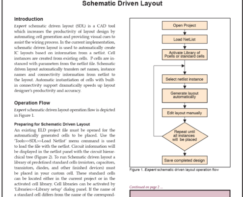
Expert schematic driven layout (SDL) is a CAD tool which increases the productivity of layout design by automating cell generation and providing visual cues to assist the wiring process. In the current implementation, schematic driven layout is used to automatically create IC layouts based on information from a netlist. Cell instances are created from existing cells.
Interactive P-cell Generation
1. Abstract
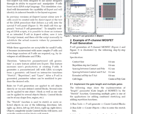
Parameterized cells (P-cells) significantly increase the productivity of layout designers. Silvaco International’s tool Expert has been designed to aid layout designers through its ability to support and manipulate P-cells based on its LISA script language. This simulation standard will demonstrate the capability of Expert and will identify its inherent benefits to the layout engineer.
Interconnect Parasitic Accuracy & Speed Improvements in New CLEVER Release
Introduction
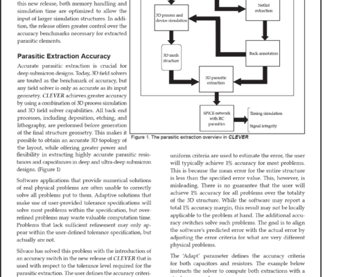
This article introduces the new features and numerical schema implemented in the most recent release of Clever from Silvaco. In this new release, both memory handling and simulation time are optimized to allow the input of larger simulation structures. In addition, the release offers greater control over the accuracy benchmarks necessary for extracted parasitic elements.
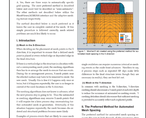
Is there a way to automatically specify mesh spacing in ATHENA?
Q. Is there a way to automatically specify mesh spacing in ATHENA?
A. Yes, there are three ways to automatically specify grid spacing. The most preferred method is described below and could best be described as “semi-automatic”. The other methods not described below utilize the MaskViews/ATHENA interface and the adaptive meshing feature respectively.
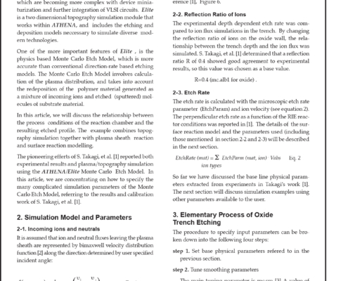
Topography Simulation of Trench Etch Using Monte Carlo Plasma Etch Model with Polymer Re-deposition
1. Introduction
The topography simulation module, Elite has constantly been improved in order to simulate advanced processes, which are becoming more complex with device miniaturization and further integration of VLSI circuits. Elite is a two dimensional topography simulation module that works within ATHENA, and includes the etching and deposition models neccessary to simulate diverse modern technologies.
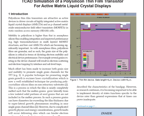
TCAD Simulation of a Polysilicon Thin Film Transistor For Active Matrix Liquid Crystal Displays
Polysilicon thin film transistors are attractive as active devices in driver circuits of highly integrated active-matrix liquid crystal displays (AMLCDs) and as p-channel metal-oxide-semiconductor field effect transistors (MOSFETs) in static random access memory (SRAM) cells.
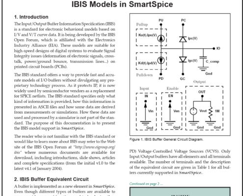
IBIS Models in SmartSpice
The Input/Output Buffer Information Specification (IBIS) is a standard for electronic behavioral models based on I/V and V/T curve data. It is being developed by the IBIS Open Forum, which is affiliated with the Electronics Industry Alliance (EIA). These models are suitable for high-speed designs of digital systems to evaluate Signal Integrity issues (deformation of electronic signals, cross-talk, power/ground bounce, transmission lines...) on printed circuit boards (PCBs).
New Features in SmartSpice 2.3.4.C
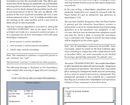
A powerful new feature “Stop-Continue” has been added to SmartSpice to allow the user to suspend a transient simulation and investigate the output before resuming the simulation run from the suspended state. This allows generated data checks during the simulation run and therefore ensuring relevant simulation data is generated. This feature allows a user to check intermediate simulation results and/or save (if necessary) on the fly.
Spectre® Replacement in the Cadence Flow
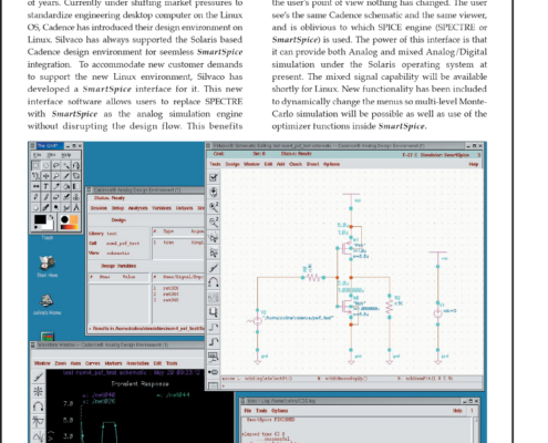
Silvaco has always supported the Solaris based Cadence design environment for seemless SmartSpice integration. To accommodate new customer demands to support the new Linux environment, Silvaco has developed a SmartSpice interface for it. This new interface software allows users to replace Spectre with SmartSpice as the analog simulation engine without disrupting the design flow.
