opt_ex24 : Using the Project Template feature to extract a PSP model
Requires: Utmost IV, SmartSpice, SmartView
Minimum Versions: Utmost IV 2.10.0.R, SmartSpice 4.38.0.R, SmartView 2.34.0.R.
This example describes how to use the Project Template feature to easily create and run an optimization project in order to extract a a global PSP model. To extract a model which is scalable with geometry, multiple different device sizes must be included. In this example, twelve different geometry devices for DC and two geometry devices for capacitance at room temperature are included.
The Project Template process includes 4 steps, as described below.
Step 1: Loading a dataset
If running Utmost IV in file mode, select File->Dataset File from the menu and load the opt_ex16.uds data file. After this file has been loaded, the Utmost IV window will look as shown in opt_ex24_optimization_mode.png .
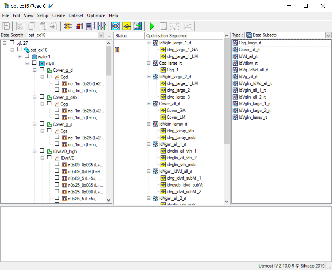
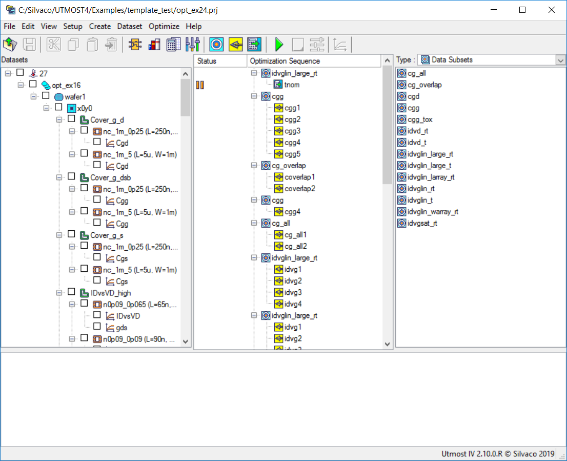
If running Utmost IV in database mode, open the opt_ex16 optimization example: opt_ex24_database_mode.png .
Step 2: Selecting a project template
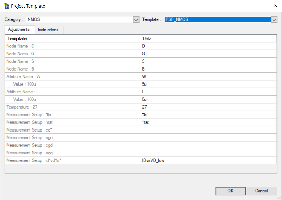
Select File->Project Template from the Utmost IV menu. This will open the Project Template Dialog window. Select the "NMOS" category and the "PSP_NMOS" template. The Project Template dialog window will look as shown in opt_ex24_template_dialog_adjustments.png .
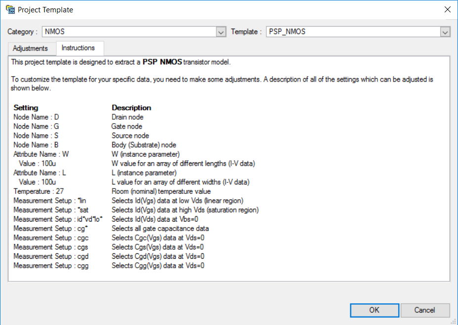
The user can now customize the selected project template, based on the data set. This is done by editing the values in the Data column. Instructions on how to do that and the meaning of fields and values can be found under the Instructions tab: opt_ex24_template_dialog_instructions.png .
Step 3: Customizing the template
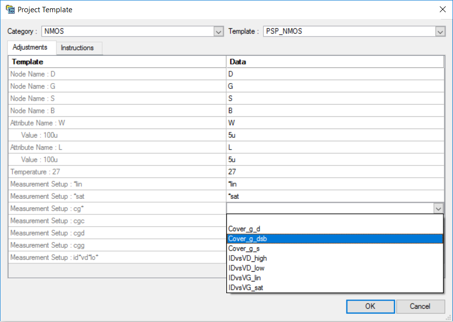
The default node assignment is straightforward in this case. Also, the dataset has the same attribute names (W and L) and the same room temperature value (27) as the template, so these settings do not need adjustments. The dataset includes an I-V data W array of devices with an L of 5um and a L array of devices with a W of 5um, so the default attribute values selected by Utmost IV are correct. The first two measurement setup names, "*lin" and "*sat", have been automatically assigned by Utmost IV. The next ones require adjustments. One can either choose the setup names from a pull-down list or edit the name in place: opt_ex24_template_dialog_pull_down.png .
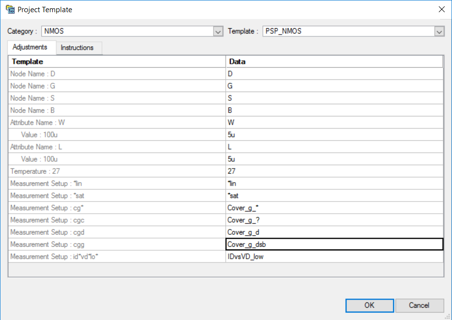
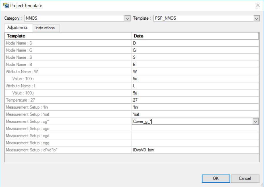
In the case of "cg*" mapping, the intention is to select all the Cg-related measurement setups. So instead of making a selection from the pull-down list, we will directly edit the name as "Cover_g_*". This will select all the Cg-related data in the dataset: opt_ex24_template_dialog_manual_editing.png .
Regarding "cgc" (the gate to channel capacitance), this particular data is missing from the loaded dataset. Instead, knowing that cgc = cgs + cgd, we can choose to use both cgs and cgd data available in the dataset (i.e., "Cover_g_s" and "Cover_g_d"), so we need to edit the name in the Data column to "Cover_g_?".
For the other two cg-related measurement setup names, the selection can be made from the pull-down list, with "cgd" being adjusted to "Cover_g_d" and "cgg" to "Cover_g_dsb".
The "id*vd*lo*" measurement setup in the PSP template is intended to select the Id(Vds) data at Vbs=0. In our data set, this is identified by the "IDvsVD_low" measurement setup name, which is selected correctly by default.
After all the adjustments are done, the Project Template dialog will look as shown in opt_ex24_template_dialog_final.png .
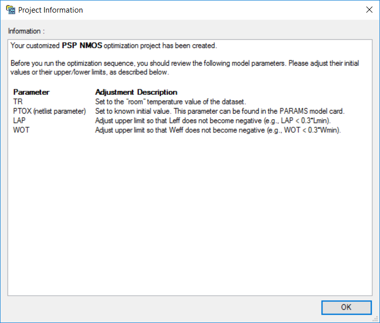
Clicking the "OK" button, will display an information dialog: opt_ex24_project_information.png .
This dialog contains instructions on further adjustments that may be needed in order to run the resulting optimization project. This information can be also retrieved later by selecting File->Project Information from the Utmost IV menu.
Step 4: Creating and running the optimization project
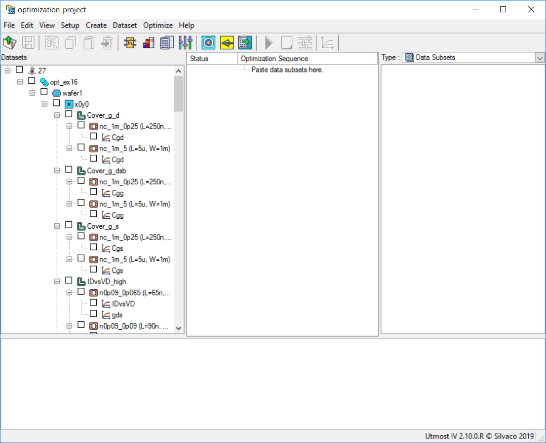
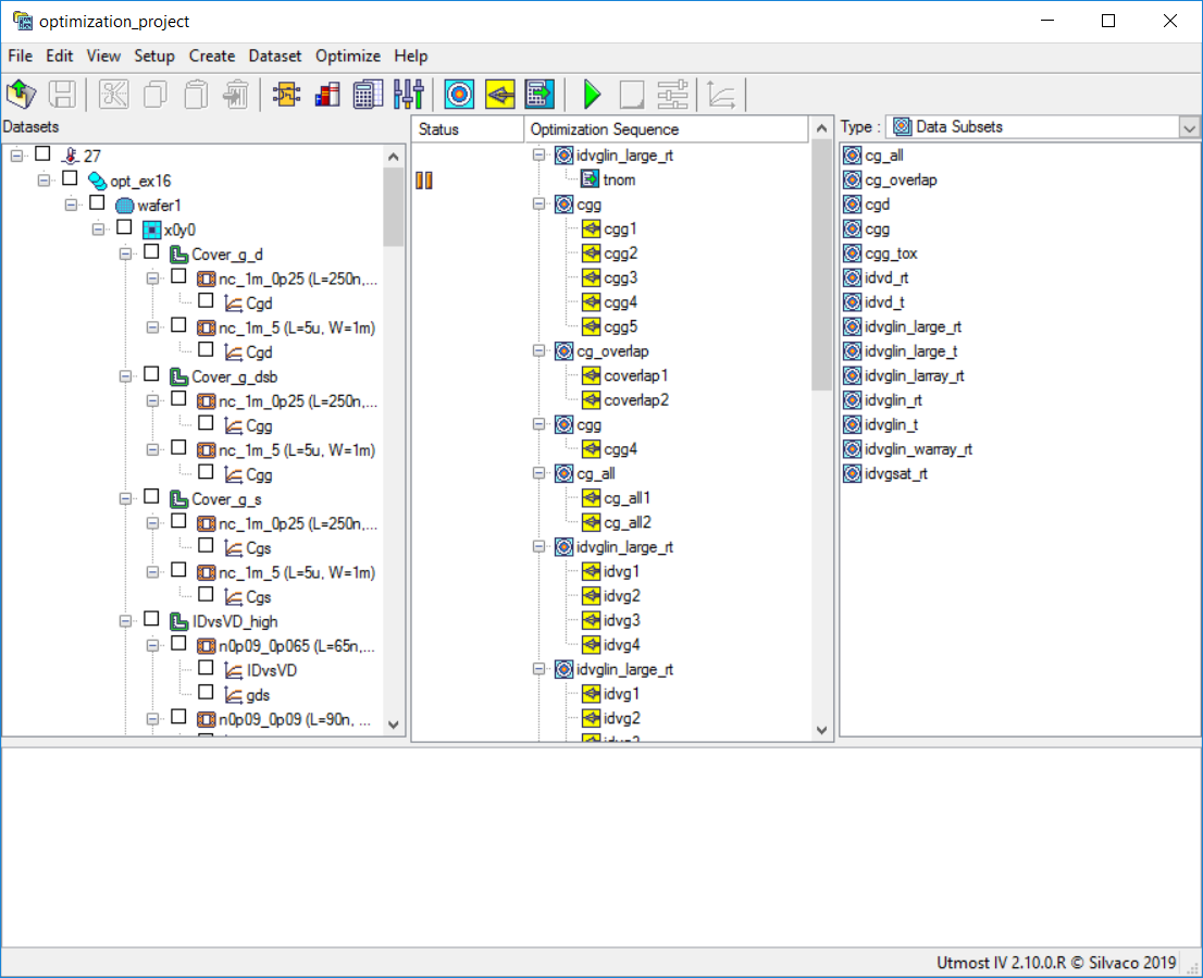
After clicking the "OK" button in the information dialog, the resulting optimization project will be created: opt_ex24_optimization_project.png .
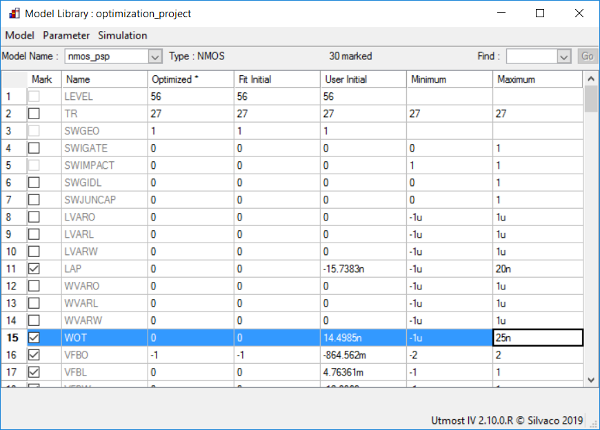
As mentioned in the Project Information dialog above, some of the model parameters initial values and limits may need to be revised. In order to do so, one can select Setup->Model Library from the Utmost IV menu. This will open the Model Library dialog, where the initial value of TR and the upper limits of the LAP and WOT model parameters may be adjusted, as shown in opt_ex24_model_parameter_adjustments.png .
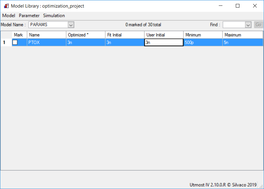
The initial value of the PTOX parameter can be updated in the Model Library dialog, under the special PARAMS model name: opt_ex24_PTOX_parameter_adjustment.png .
Before running the optimization project, it is time to save it by selecting File->Save As from the Utmost IV menu.
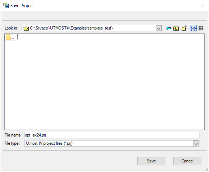
If running Utmost IV in file mode, enter "opt_ex24.prj" in the Save Project dialog, as shown in opt_ex24_save_project_dialog.png .
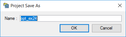
If running Utmost IV in database mode, enter "opt_ex24" in the Project Save As dialog, as shown in opt_ex24_save_project_dialog_database.png .
After saving it, the project will look as in the following figure: opt_ex24_project_saved.png .
Now the project can be run by selecting Optimize->Run/Continue from the Utmost IV menu or by pressing the green "Run" button.
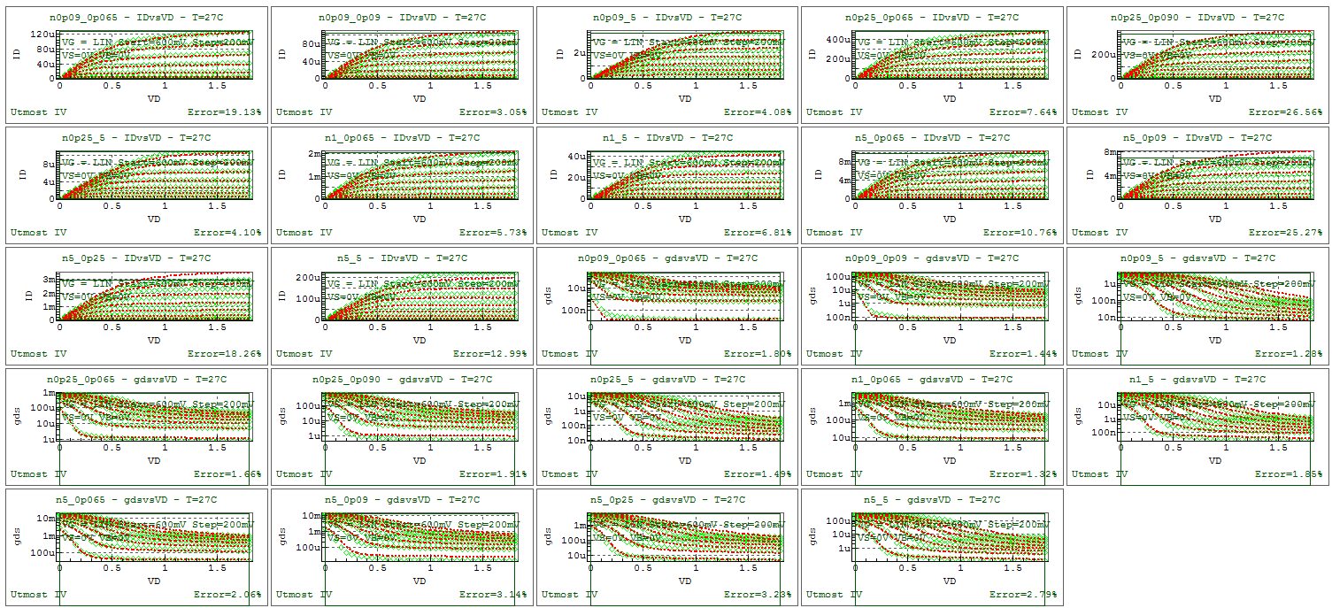
Running the optimization project can take a long time (typically, over one hour). After the process has completed, the fit to measured data will be as shown in opt_ex24_final_fit.png .
When complete, the model card and the netlist parameters can be exported into an external model library file as shown in the output file opt_ex24.lib.
opt_ex24.lib
											.PARAM PTOX     = 2.63167e-09
.MODEL nmos_psp NMOS (
+LEVEL    = 56             TR       = 27             SWGEO    = 1
+SWIGATE  = 0              SWIMPACT = 0              SWGIDL   = 0
+SWJUNCAP = 0              LVARO    = 0              LVARL    = 0
+LVARW    = 0              LAP      = -1.11859e-08   WVARO    = 0
+WVARL    = 0              WVARW    = 0              WOT      = 7.29506e-09
+VFBO     = -1.88479       VFBL     = 0.0105707      VFBW     = -0.010898
+VFBLW    = 0.00255883     STVFBO   = 0.0005         STVFBL   = 0
+STVFBW   = 0              STVFBLW  = 0              TOXO     = PTOX
+DPHIBO   = 0.543737       NSUBO    = 1.00036e+24    NSUBW    = 0
+WSEG     = 1e-08          NPCK     = 1e+23          NPCKW    = 0
+WSEGP    = 1e-08          LPCK     = 1e-08          LPCKW    = 0
+VNSUBO   = 0              NSLPO    = 0.05           DNSUBO   = 0
+NPO      = 0              NPL      = 0              QMC      = 1
+CTO      = 0.00205709     CTL      = -3.1198e-07    CTW      = 0
+CTLEXP   = 1.00031        TOXOVO   = PTOX           LOV      = 4.31624e-08
+NOVO     = 1.79893e+26    FOL1     = 0.0176491      FOL2     = 0
+CFL      = 4.09568e-05    CFLEXP   = 2              CFW      = 0
+CFBO     = 0              UO       = 0.0332836      FBET1    = -0.393881
+FBET1W   = -0.130639      LP1      = 1e-08          LP1W     = 0
+FBET2    = 0              LP2      = 1e-08          BETW1    = 0.0398438
+BETW2    = 0              WBET     = 1e-09          STBETO   = 1
+STBETL   = 0              STBETW   = 0              STBETLW  = 0
+MUEO     = 0.510407       MUEW     = 0.0388059      STMUEO   = 0
+THEMUO   = 2.19867        STTHEMUO = 1.5            CSO      = 0.404939
+CSW      = -1.15697       STCSO    = 0              XCORO    = 0
+XCORL    = 0              XCORW    = 0              XCORLW   = 0
+STXCORO  = 0              RSW1     = 61.3864        RSW2     = 0
+STRSO    = 1              RSBO     = 0.612699       RSGO     = 2.36073
+THESATO  = 0.396943       THESATL  = 0.0455138      THESATW  = 0
+STTHESATO = 0
+THESATBO = 0              THESATGO = 0              AXO      = 3.99726
+AXL      = 0.0470015      ALPL     = 0.0167512      ALPLEXP  = 1
+ALPW     = 0              ALP1L1   = 0.0136384      ALP1L2   = 0
+ALP1LEXP = 0              ALP1W    = 0              ALP2L1   = 0.00136711
+ALP2L2   = 0              ALP2W    = 0              VPO      = 1.44766
+A1O      = 1              A1W      = 0              A2O      = 10
+STA2O    = 0              A3O      = 0              A3L      = 0
+A3W      = 0              A4O      = 0              A4W      = 0
+GCOO     = 0              IGINVLW  = 0              IGOVW    = 0
+GC2O     = 0.375          GC3O     = 0.063          CHIBO    = 3.1
+STIGO    = 2              AGIDLW   = 0              BGIDLO   = 41
+STBGIDLO = 0              CGIDLO   = 0              CGBOVL   = 0
+CFRW     = 0              NFALW    = 8e+22          NFBLW    = 3e+07
+NFCLW    = 0              DTA      = 0              TRJ      = 21
+IMAX     = 1000           CJORBOT  = 0.001          CJORSTI  = 1e-09
+CJORGAT  = 1e-09          VBIRBOT  = 1              VBIRSTI  = 1
+VBIRGAT  = 1              PBOT     = 0.5            PSTI     = 0.5
+PGAT     = 0.5            PHIGBOT  = 1.16           PHIGSTI  = 1.16
+PHIGGAT  = 1.16
+IDSATRBOT = 1e-12
+IDSATRSTI = 1e-18
+IDSATRGAT = 1e-18
+XJUNSTI  = 1e-07          XJUNGAT  = 1e-07          CSRHBOT  = 100
+CSRHSTI  = 0.0001         CSRHGAT  = 0.0001         CTATBOT  = 100
+CTATSTI  = 0.0001         CTATGAT  = 0.0001
+MEFFTATBOT = 0.25
+MEFFTATSTI = 0.25
+MEFFTATGAT = 0.25
+CBBTBOT  = 1e-12          CBBTSTI  = 1e-18          CBBTGAT  = 1e-18
+FBBTRBOT = 1e+09          FBBTRSTI = 1e+09          FBBTRGAT = 1e+09
+STFBBTBOT = -0.001
+STFBBTSTI = -0.001
+STFBBTGAT = -0.001
+VBRBOT   = 10             VBRSTI   = 10             VBRGAT   = 10
+PBRBOT   = 4              PBRSTI   = 4              PBRGAT   = 4 )