opt_ex21 : RPI poly-Si TFT Model Extraction
Requires: Utmost IV, SmartSpice, SmartView
Minimum Versions: Utmost IV 2.4.0.R, SmartSpice 4.32.0.R, SmartView 2.34.0.R.
This example describes how to extract an RPI poly-Si TFT (L36) model. To extract a model which is scalable with geometry, multiple different device sizes must be included. In this example, five devices with different gate lengths are included.
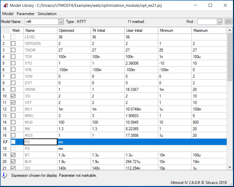
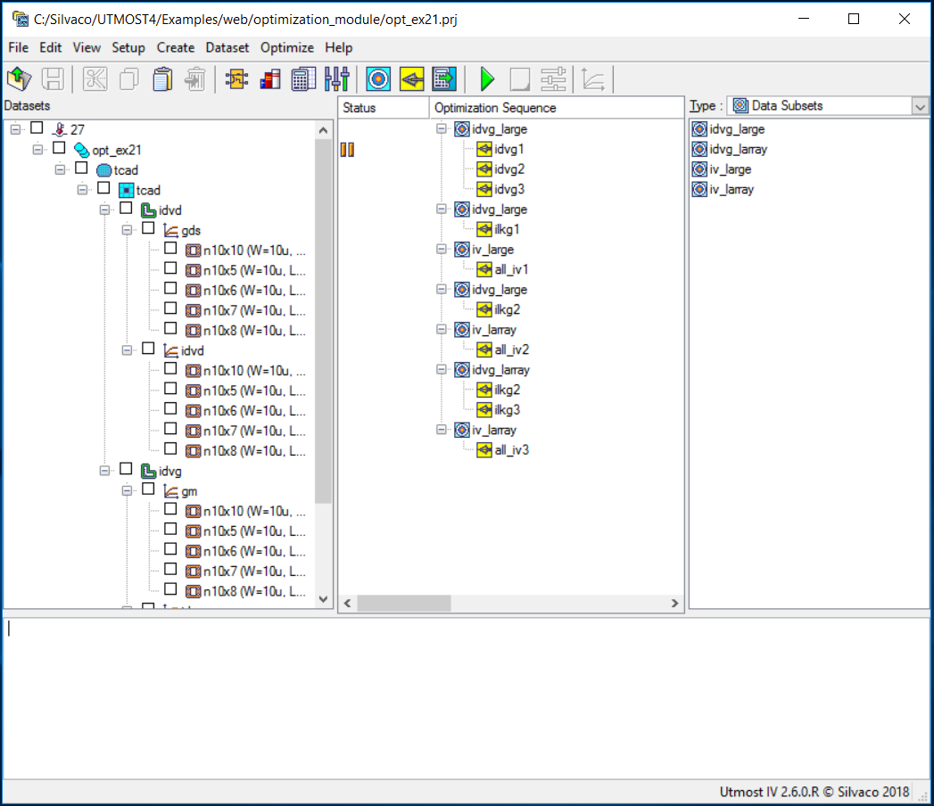
The project file opt_ex21.prj and the data file opt_ex21.uds for this example should be loaded into your database. When opened, the project will look as shown in opt_ex21_project.png .
The optimization sequence, which fully automates the extraction of this TFT model, has seven sections. The objective of each section is to isolate a device characteristic and then to optimize only those model parameters which account for this device behavior.
Preliminary information
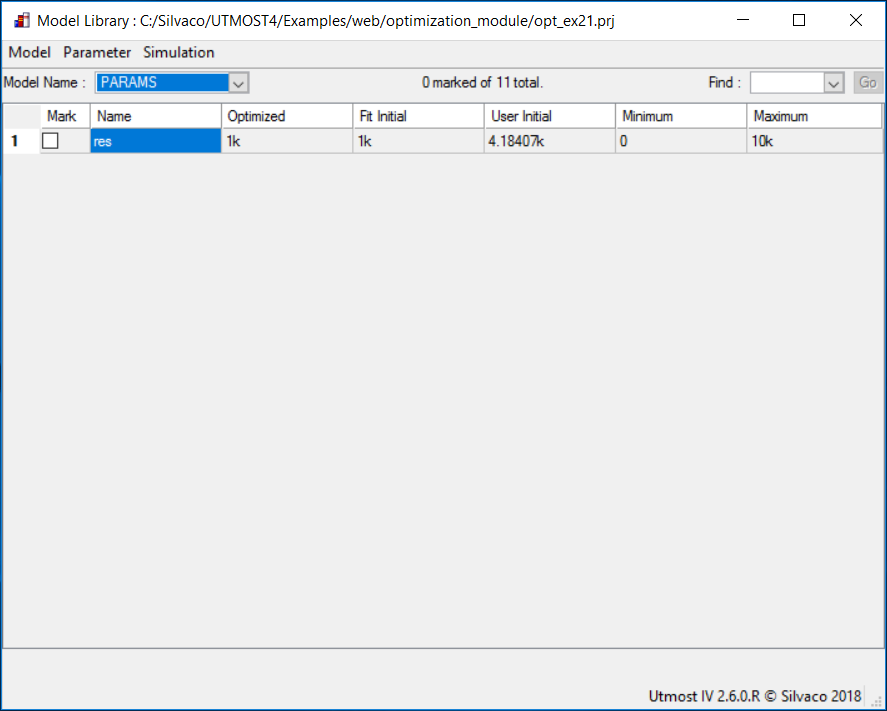
The RPI TFT model allows independent parameters to describe the source and drain region resistances. In order to consider symmetric devices, with the same parameter values for drain and source, respectively, one can assign two model parameters to the same netlist parameter and optimize the netlist parameter instead: opt_ex21_model_card.png and opt_ex21_netlist_parameters.png .
The optimization sequence, which automates the parameter extraction, is divided into seven sections. Some model parameters are optimized in multiple sections for better fitting.
Before starting the optimization sequence, the following device parameters are defined in the model library.
- TOX: Oxide thickness
- TNOM: Nominal (room) temperature
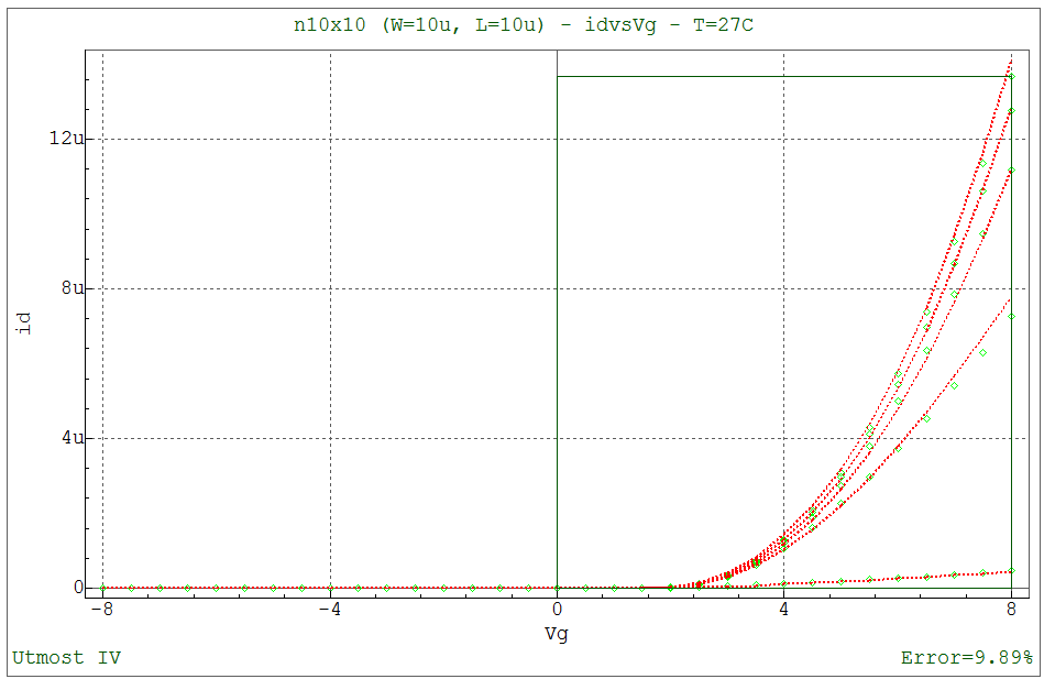
Section 1 : idvg_large
This section optimizes the parameters for wide and long channel devices. The data in this section is the drain current versus gate voltage characteristic. The following model parameters are extracted.
- VTO Zero-bias threshold voltage
- ETA Subthreshold ideality factor
- MU0 High-field mobility
- MU1 Low-field mobility parameter
- MMU Low-field mobility exponent
- MUS Subthreshold mobility
- MK Kink effect exponent
After this step has been completed, the fit to measured data will be as shown in opt_ex21_01.png .
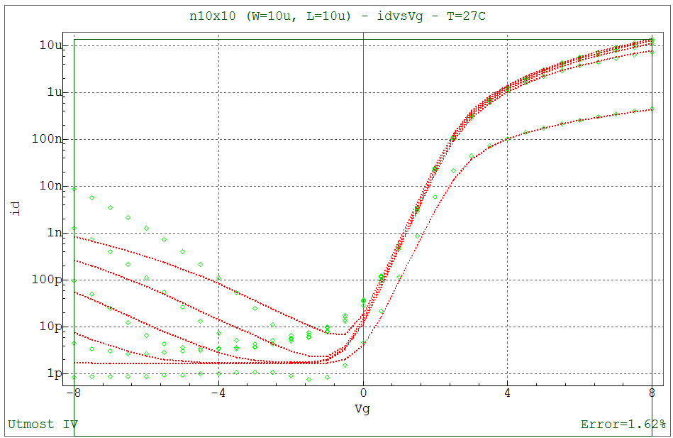
Section 2: idvg_large
This section extracts preliminary values of the following leakage current parameters.
- BLK Leakage barrier lowering constant
- DD Vds field constant
- DG Vgs field constant
- EB Barrier height of diode
After this step has been completed, the fit to measured data will be as shown in opt_ex21_02.png .
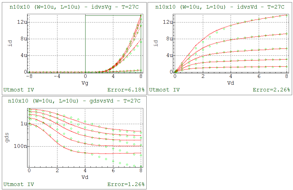
Section 3: iv_large
This section uses combined id-vgs and id-vds large geometry data to extract the model parameters responsible for the saturation region of the device. The following parameters are optimized.
- VTO Zero-bias threshold voltage
- MU0 High-field mobility
- MU1 Low-field mobility parameter
- MMU Low-field mobility exponent
- MUS Subthreshold mobility
- MK Kink effect exponent
- VKINK Kink effect voltage
- DELTA Transition width parameter
- ASAT Proportionality constant of Vdsat
- VMAX Saturation velocity
- LAMBDA Channel length modulation parameter
After this step has been completed, the fit to measured data will be as shown in opt_ex21_03.png .
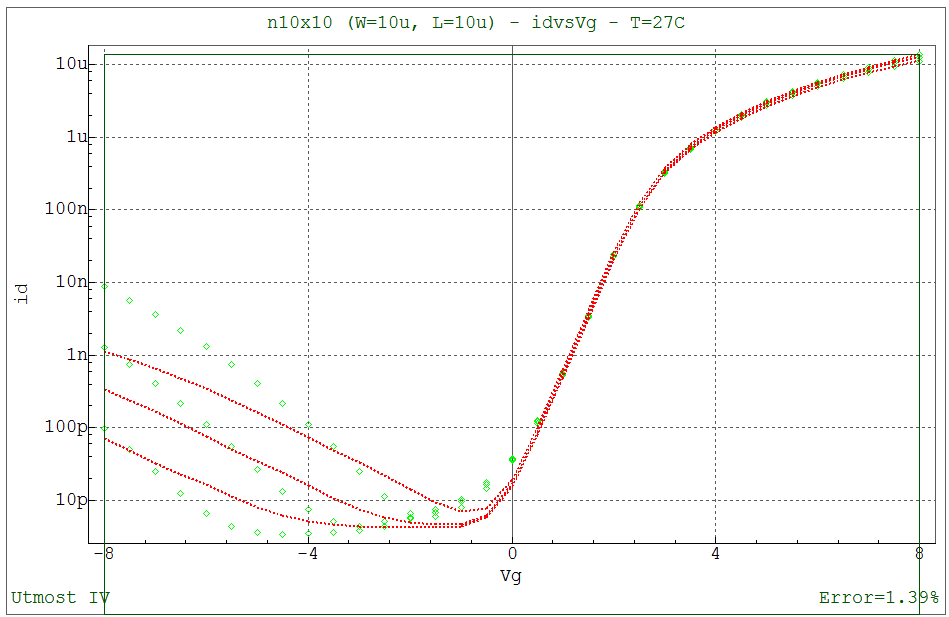
Section 4: idvg_large
This section refines the values of previously extracted leakage current parameters. The following parameters are optimized.
- BLK Leakage barrier lowering constant
- DD Vds field constant
- DG Vgs field constant
- EB Barrier height of diode
After this step has been completed, the fit to measured data will be as shown in opt_ex21_04.png .
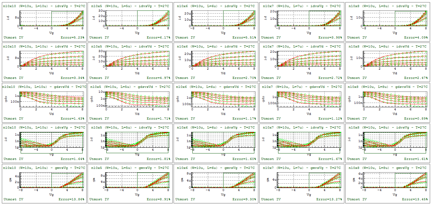
Section 5 : iv_larray
This section uses combined id-vgs and id-vds of devices with multiple gate lengths to optimize the following model parameters responsible for the saturation region.
- VTO Zero-bias threshold voltage
- MU0 High-field mobility
- MU1 Low-field mobility parameter
- MMU Low-field mobility exponent
- MUS Subthreshold mobility
- MK Kink effect exponent
- VKINK Kink effect voltage
- LKINK Kink effect constant
- DELTA Transition width parameter
- ASAT Proportionality constant of Vdsat
- VMAX Saturation velocity
- LAMBDA Channel length modulation parameter
- AT First DIBL parameter
After this step has been completed, the fit to measured data will be as shown in opt_ex21_05.png .
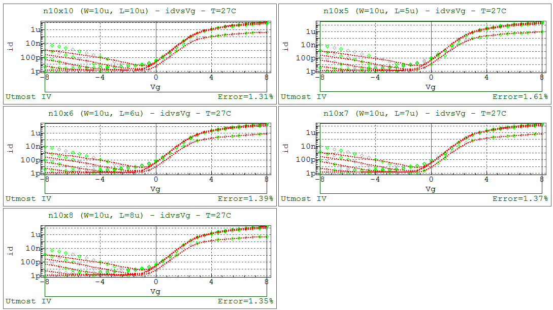
Section 6: idvg_larray
This section optimizes the leakage current parameters using subthreshold id-vgs data from devices with multiple channel lengths. The following parameters are optimized.
- ETA Subthreshold ideality factor
- BLK Leakage barrier lowering constant
- DD Vds field constant
- DG Vgs field constant
- EB Barrier height of diode
- I0 Leakage scaling constant
- I00 Reverse diode saturation constant
After this step has been completed, the fit to measured data will be as shown in opt_ex21_06.png .
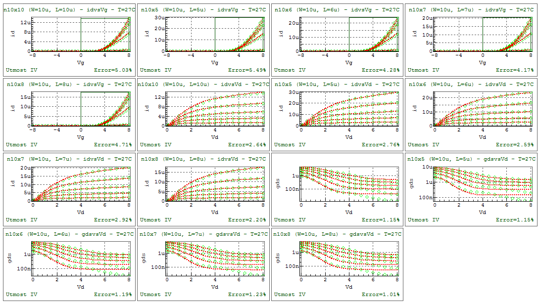
Section 7 : iv_larray
This section refines all previously extracted parameters using combined I-V data from devices of multiple gate lengths.
After this step has been completed, the fit to measured data will be as shown in opt_ex21_07.png .
When complete, the model card and the netlist parameters can be exported into an external model library file as shown in the output file opt_ex21.lib.
opt_ex21.lib
											.PARAM res      = 4184.07
.MODEL ntft NTFT (
+LEVEL    = 36             VERSION  = 2              TNOM     = 27
+TOX      = 1e-07          VTO      = 2.36006        VFB      = -0.1
+VON      = 0              DVT      = 0              VKINK    = 18.3367
+VSI      = 2              VST      = 2              MU1      = 0.0100748
+MMU      = 1.90003        MU0      = 10.0945        MK       = 8.22365
+MUS      = 17.3898        RD       = res            RS       = res
+BT       = 1.3e-06        BLK      = 0.000294721    DD       = 1.12294e-07
+DELTA    = 3.99279        DG       = 1.09486e-07    EB       = 0.507969
+ETA      = 10.6987        I0       = 9.82327        I00      = 84.9234
+ASAT     = 1.03641        AT       = 1.64967e-10    DASAT    = 0
+LASAT    = 0              LKINK    = 4.66355e-06    DVTO     = 0
+DMU1     = 0              CAPMOD   = 0              ETAC00   = 0
+MC       = 3              RDX      = 0              RSX      = 0
+ZEROC    = 0              ME       = 2.5            MSS      = 1.5
+VMAX     = 57247.9        THETA    = 0              ISUBMOD  = 0
+LAMBDA   = 0.0427131      INTDSNOD = 0              SCALERPI = 0 )
opt_ex21.uds
Utmost IV CSV Data Logfile Format Version 2 Copyright (c) 1984-2018 Silvaco, Inc. All rights reserved DataSetStart DataSetName, idvd MeasurementType, DC BatchName, opt_ex21 WaferName, tcad DieName, tcad DeviceName, n10x10 Temperature, 27 FabDate, 1 May 2018 UserDate, 1 May 2018 Attribute, W, 1e-05 Attribute, L, 1e-05 NodeNames, s g d Sweep, 1, V, d, LIST, 0.1, 0 List, 1 0.01 0.1 0.5 1 1.5 2 2.5 3 3.5 4 4.5 5 5.5 6 6.5 7 7.5 8 Sweep, 2, V, g, LIST, 0.1, 0 List, 2 4 5 6 7 8 Constant, V, s, 0, 0.1, 0 Target, I, d Target, I, s Function, gds, derivative (Vd, Id) Plot, idvd, XY (LIN LIN), vd, id Plot, gds, XY (LIN LOG), vd, gds DataArray, id 1.085061849e-08 1.054961535e-07 4.634413809e-07 7.794422867e-07 9.698541511e-07 1.064890388e-06 1.10965482e-06 1.141089799e-06 1.171834478e-06 1.200821756e-06 1.224764471e-06 1.24345496e-06 1.257919653e-06 1.269297199e-06 1.278655205e-06 1.286691311e-06 1.293795717e-06 1.300176249e-06 1.813863714e-08 1.778995465e-07 8.147160639e-07 1.453727013e-06 1.933383707e-06 2.269396273e-06 2.481859577e-06 2.602808207e-06 2.678286684e-06 2.744805539e-06 2.811773522e-06 2.873286948e-06 2.925623566e-06 2.968713526e-06 3.004017726e-06 3.032818239e-06 3.05622053e-06 3.075746125e-06 2.644406044e-08 2.605099759e-07 1.217911742e-06 2.2353834e-06 3.068006469e-06 3.729027087e-06 4.23186374e-06 4.592362678e-06 4.832590072e-06 4.987484834e-06 5.10604896e-06 5.222057001e-06 5.334868719e-06 5.437789131e-06 5.528045906e-06 5.605590218e-06 5.671787651e-06 5.728432886e-06 3.57085196e-08 3.527370731e-07 1.669760445e-06 3.115792517e-06 4.353365453e-06 5.395054553e-06 6.252900153e-06 6.939493432e-06 7.468935413e-06 7.858590791e-06 8.132700001e-06 8.33205366e-06 8.510576244e-06 8.685273583e-06 8.850626486e-06 9.002164828e-06 9.138192653e-06 9.258733703e-06 4.58659728e-08 4.539263425e-07 2.167119442e-06 4.088854529e-06 5.779988022e-06 7.252439915e-06 8.517502947e-06 9.586738333e-06 1.047234858e-05 1.118762809e-05 1.17477579e-05 1.217132879e-05 1.248752111e-05 1.275105741e-05 1.300046468e-05 1.323881318e-05 1.346234804e-05 1.366876963e-05 DataArray, is -1.085061475e-08 -1.054961692e-07 -4.634413216e-07 -7.794426176e-07 -9.698537541e-07 -1.064890639e-06 -1.109654578e-06 -1.141089799e-06 -1.171833884e-06 -1.200820535e-06 -1.224763138e-06 -1.243453725e-06 -1.257919507e-06 -1.269296953e-06 -1.278654395e-06 -1.28669437e-06 -1.293798955e-06 -1.300179463e-06 -1.813859118e-08 -1.778995625e-07 -8.147158432e-07 -1.453726948e-06 -1.933383809e-06 -2.269396212e-06 -2.481859823e-06 -2.602808081e-06 -2.67828641e-06 -2.744805961e-06 -2.811773823e-06 -2.873287488e-06 -2.925623655e-06 -2.96871357e-06 -3.004017614e-06 -3.032817285e-06 -3.056224497e-06 -3.075748901e-06 -2.644403093e-08 -2.605100075e-07 -1.217911577e-06 -2.235383514e-06 -3.06800673e-06 -3.729027129e-06 -4.231863254e-06 -4.592363178e-06 -4.832590393e-06 -4.987485003e-06 -5.106049747e-06 -5.222057606e-06 -5.33486935e-06 -5.437789076e-06 -5.52804465e-06 -5.605585866e-06 -5.67178734e-06 -5.728429632e-06 -3.570856804e-08 -3.527370546e-07 -1.669760443e-06 -3.115792697e-06 -4.353365881e-06 -5.395054319e-06 -6.252900825e-06 -6.939493627e-06 -7.468935798e-06 -7.858592162e-06 -8.132700519e-06 -8.332055909e-06 -8.510577295e-06 -8.685273975e-06 -8.850628045e-06 -9.002163258e-06 -9.138190118e-06 -9.258733546e-06 -4.586598994e-08 -4.539263201e-07 -2.167119161e-06 -4.088855015e-06 -5.779988228e-06 -7.252439033e-06 -8.517502489e-06 -9.586738042e-06 -1.047234697e-05 -1.118762661e-05 -1.174775777e-05 -1.217132773e-05 -1.248752028e-05 -1.275105771e-05 -1.300046343e-05 -1.323881269e-05 -1.346234734e-05 -1.366876829e-05 DataSetFinish DataSetStart DataSetName, idvd MeasurementType, DC BatchName, opt_ex21 WaferName, tcad DieName, tcad DeviceName, n10x5 Temperature, 27 FabDate, 1 May 2018 UserDate, 1 May 2018 Attribute, W, 1e-05 Attribute, L, 5e-06 NodeNames, s g d Sweep, 1, V, d, LIST, 0.1, 0 List, 1 0.01 0.1 0.5 1 1.5 2 2.5 3 3.5 4 4.5 5 5.5 6 6.5 7 7.5 8 Sweep, 2, V, g, LIST, 0.1, 0 List, 2 4 5 6 7 8 Constant, V, s, 0, 0.1, 0 Target, I, d Target, I, s Function, gds, derivative (Vd, Id) Plot, idvd, XY (LIN LIN), vd, id Plot, gds, XY (LIN LOG), vd, gds DataArray, id 2.213580112e-08 2.152989649e-07 9.479503143e-07 1.601881925e-06 2.009502129e-06 2.236083118e-06 2.373210477e-06 2.493738801e-06 2.618866803e-06 2.736725657e-06 2.8384989e-06 2.923188089e-06 2.993179845e-06 3.050696604e-06 3.097640686e-06 3.136850483e-06 3.170724901e-06 3.200754729e-06 3.679188008e-08 3.609181396e-07 1.654715113e-06 2.958747101e-06 3.947867056e-06 4.657866501e-06 5.134875374e-06 5.449507003e-06 5.701831249e-06 5.956296272e-06 6.206916744e-06 6.439193251e-06 6.646731411e-06 6.828441245e-06 6.986252672e-06 7.123574022e-06 7.242737379e-06 7.34379628e-06 5.346024233e-08 5.267226383e-07 2.464158225e-06 4.528169947e-06 6.225543468e-06 7.586030188e-06 8.64096607e-06 9.427459969e-06 9.996411742e-06 1.044261805e-05 1.08669669e-05 1.128417401e-05 1.168197141e-05 1.205218742e-05 1.239115995e-05 1.26980726e-05 1.297403941e-05 1.322162609e-05 7.202742455e-08 7.115671264e-07 3.369946374e-06 6.293306141e-06 8.802491768e-06 1.092521908e-05 1.268904522e-05 1.412338546e-05 1.526053795e-05 1.614117468e-05 1.68494971e-05 1.749445885e-05 1.811438491e-05 1.870816853e-05 1.927049959e-05 1.979793666e-05 2.028886666e-05 2.074303564e-05 9.236254819e-08 9.141553182e-07 4.365852664e-06 8.242012078e-06 1.165962127e-05 1.464465911e-05 1.7222557e-05 1.941988269e-05 2.126454461e-05 2.278571046e-05 2.402163336e-05 2.505158339e-05 2.597320433e-05 2.683819775e-05 2.766117902e-05 2.844426898e-05 2.918697161e-05 2.988877108e-05 DataArray, is -2.213576851e-08 -2.152990021e-07 -9.479502612e-07 -1.601882365e-06 -2.009502502e-06 -2.236082644e-06 -2.373210225e-06 -2.493738594e-06 -2.61886603e-06 -2.736724677e-06 -2.838498948e-06 -2.92318874e-06 -2.993179426e-06 -3.050696555e-06 -3.097640313e-06 -3.136851488e-06 -3.170724917e-06 -3.200755849e-06 -3.679185364e-08 -3.609180515e-07 -1.654715148e-06 -2.958747002e-06 -3.947866678e-06 -4.657866634e-06 -5.134876287e-06 -5.44950685e-06 -5.701831432e-06 -5.956296773e-06 -6.206916055e-06 -6.439194622e-06 -6.646731318e-06 -6.82844109e-06 -6.986252646e-06 -7.123570546e-06 -7.242735466e-06 -7.343794163e-06 -5.346025207e-08 -5.267225927e-07 -2.464158336e-06 -4.528170325e-06 -6.225543021e-06 -7.586030565e-06 -8.64096516e-06 -9.427459827e-06 -9.996412121e-06 -1.044261991e-05 -1.08669683e-05 -1.128417543e-05 -1.168197206e-05 -1.205218873e-05 -1.239115969e-05 -1.269806993e-05 -1.297403783e-05 -1.322162518e-05 -7.202742123e-08 -7.115671243e-07 -3.369946372e-06 -6.293305802e-06 -8.802492106e-06 -1.092521914e-05 -1.268904573e-05 -1.412338541e-05 -1.526053607e-05 -1.614117479e-05 -1.684949584e-05 -1.749445844e-05 -1.811438403e-05 -1.870816792e-05 -1.927049938e-05 -1.979793384e-05 -2.028886814e-05 -2.074303496e-05 -9.236251309e-08 -9.141552646e-07 -4.365852647e-06 -8.242011933e-06 -1.16596215e-05 -1.464465964e-05 -1.722255705e-05 -1.941988259e-05 -2.126454409e-05 -2.278571124e-05 -2.402163333e-05 -2.505158417e-05 -2.597320473e-05 -2.683819957e-05 -2.766118042e-05 -2.844426849e-05 -2.918697154e-05 -2.988877068e-05 DataSetFinish DataSetStart DataSetName, idvd MeasurementType, DC BatchName, opt_ex21 WaferName, tcad DieName, tcad DeviceName, n10x6 Temperature, 27 FabDate, 1 May 2018 UserDate, 1 May 2018 Attribute, W, 1e-05 Attribute, L, 6e-06 NodeNames, s g d Sweep, 1, V, d, LIST, 0.1, 0 List, 1 0.01 0.1 0.5 1 1.5 2 2.5 3 3.5 4 4.5 5 5.5 6 6.5 7 7.5 8 Sweep, 2, V, g, LIST, 0.1, 0 List, 2 4 5 6 7 8 Constant, V, s, 0, 0.1, 0 Target, I, d Target, I, s Function, gds, derivative (Vd, Id) Plot, idvd, XY (LIN LIN), vd, id Plot, gds, XY (LIN LOG), vd, gds DataArray, id 1.831014552e-08 1.780617935e-07 7.832360276e-07 1.320861653e-06 1.651392416e-06 1.827908216e-06 1.926360288e-06 2.006875487e-06 2.088782587e-06 2.164775193e-06 2.228590475e-06 2.280231168e-06 2.321884484e-06 2.35523327e-06 2.382035162e-06 2.404306131e-06 2.42346554e-06 2.440356258e-06 3.049987863e-08 2.991709285e-07 1.370961159e-06 2.449125974e-06 3.263277261e-06 3.841911682e-06 4.221848146e-06 4.460121411e-06 4.636131033e-06 4.80829644e-06 4.977371317e-06 5.131338274e-06 5.265216276e-06 5.379027075e-06 5.475288148e-06 5.557123224e-06 5.625960258e-06 5.682769674e-06 4.437299447e-08 4.371668978e-07 2.044585361e-06 3.75514961e-06 5.158805964e-06 6.279288357e-06 7.141355128e-06 7.774540998e-06 8.219133652e-06 8.543381169e-06 8.837289446e-06 9.126015296e-06 9.399154606e-06 9.648976323e-06 9.872512401e-06 1.006976357e-05 1.024258528e-05 1.039403882e-05 5.983397433e-08 5.910846364e-07 2.798769665e-06 5.224771754e-06 7.304343688e-06 9.059722168e-06 1.051275342e-05 1.168673857e-05 1.260772625e-05 1.330696185e-05 1.383809192e-05 1.429635547e-05 1.473320434e-05 1.514965733e-05 1.553973796e-05 1.589986023e-05 1.622867566e-05 1.652638858e-05 7.677335405e-08 7.598401345e-07 3.628308843e-06 6.847859862e-06 9.684024577e-06 1.215772402e-05 1.428920085e-05 1.609953459e-05 1.761112457e-05 1.88478583e-05 1.983656966e-05 2.062405053e-05 2.12963783e-05 2.191683285e-05 2.250308418e-05 2.305617074e-05 2.35746921e-05 2.405773716e-05 DataArray, is -1.831018874e-08 -1.780618006e-07 -7.832359459e-07 -1.320861468e-06 -1.651392048e-06 -1.827908277e-06 -1.92636029e-06 -2.006875031e-06 -2.088782358e-06 -2.164774261e-06 -2.228589256e-06 -2.280230717e-06 -2.321883784e-06 -2.355232298e-06 -2.382034467e-06 -2.404307229e-06 -2.423468959e-06 -2.440354165e-06 -3.04999047e-08 -2.99170893e-07 -1.370961355e-06 -2.449126176e-06 -3.263277098e-06 -3.841912328e-06 -4.221848893e-06 -4.460121274e-06 -4.63613088e-06 -4.808297003e-06 -4.977372214e-06 -5.131338708e-06 -5.265216626e-06 -5.379027209e-06 -5.475288563e-06 -5.557122307e-06 -5.625958818e-06 -5.682770623e-06 -4.437300458e-08 -4.371668741e-07 -2.044585183e-06 -3.755149608e-06 -5.15880545e-06 -6.279289141e-06 -7.141354658e-06 -7.774540464e-06 -8.219134724e-06 -8.543380715e-06 -8.837290135e-06 -9.126014653e-06 -9.399156045e-06 -9.64897639e-06 -9.872513867e-06 -1.006976291e-05 -1.024258469e-05 -1.039403741e-05 -5.983397798e-08 -5.910846434e-07 -2.798769758e-06 -5.224771411e-06 -7.304343724e-06 -9.059722097e-06 -1.051275377e-05 -1.168673885e-05 -1.260772436e-05 -1.330696201e-05 -1.383809084e-05 -1.429635516e-05 -1.473320435e-05 -1.514965658e-05 -1.553973592e-05 -1.58998586e-05 -1.622867611e-05 -1.652638681e-05 -7.677331239e-08 -7.598401744e-07 -3.628309107e-06 -6.847859945e-06 -9.684024368e-06 -1.215772384e-05 -1.428920076e-05 -1.609953453e-05 -1.761112423e-05 -1.884785774e-05 -1.983657042e-05 -2.062405024e-05 -2.129637918e-05 -2.191683312e-05 -2.250308354e-05 -2.305617184e-05 -2.357469275e-05 -2.405773653e-05 DataSetFinish DataSetStart DataSetName, idvd MeasurementType, DC BatchName, opt_ex21 WaferName, tcad DieName, tcad DeviceName, n10x7 Temperature, 27 FabDate, 1 May 2018 UserDate, 1 May 2018 Attribute, W, 1e-05 Attribute, L, 7e-06 NodeNames, s g d Sweep, 1, V, d, LIST, 0.1, 0 List, 1 0.01 0.1 0.5 1 1.5 2 2.5 3 3.5 4 4.5 5 5.5 6 6.5 7 7.5 8 Sweep, 2, V, g, LIST, 0.1, 0 List, 2 4 5 6 7 8 Constant, V, s, 0, 0.1, 0 Target, I, d Target, I, s Function, gds, derivative (Vd, Id) Plot, idvd, XY (LIN LIN), vd, id Plot, gds, XY (LIN LOG), vd, gds DataArray, id 1.564601885e-08 1.52146031e-07 6.691230706e-07 1.128089468e-06 1.409388805e-06 1.557629672e-06 1.637748843e-06 1.70201143e-06 1.768409205e-06 1.831313876e-06 1.884313874e-06 1.92680051e-06 1.960324066e-06 1.986363775e-06 2.006953454e-06 2.02396072e-06 2.0385421e-06 2.051332161e-06 2.608313807e-08 2.558405164e-07 1.172310881e-06 2.094099756e-06 2.789719262e-06 3.282972042e-06 3.604584937e-06 3.802579454e-06 3.944087006e-06 4.082230936e-06 4.221346379e-06 4.349571897e-06 4.461186638e-06 4.555551638e-06 4.634657486e-06 4.700775281e-06 4.754555344e-06 4.797902884e-06 3.796641478e-08 3.740415173e-07 1.749287146e-06 3.212763711e-06 4.413462382e-06 5.37126885e-06 6.106846336e-06 6.644917162e-06 7.019297199e-06 7.284476195e-06 7.519264046e-06 7.754890326e-06 7.981380195e-06 8.189851118e-06 8.376455616e-06 8.540536676e-06 8.683488035e-06 8.808045576e-06 5.121346274e-08 5.059183282e-07 2.395457305e-06 4.471919214e-06 6.251824421e-06 7.753853472e-06 8.996305686e-06 9.998718208e-06 1.078310679e-05 1.137587145e-05 1.181682096e-05 1.218510558e-05 1.253979242e-05 1.288326506e-05 1.320778235e-05 1.350843957e-05 1.378297652e-05 1.403097434e-05 6.573047385e-08 6.505406068e-07 3.10635264e-06 5.862877602e-06 8.291232267e-06 1.040901574e-05 1.22332237e-05 1.378157046e-05 1.507298097e-05 1.612792276e-05 1.696892e-05 1.762811241e-05 1.81748053e-05 1.86788691e-05 1.916059083e-05 1.961904234e-05 2.005099751e-05 2.045422863e-05 DataArray, is -1.564598046e-08 -1.521460076e-07 -6.69122797e-07 -1.128089518e-06 -1.409388527e-06 -1.55762936e-06 -1.637747787e-06 -1.702010941e-06 -1.768410713e-06 -1.831314934e-06 -1.884314176e-06 -1.926800656e-06 -1.960325005e-06 -1.986364777e-06 -2.006953826e-06 -2.023961195e-06 -2.038540971e-06 -2.05133218e-06 -2.608311835e-08 -2.558404936e-07 -1.172310821e-06 -2.094099812e-06 -2.789719586e-06 -3.282971824e-06 -3.604585099e-06 -3.802579644e-06 -3.944085877e-06 -4.082230899e-06 -4.221345775e-06 -4.349570943e-06 -4.461186584e-06 -4.555551881e-06 -4.63465757e-06 -4.700775346e-06 -4.754555472e-06 -4.797902239e-06 -3.796635572e-08 -3.740415594e-07 -1.749287168e-06 -3.212763894e-06 -4.413462854e-06 -5.371269062e-06 -6.106846282e-06 -6.644917234e-06 -7.019297435e-06 -7.284474594e-06 -7.519263133e-06 -7.754889783e-06 -7.981379151e-06 -8.189850439e-06 -8.3764543e-06 -8.540535976e-06 -8.683491076e-06 -8.808044177e-06 -5.121344028e-08 -5.059183025e-07 -2.395457068e-06 -4.471919324e-06 -6.251824677e-06 -7.753852674e-06 -8.99630508e-06 -9.998717496e-06 -1.078310763e-05 -1.137587237e-05 -1.181682163e-05 -1.218510564e-05 -1.253979338e-05 -1.288326663e-05 -1.32077829e-05 -1.350843874e-05 -1.378297858e-05 -1.403097431e-05 -6.573045071e-08 -6.505405371e-07 -3.10635257e-06 -5.862877604e-06 -8.291232404e-06 -1.040901575e-05 -1.223322377e-05 -1.378157059e-05 -1.507298187e-05 -1.612792296e-05 -1.696892199e-05 -1.762811358e-05 -1.817480735e-05 -1.867887019e-05 -1.916059065e-05 -1.961904529e-05 -2.00509988e-05 -2.045423059e-05 DataSetFinish DataSetStart DataSetName, idvd MeasurementType, DC BatchName, opt_ex21 WaferName, tcad DieName, tcad DeviceName, n10x8 Temperature, 27 FabDate, 1 May 2018 UserDate, 1 May 2018 Attribute, W, 1e-05 Attribute, L, 8e-06 NodeNames, s g d Sweep, 1, V, d, LIST, 0.1, 0 List, 1 0.01 0.1 0.5 1 1.5 2 2.5 3 3.5 4 4.5 5 5.5 6 6.5 7 7.5 8 Sweep, 2, V, g, LIST, 0.1, 0 List, 2 4 5 6 7 8 Constant, V, s, 0, 0.1, 0 Target, I, d Target, I, s Function, gds, derivative (Vd, Id) Plot, idvd, XY (LIN LIN), vd, id Plot, gds, XY (LIN LOG), vd, gds DataArray, id 1.363340071e-08 1.325655803e-07 5.827169422e-07 9.813204648e-07 1.223787803e-06 1.34864058e-06 1.412453577e-06 1.460845836e-06 1.509517799e-06 1.555486824e-06 1.594015623e-06 1.624753476e-06 1.649067849e-06 1.668369432e-06 1.684185118e-06 1.697697068e-06 1.709599108e-06 1.720274135e-06 2.275665401e-08 2.232040596e-07 1.022506055e-06 1.825538054e-06 2.430020628e-06 2.856297791e-06 3.130498027e-06 3.293819013e-06 3.404085202e-06 3.507035688e-06 3.610555394e-06 3.705939284e-06 3.788599098e-06 3.858258799e-06 3.916642242e-06 3.965505287e-06 4.005824829e-06 4.039371917e-06 3.314806817e-08 3.265649501e-07 1.52701139e-06 2.80363154e-06 3.849703379e-06 4.682277094e-06 5.318862318e-06 5.780297973e-06 6.09541452e-06 6.309651552e-06 6.487889837e-06 6.665112294e-06 6.836071606e-06 6.993185778e-06 7.133379205e-06 7.256411299e-06 7.363647322e-06 7.45725993e-06 4.473527643e-08 4.419159092e-07 2.092181218e-06 3.904885034e-06 5.45747867e-06 6.766043913e-06 7.846168632e-06 8.714328886e-06 9.38911198e-06 9.893204591e-06 1.025868844e-05 1.05455528e-05 1.081514237e-05 1.107693617e-05 1.13244193e-05 1.155329835e-05 1.176187846e-05 1.195009353e-05 5.743579974e-08 5.684412184e-07 2.714096049e-06 5.121682178e-06 7.241467917e-06 9.088647975e-06 1.067774991e-05 1.202378634e-05 1.314273971e-05 1.405205472e-05 1.477135791e-05 1.53253373e-05 1.576217246e-05 1.615118922e-05 1.652166228e-05 1.687436507e-05 1.720634915e-05 1.751579524e-05 DataArray, is -1.363340916e-08 -1.325655824e-07 -5.827169571e-07 -9.813201995e-07 -1.223787516e-06 -1.348639691e-06 -1.412453755e-06 -1.460845336e-06 -1.509516586e-06 -1.555486308e-06 -1.594015459e-06 -1.624753138e-06 -1.649067178e-06 -1.668367759e-06 -1.68418395e-06 -1.697698344e-06 -1.709600467e-06 -1.720275402e-06 -2.275662068e-08 -2.232040734e-07 -1.022506056e-06 -1.825538057e-06 -2.430020421e-06 -2.85629778e-06 -3.130497928e-06 -3.293818676e-06 -3.404084952e-06 -3.507035533e-06 -3.610555527e-06 -3.705937507e-06 -3.788598764e-06 -3.85825877e-06 -3.916641209e-06 -3.965505323e-06 -4.005823749e-06 -4.039372128e-06 -3.314805819e-08 -3.265649111e-07 -1.52701137e-06 -2.803631649e-06 -3.849703778e-06 -4.682277703e-06 -5.318862317e-06 -5.780298557e-06 -6.095414287e-06 -6.309652021e-06 -6.487889512e-06 -6.665112326e-06 -6.836072145e-06 -6.99318647e-06 -7.13337906e-06 -7.256410278e-06 -7.363650014e-06 -7.45726011e-06 -4.47352724e-08 -4.419159352e-07 -2.092181118e-06 -3.904885167e-06 -5.457478556e-06 -6.766044978e-06 -7.84616837e-06 -8.714328442e-06 -9.389112152e-06 -9.893204626e-06 -1.025868897e-05 -1.054555375e-05 -1.081514236e-05 -1.107693654e-05 -1.132441967e-05 -1.15532997e-05 -1.176188133e-05 -1.195009558e-05 -5.743580477e-08 -5.684411613e-07 -2.714096031e-06 -5.121682001e-06 -7.241467978e-06 -9.088647227e-06 -1.067774957e-05 -1.20237863e-05 -1.314273832e-05 -1.405205366e-05 -1.477135621e-05 -1.532533669e-05 -1.576217105e-05 -1.615118896e-05 -1.652166156e-05 -1.687436779e-05 -1.720635157e-05 -1.751579796e-05 DataSetFinish DataSetStart DataSetName, idvg MeasurementType, DC BatchName, opt_ex21 WaferName, tcad DieName, tcad DeviceName, n10x10 Temperature, 27 FabDate, 1 May 2018 UserDate, 1 May 2018 Attribute, W, 1e-05 Attribute, L, 1e-05 NodeNames, s g d Sweep, 1, V, g, LIST, 0.1, 0 List, 1 -8 -7.5 -7 -6.5 -6 -5.5 -5 -4.5 -4 -3.5 -3 -2.5 -2 -1.5 -1 -0.5 1.285828941e-15 0.5 1 1.5 2 2.5 3 3.5 4 4.5 5 5.5 6 6.5 7 7.5 8 Sweep, 2, V, d, LIST, 0.1, 0 List, 2 0.1 2 4 6 8 Constant, V, s, 0, 0.1, 0 Target, I, d Target, I, s Function, gm, derivative (Vg, Id) Plot, idvg, XY (LIN LIN), vg, id Plot, gm, XY (LIN LIN), vg, gm DataArray, id 8.36131195e-13 8.728686744e-13 8.893630423e-13 8.685134376e-13 8.832003358e-13 9.364460205e-13 9.378489438e-13 1.015002938e-12 1.019608944e-12 1.078242574e-12 1.098038583e-12 1.069092961e-12 9.15541197e-13 7.672785597e-13 8.375892066e-13 1.541404121e-12 4.662465554e-12 2.148801379e-11 1.165820216e-10 8.603206399e-10 5.99028876e-09 2.131315768e-08 4.492970488e-08 7.349079796e-08 1.054961856e-07 1.403743089e-07 1.778995483e-07 2.179677567e-07 2.605100179e-07 3.054587565e-07 3.527370753e-07 4.022575414e-07 4.539263276e-07 4.471557677e-12 3.412185968e-12 3.034900768e-12 2.713178615e-12 2.716666015e-12 2.868076125e-12 3.13780422e-12 3.147825586e-12 3.371339191e-12 3.443439032e-12 3.711232249e-12 4.367302474e-12 4.986971231e-12 6.252435859e-12 8.269363623e-12 1.342570439e-11 2.909022518e-11 9.846600144e-11 4.684946003e-10 2.994873201e-09 2.125970455e-08 1.000124964e-07 2.884760093e-07 6.099591415e-07 1.064890445e-06 1.628200004e-06 2.269396331e-06 2.971996647e-06 3.729027154e-06 4.537332549e-06 5.395053749e-06 6.300626558e-06 7.252438512e-06 9.675973144e-11 4.989852961e-11 2.462901509e-11 1.262024144e-11 6.689325654e-12 4.309420759e-12 3.657065076e-12 3.399083315e-12 3.528423262e-12 3.625605758e-12 3.836857393e-12 4.343799103e-12 5.615164181e-12 6.770704083e-12 9.593496344e-12 1.629601525e-11 3.5373417e-11 1.140539578e-10 5.201079761e-10 3.272555772e-09 2.31596388e-08 1.091619585e-07 3.172574926e-07 6.777862417e-07 1.200821738e-06 1.888469383e-06 2.744805569e-06 3.777330436e-06 4.987484845e-06 6.357337271e-06 7.858590781e-06 9.471981031e-06 1.118762806e-05 1.290581211e-09 7.415663611e-10 4.106907144e-10 2.18186126e-10 1.111413639e-10 5.490530377e-11 2.668117885e-11 1.343832261e-11 7.410562299e-12 5.149231772e-12 4.407316269e-12 5.194109522e-12 5.853619892e-12 7.582946289e-12 1.023673361e-11 1.762912932e-11 3.792755409e-11 1.21767233e-10 5.47178295e-10 3.408577968e-09 2.406014139e-08 1.131130528e-07 3.290991848e-07 7.079755251e-07 1.269297923e-06 2.022400356e-06 2.968713594e-06 4.107416443e-06 5.437789072e-06 6.962039809e-06 8.685273852e-06 1.061355916e-05 1.275105744e-05 8.816794063e-09 5.689816883e-09 3.578340105e-09 2.188970884e-09 1.296878048e-09 7.433822313e-10 4.101236472e-10 2.1751948e-10 1.109637506e-10 5.445302973e-11 2.489321713e-11 1.12674653e-11 6.587576053e-12 5.932758238e-12 7.894157287e-12 1.44527449e-11 3.693666963e-11 1.250849748e-10 5.619747838e-10 3.487090558e-09 2.45939667e-08 1.156375734e-07 3.363261601e-07 7.237998809e-07 1.300175321e-06 2.080544918e-06 3.075746503e-06 4.291882029e-06 5.728433271e-06 7.38385622e-06 9.258733767e-06 1.135305422e-05 1.366876963e-05 DataArray, is -8.002999308e-13 -7.867479554e-13 -8.342669403e-13 -8.353689667e-13 -8.265950502e-13 -8.98085787e-13 -9.049000233e-13 -9.420639799e-13 -9.906335581e-13 -1.04673117e-12 -1.068782926e-12 -1.036033603e-12 -8.815577396e-13 -6.975574358e-13 -7.86750044e-13 -1.458749133e-12 -4.599417029e-12 -2.142688252e-11 -1.165254238e-10 -8.603375314e-10 -5.990260831e-09 -2.131317125e-08 -4.492971552e-08 -7.349081055e-08 -1.054961842e-07 -1.403743732e-07 -1.778995835e-07 -2.179677478e-07 -2.605100194e-07 -3.054587924e-07 -3.527370438e-07 -4.022575589e-07 -4.539263136e-07 -3.879277319e-12 -2.786886328e-12 -2.320387111e-12 -2.214073799e-12 -2.21170892e-12 -2.27422053e-12 -2.354166925e-12 -2.500499906e-12 -2.693659483e-12 -2.875593063e-12 -3.146982422e-12 -3.691201267e-12 -4.554793964e-12 -5.743660442e-12 -7.857207287e-12 -1.292674317e-11 -2.858991704e-11 -9.793754815e-11 -4.674723381e-10 -2.994197415e-09 -2.125896075e-08 -1.000118736e-07 -2.884754638e-07 -6.099590282e-07 -1.064890644e-06 -1.628199733e-06 -2.269396204e-06 -2.971997231e-06 -3.72902718e-06 -4.537333335e-06 -5.395054259e-06 -6.300627413e-06 -7.252439076e-06 -9.64231617e-11 -4.977641315e-11 -2.458173186e-11 -1.198553946e-11 -6.242490991e-12 -3.906268222e-12 -3.077483217e-12 -2.904775748e-12 -2.971627843e-12 -3.137629687e-12 -3.480814987e-12 -4.092614346e-12 -5.048726096e-12 -6.525455936e-12 -9.157010574e-12 -1.565897619e-11 -3.486789636e-11 -1.139407313e-10 -5.204160215e-10 -3.271900108e-09 -2.315935966e-08 -1.091619862e-07 -3.172578964e-07 -6.777864978e-07 -1.200820503e-06 -1.888468453e-06 -2.744805966e-06 -3.777330622e-06 -4.987484998e-06 -6.357339046e-06 -7.858592175e-06 -9.471981437e-06 -1.118762661e-05 -1.288809649e-09 -7.419236026e-10 -4.1030545e-10 -2.179566319e-10 -1.110806277e-10 -5.44665898e-11 -2.601519287e-11 -1.265290095e-11 -6.815007453e-12 -4.600097931e-12 -4.091400838e-12 -4.422972434e-12 -5.33834445e-12 -6.884793587e-12 -9.695447501e-12 -1.677737564e-11 -3.766278224e-11 -1.217234065e-10 -5.468915479e-10 -3.408179195e-09 -2.405904985e-08 -1.131130907e-07 -3.290997263e-07 -7.079749113e-07 -1.269296927e-06 -2.022400554e-06 -2.968713564e-06 -4.107415744e-06 -5.437789034e-06 -6.962040467e-06 -8.685273966e-06 -1.061355889e-05 -1.275105773e-05 -8.819322556e-09 -5.692601695e-09 -3.581317643e-09 -2.191309593e-09 -1.300066178e-09 -7.454888504e-10 -4.121047493e-10 -2.191630295e-10 -1.121218351e-10 -5.552900076e-11 -2.731720386e-11 -1.435850323e-11 -9.395172568e-12 -8.562084413e-12 -1.056922552e-11 -1.766929049e-11 -3.94412556e-11 -1.265197923e-10 -5.630985923e-10 -3.489656652e-09 -2.459861181e-08 -1.156360834e-07 -3.363277028e-07 -7.238012041e-07 -1.300179463e-06 -2.080547524e-06 -3.075748897e-06 -4.291884359e-06 -5.728429639e-06 -7.383854735e-06 -9.258733535e-06 -1.135305269e-05 -1.366876829e-05 DataSetFinish DataSetStart DataSetName, idvg MeasurementType, DC BatchName, opt_ex21 WaferName, tcad DieName, tcad DeviceName, n10x5 Temperature, 27 FabDate, 1 May 2018 UserDate, 1 May 2018 Attribute, W, 1e-05 Attribute, L, 5e-06 NodeNames, s g d Sweep, 1, V, g, LIST, 0.1, 0 List, 1 -8 -7.5 -7 -6.5 -6 -5.5 -5 -4.5 -4 -3.5 -3 -2.5 -2 -1.5 -1 -0.5 1.285828941e-15 0.5 1 1.5 2 2.5 3 3.5 4 4.5 5 5.5 6 6.5 7 7.5 8 Sweep, 2, V, d, LIST, 0.1, 0 List, 2 0.1 2 4 6 8 Constant, V, s, 0, 0.1, 0 Target, I, d Target, I, s Function, gm, derivative (Vg, Id) Plot, idvg, XY (LIN LIN), vg, id Plot, gm, XY (LIN LIN), vg, gm DataArray, id 8.131948936e-13 8.223139604e-13 8.321042686e-13 8.409230912e-13 8.774310797e-13 8.933263953e-13 9.260971277e-13 9.705070194e-13 1.03548507e-12 1.105445736e-12 1.194108479e-12 1.299123039e-12 1.403719868e-12 1.518188462e-12 1.972383675e-12 3.822011888e-12 1.155585487e-11 5.083493791e-11 2.66206001e-10 1.929178013e-09 1.301658745e-08 4.484649576e-08 9.297635235e-08 1.507610577e-07 2.152989649e-07 2.85494603e-07 3.609180815e-07 4.413717285e-07 5.267226343e-07 6.168385747e-07 7.115671227e-07 8.107348822e-07 9.141553273e-07 3.8736544e-12 2.810804558e-12 2.452059041e-12 2.14974023e-12 2.162908937e-12 2.20649146e-12 2.494963143e-12 2.635090601e-12 2.868468139e-12 3.074514847e-12 3.363479453e-12 4.301714537e-12 6.098428899e-12 9.189547769e-12 1.538804582e-11 3.13874837e-11 7.894799848e-11 2.6736904e-10 1.227652466e-09 7.609049317e-09 5.164404857e-08 2.316628568e-07 6.406189768e-07 1.310936161e-06 2.236083349e-06 3.370183397e-06 4.657866547e-06 6.067708931e-06 7.586030215e-06 9.206476299e-06 1.092521912e-05 1.273904488e-05 1.464465923e-05 9.995547638e-11 5.17940598e-11 2.570417142e-11 1.292838812e-11 6.768537495e-12 4.201663926e-12 3.594097748e-12 3.581492455e-12 3.505084242e-12 3.859318917e-12 4.313660206e-12 5.429739806e-12 7.496978955e-12 1.157457104e-11 1.928601908e-11 4.080303671e-11 1.049287936e-10 3.392569783e-10 1.482295265e-09 9.000930478e-09 6.08678202e-08 2.743890197e-07 7.700663222e-07 1.592308562e-06 2.736725732e-06 4.191508851e-06 5.956296431e-06 8.038536674e-06 1.044261804e-05 1.315561254e-05 1.61411747e-05 1.935953419e-05 2.278571055e-05 1.343399543e-09 7.714585044e-10 4.264734579e-10 2.263362593e-10 1.157393231e-10 5.67956024e-11 2.7517627e-11 1.38043202e-11 7.528852349e-12 5.319394738e-12 4.92865116e-12 5.644171157e-12 7.737494471e-12 1.264889034e-11 2.107893404e-11 4.606775347e-11 1.202361223e-10 3.804278437e-10 1.624420556e-09 9.771694777e-09 6.541108109e-08 2.929373897e-07 8.266402363e-07 1.738208768e-06 3.050696676e-06 4.753026571e-06 6.828441345e-06 9.263300816e-06 1.205218745e-05 1.519829565e-05 1.870816865e-05 2.258752966e-05 2.68381984e-05 9.267580103e-09 5.985538567e-09 3.764293708e-09 2.300146332e-09 1.362276452e-09 7.791522176e-10 4.287884897e-10 2.281053097e-10 1.148344065e-10 5.658912478e-11 2.750735017e-11 1.496874419e-11 9.846498753e-12 1.104522133e-11 2.036487976e-11 4.591460025e-11 1.267370472e-10 4.04039603e-10 1.714121072e-09 1.027768532e-08 6.849665623e-08 3.051630889e-07 8.59838291e-07 1.811910226e-06 3.200754582e-06 5.044921232e-06 7.343796238e-06 1.007472089e-05 1.322162625e-05 1.677986556e-05 2.074303558e-05 2.511128907e-05 2.9888771e-05 DataArray, is -8.255126048e-13 -8.324675642e-13 -8.422435129e-13 -8.650375246e-13 -8.818060284e-13 -9.089830823e-13 -9.418433657e-13 -9.938571357e-13 -1.057404196e-12 -1.124351065e-12 -1.211108563e-12 -1.317481662e-12 -1.413309404e-12 -1.540952842e-12 -1.999392723e-12 -3.847359019e-12 -1.155298297e-11 -5.083481154e-11 -2.661970423e-10 -1.929163214e-09 -1.301654192e-08 -4.484648967e-08 -9.297634091e-08 -1.507610541e-07 -2.152989935e-07 -2.854946121e-07 -3.60918063e-07 -4.41371637e-07 -5.267226094e-07 -6.168385444e-07 -7.115670979e-07 -8.107349157e-07 -9.141552646e-07 -3.930571809e-12 -2.814391823e-12 -2.361032594e-12 -2.230796092e-12 -2.217718502e-12 -2.288686031e-12 -2.423194615e-12 -2.596524504e-12 -2.789614634e-12 -3.035786619e-12 -3.468862138e-12 -4.307701666e-12 -5.984907379e-12 -9.198227304e-12 -1.535993331e-11 -3.138100705e-11 -7.884697012e-11 -2.673168127e-10 -1.22773543e-09 -7.609189602e-09 -5.164411922e-08 -2.316638124e-07 -6.406184582e-07 -1.310936154e-06 -2.236082648e-06 -3.370183417e-06 -4.657866604e-06 -6.067709825e-06 -7.586030571e-06 -9.206475839e-06 -1.092521907e-05 -1.273904454e-05 -1.464465965e-05 -9.896033942e-11 -5.119904892e-11 -2.535887853e-11 -1.237616072e-11 -6.436887052e-12 -4.011879745e-12 -3.184227053e-12 -3.005117334e-12 -3.105746372e-12 -3.40062187e-12 -3.878991174e-12 -4.909809666e-12 -6.962013504e-12 -1.096929821e-11 -1.896428387e-11 -4.066448828e-11 -1.050720049e-10 -3.389526429e-10 -1.480713637e-09 -9.000683974e-09 -6.086742893e-08 -2.743888205e-07 -7.700671293e-07 -1.592308504e-06 -2.73672466e-06 -4.191508613e-06 -5.956296772e-06 -8.03853764e-06 -1.044261988e-05 -1.315561238e-05 -1.614117481e-05 -1.93595341e-05 -2.278571124e-05 -1.341841178e-09 -7.714681113e-10 -4.25876981e-10 -2.259655371e-10 -1.152156623e-10 -5.664213993e-11 -2.72200433e-11 -1.332454366e-11 -7.314227275e-12 -5.054564408e-12 -4.630948928e-12 -5.404044653e-12 -7.557914283e-12 -1.191929986e-11 -2.083301635e-11 -4.56089657e-11 -1.196634824e-10 -3.798760884e-10 -1.623424182e-09 -9.771727064e-09 -6.541103523e-08 -2.929371323e-07 -8.266397147e-07 -1.738208867e-06 -3.050696546e-06 -4.753025697e-06 -6.828441101e-06 -9.26330183e-06 -1.205218872e-05 -1.519829444e-05 -1.870816794e-05 -2.258753031e-05 -2.683819957e-05 -9.271975086e-09 -5.988258148e-09 -3.767446113e-09 -2.304111417e-09 -1.36620004e-09 -7.8317814e-10 -4.332777922e-10 -2.313148507e-10 -1.194060458e-10 -6.02433951e-11 -3.082003928e-11 -1.75361116e-11 -1.326909458e-11 -1.502349567e-11 -2.336046069e-11 -4.987687901e-11 -1.302689044e-10 -4.076238815e-10 -1.718343683e-09 -1.028212433e-08 -6.849659003e-08 -3.05164746e-07 -8.598422779e-07 -1.8119109e-06 -3.200755849e-06 -5.044919301e-06 -7.343794195e-06 -1.007472121e-05 -1.322162518e-05 -1.677986313e-05 -2.074303496e-05 -2.511128728e-05 -2.988877065e-05 DataSetFinish DataSetStart DataSetName, idvg MeasurementType, DC BatchName, opt_ex21 WaferName, tcad DieName, tcad DeviceName, n10x6 Temperature, 27 FabDate, 1 May 2018 UserDate, 1 May 2018 Attribute, W, 1e-05 Attribute, L, 6e-06 NodeNames, s g d Sweep, 1, V, g, LIST, 0.1, 0 List, 1 -8 -7.5 -7 -6.5 -6 -5.5 -5 -4.5 -4 -3.5 -3 -2.5 -2 -1.5 -1 -0.5 1.285828941e-15 0.5 1 1.5 2 2.5 3 3.5 4 4.5 5 5.5 6 6.5 7 7.5 8 Sweep, 2, V, d, LIST, 0.1, 0 List, 2 0.1 2 4 6 8 Constant, V, s, 0, 0.1, 0 Target, I, d Target, I, s Function, gm, derivative (Vg, Id) Plot, idvg, XY (LIN LIN), vg, id Plot, gm, XY (LIN LIN), vg, gm DataArray, id 8.005354265e-13 8.437098789e-13 8.532200462e-13 8.441548929e-13 8.599603963e-13 9.138497782e-13 9.181005823e-13 9.790988314e-13 1.033450459e-12 1.092388641e-12 1.161257072e-12 1.226927642e-12 1.244253556e-12 1.248667405e-12 1.540436291e-12 2.899063799e-12 8.782841516e-12 3.949983649e-11 2.101897174e-10 1.535172351e-09 1.0495448e-08 3.664281032e-08 7.647858779e-08 1.244357392e-07 1.780618048e-07 2.364285017e-07 2.991709305e-07 3.66121068e-07 4.371668949e-07 5.121972761e-07 5.910846365e-07 6.736842164e-07 7.598401346e-07 3.868407699e-12 2.794544511e-12 2.427393986e-12 2.283906405e-12 2.318895811e-12 2.390357046e-12 2.417654719e-12 2.587673829e-12 2.679494357e-12 2.887159511e-12 3.352215207e-12 3.959187293e-12 5.442685158e-12 7.709873578e-12 1.213324938e-11 2.346564273e-11 5.713569271e-11 1.940511383e-10 9.077432566e-10 5.720017925e-09 3.962832846e-08 1.816166873e-07 5.118264589e-07 1.06184018e-06 1.827908191e-06 2.770537018e-06 3.841911646e-06 5.015335853e-06 6.279288314e-06 7.628473071e-06 9.059722125e-06 1.057038068e-05 1.215772403e-05 9.724522541e-11 5.039396727e-11 2.490952104e-11 1.25268368e-11 6.991644857e-12 4.750799334e-12 3.537731352e-12 3.52346597e-12 3.658054054e-12 3.785792656e-12 4.048557306e-12 5.177243635e-12 6.349592117e-12 9.340283765e-12 1.45550168e-11 2.954366691e-11 7.333769068e-11 2.36502633e-10 1.051087484e-09 6.508257778e-09 4.506082349e-08 2.075490497e-07 5.919368521e-07 1.242382202e-06 2.16477519e-06 3.353336826e-06 4.808296065e-06 6.536889691e-06 8.543381112e-06 1.081274374e-05 1.330696188e-05 1.599157793e-05 1.884785823e-05 1.309620468e-09 7.523116881e-10 4.156760378e-10 2.210689927e-10 1.122946801e-10 5.555374519e-11 2.678818494e-11 1.334855223e-11 7.573108855e-12 5.574271714e-12 5.190979673e-12 5.63283903e-12 7.158148108e-12 1.002271582e-11 1.571682997e-11 3.220715917e-11 8.153440202e-11 2.597565422e-10 1.129886619e-09 6.917915388e-09 4.756044753e-08 2.182429731e-07 6.250234421e-07 1.328521406e-06 2.355233487e-06 3.707651638e-06 5.379027256e-06 7.361314589e-06 9.648976531e-06 1.224333637e-05 1.514965742e-05 1.837337559e-05 2.191683176e-05 9.022370512e-09 5.816570604e-09 3.6552679e-09 2.23361839e-09 1.322279692e-09 7.56078272e-10 4.166101133e-10 2.193836433e-10 1.115657542e-10 5.452201095e-11 2.594889492e-11 1.34743741e-11 9.348426125e-12 9.834115119e-12 1.490402631e-11 3.140367887e-11 8.46101946e-11 2.709257665e-10 1.179557203e-09 7.180799178e-09 4.917756365e-08 2.249371384e-07 6.43718271e-07 1.370384212e-06 2.440352387e-06 3.874623835e-06 5.682770329e-06 7.859391759e-06 1.039403875e-05 1.328488514e-05 1.652638774e-05 2.011660496e-05 2.405773713e-05 DataArray, is -7.988838229e-13 -8.158220299e-13 -8.259073606e-13 -8.398616632e-13 -8.551733303e-13 -8.834623317e-13 -9.182525322e-13 -9.579918002e-13 -1.009268536e-12 -1.07480974e-12 -1.139032219e-12 -1.20757482e-12 -1.229805678e-12 -1.23587557e-12 -1.513828787e-12 -2.876248379e-12 -8.762257432e-12 -3.950426404e-11 -2.101835499e-10 -1.535181211e-09 -1.049544609e-08 -3.664277053e-08 -7.647856475e-08 -1.244357295e-07 -1.78061792e-07 -2.364284906e-07 -2.99170879e-07 -3.66121055e-07 -4.371668672e-07 -5.121972404e-07 -5.910846662e-07 -6.736842284e-07 -7.598401434e-07 -3.783826318e-12 -2.677826436e-12 -2.224015796e-12 -2.086996126e-12 -2.0817288e-12 -2.144139633e-12 -2.253571828e-12 -2.396588809e-12 -2.568079115e-12 -2.770528245e-12 -3.122645939e-12 -3.78899365e-12 -5.103433969e-12 -7.448338754e-12 -1.19069969e-11 -2.326600519e-11 -5.675461503e-11 -1.933635289e-10 -9.070109173e-10 -5.719490346e-09 -3.962789476e-08 -1.816159337e-07 -5.118262374e-07 -1.061839338e-06 -1.827908274e-06 -2.770536925e-06 -3.841912344e-06 -5.015335856e-06 -6.279289135e-06 -7.62847316e-06 -9.059722057e-06 -1.057038061e-05 -1.215772381e-05 -9.729433177e-11 -5.019917567e-11 -2.47474473e-11 -1.1970804e-11 -6.159317886e-12 -3.781423582e-12 -2.945807371e-12 -2.758757631e-12 -2.819297551e-12 -3.052792707e-12 -3.435423036e-12 -4.220900567e-12 -5.755116975e-12 -8.608565859e-12 -1.417384187e-11 -2.902040524e-11 -7.27952049e-11 -2.358544808e-10 -1.051454753e-09 -6.507426908e-09 -4.50612272e-08 -2.075484227e-07 -5.919356779e-07 -1.242382132e-06 -2.164774264e-06 -3.353336128e-06 -4.808296995e-06 -6.536890151e-06 -8.543380715e-06 -1.081274206e-05 -1.330696201e-05 -1.599157817e-05 -1.884785773e-05 -1.308012935e-09 -7.521634151e-10 -4.155405643e-10 -2.206333741e-10 -1.124119448e-10 -5.508059008e-11 -2.624498536e-11 -1.266874444e-11 -6.799321395e-12 -4.577732877e-12 -4.065399436e-12 -4.588062319e-12 -6.133822982e-12 -9.171837412e-12 -1.523028319e-11 -3.179527684e-11 -8.112350566e-11 -2.592407089e-10 -1.130165983e-09 -6.917151703e-09 -4.755989194e-08 -2.182425312e-07 -6.250220572e-07 -1.328520662e-06 -2.355232287e-06 -3.707651608e-06 -5.379027209e-06 -7.361314292e-06 -9.648976381e-06 -1.224333545e-05 -1.514965656e-05 -1.837337596e-05 -2.191683314e-05 -9.025377724e-09 -5.821371857e-09 -3.658828262e-09 -2.236000315e-09 -1.325038213e-09 -7.591305414e-10 -4.195680995e-10 -2.23434121e-10 -1.14606296e-10 -5.708207563e-11 -2.846165719e-11 -1.547004745e-11 -1.095341529e-11 -1.150052458e-11 -1.680724993e-11 -3.416948754e-11 -8.706262059e-11 -2.749607545e-10 -1.18246751e-09 -7.185527303e-09 -4.917761333e-08 -2.249382325e-07 -6.437188971e-07 -1.370385531e-06 -2.440354141e-06 -3.874623077e-06 -5.68277063e-06 -7.85939156e-06 -1.039403741e-05 -1.328488675e-05 -1.652638677e-05 -2.011660635e-05 -2.405773653e-05 DataSetFinish DataSetStart DataSetName, idvg MeasurementType, DC BatchName, opt_ex21 WaferName, tcad DieName, tcad DeviceName, n10x7 Temperature, 27 FabDate, 1 May 2018 UserDate, 1 May 2018 Attribute, W, 1e-05 Attribute, L, 7e-06 NodeNames, s g d Sweep, 1, V, g, LIST, 0.1, 0 List, 1 -8 -7.5 -7 -6.5 -6 -5.5 -5 -4.5 -4 -3.5 -3 -2.5 -2 -1.5 -1 -0.5 1.285828941e-15 0.5 1 1.5 2 2.5 3 3.5 4 4.5 5 5.5 6 6.5 7 7.5 8 Sweep, 2, V, d, LIST, 0.1, 0 List, 2 0.1 2 4 6 8 Constant, V, s, 0, 0.1, 0 Target, I, d Target, I, s Function, gm, derivative (Vg, Id) Plot, idvg, XY (LIN LIN), vg, id Plot, gm, XY (LIN LIN), vg, gm DataArray, id 7.714383767e-13 7.927098897e-13 8.006953391e-13 8.194604663e-13 8.347951086e-13 8.534061976e-13 8.881666347e-13 9.250889601e-13 9.819131632e-13 1.036945039e-12 1.100944816e-12 1.130785557e-12 1.099374278e-12 1.031284915e-12 1.226457042e-12 2.36202588e-12 7.300888995e-12 3.320958123e-11 1.77454629e-10 1.29824802e-09 8.904528471e-09 3.119524614e-08 6.523329706e-08 1.06252853e-07 1.521460401e-07 2.021134948e-07 2.558405106e-07 3.131820514e-07 3.740415122e-07 4.383234265e-07 5.059183368e-07 5.767019294e-07 6.505406143e-07 4.403704985e-12 3.37342889e-12 3.06068743e-12 2.852696707e-12 2.891427285e-12 3.00513574e-12 3.049188994e-12 3.161698822e-12 3.322985919e-12 3.439276996e-12 3.712452676e-12 4.376949057e-12 5.579169218e-12 7.368976138e-12 1.142770402e-11 2.0691522e-11 4.85631521e-11 1.621169013e-10 7.578143839e-10 4.786700512e-09 3.326862744e-08 1.530857514e-07 4.332500502e-07 9.021903377e-07 1.557629582e-06 2.365102121e-06 3.282972328e-06 4.288305456e-06 5.371268736e-06 6.527348198e-06 7.753853324e-06 9.048518079e-06 1.040901569e-05 9.649417896e-11 4.963086929e-11 2.409163855e-11 1.135171236e-11 6.03061537e-12 3.335598e-12 2.179823124e-12 1.98552275e-12 2.22550814e-12 2.340722906e-12 2.731802758e-12 3.547674785e-12 4.730613529e-12 7.665341761e-12 1.202429771e-11 2.446780332e-11 6.023109906e-11 1.946659797e-10 8.682356802e-10 5.398141598e-09 3.75927883e-08 1.740362644e-07 4.982468371e-07 1.048856535e-06 1.831313993e-06 2.841728168e-06 4.082230847e-06 5.561513352e-06 7.284476074e-06 9.234833756e-06 1.137587142e-05 1.367855868e-05 1.61279227e-05 1.306241964e-09 7.509076351e-10 4.150455189e-10 2.203897874e-10 1.114198597e-10 5.470164688e-11 2.570559588e-11 1.246250545e-11 6.541353992e-12 4.081522153e-12 3.503389037e-12 4.002988603e-12 5.04019864e-12 8.165983435e-12 1.288401922e-11 2.67603356e-11 6.647557858e-11 2.126551278e-10 9.279928354e-10 5.701522346e-09 3.948026523e-08 1.823130036e-07 5.241152069e-07 1.117307685e-06 1.986363989e-06 3.134934579e-06 4.555551755e-06 6.241892831e-06 8.189851426e-06 1.040163282e-05 1.288326531e-05 1.564113701e-05 1.867886828e-05 8.965662693e-09 5.784542934e-09 3.639353257e-09 2.224716215e-09 1.318801655e-09 7.555748866e-10 4.172543004e-10 2.207612912e-10 1.12961929e-10 5.647251623e-11 2.790662577e-11 1.436586391e-11 9.810283959e-12 1.033036748e-11 1.433718942e-11 2.834567366e-11 7.114905566e-11 2.230120499e-10 9.65868591e-10 5.898509051e-09 4.065639544e-08 1.872973914e-07 5.382799419e-07 1.149224323e-06 2.051332862e-06 3.264073534e-06 4.797902926e-06 6.650237942e-06 8.808045417e-06 1.12692672e-05 1.403097406e-05 1.709176098e-05 2.045422845e-05 DataArray, is -8.131545567e-13 -8.183665336e-13 -8.354410253e-13 -8.49976235e-13 -8.64799418e-13 -8.893606928e-13 -9.231532995e-13 -9.62303828e-13 -1.022483194e-12 -1.081403884e-12 -1.135419369e-12 -1.169126079e-12 -1.136601808e-12 -1.069413178e-12 -1.267688393e-12 -2.400170068e-12 -7.332918125e-12 -3.323948215e-11 -1.774667512e-10 -1.298280752e-09 -8.90457582e-09 -3.119520836e-08 -6.523327239e-08 -1.062527863e-07 -1.521460038e-07 -2.021134893e-07 -2.558404803e-07 -3.131820455e-07 -3.740414948e-07 -4.383234463e-07 -5.059183174e-07 -5.767019087e-07 -6.505405328e-07 -3.865900008e-12 -2.757966553e-12 -2.314069975e-12 -2.171445139e-12 -2.169145008e-12 -2.237373788e-12 -2.341989023e-12 -2.498632649e-12 -2.66991435e-12 -2.86355954e-12 -3.177222488e-12 -3.791095359e-12 -4.942277805e-12 -6.971843235e-12 -1.071483061e-11 -2.014429915e-11 -4.779283938e-11 -1.613855088e-10 -7.568524879e-10 -4.78581218e-09 -3.326810058e-08 -1.530853869e-07 -4.332497056e-07 -9.021892456e-07 -1.557629365e-06 -2.365102285e-06 -3.282971813e-06 -4.28830609e-06 -5.371269042e-06 -6.527348943e-06 -7.753852617e-06 -9.048517304e-06 -1.040901571e-05 -9.766603609e-11 -5.042437757e-11 -2.489642008e-11 -1.210727775e-11 -6.265213989e-12 -3.889067628e-12 -3.066142083e-12 -2.868766817e-12 -2.921684453e-12 -3.129088655e-12 -3.497154272e-12 -4.210962748e-12 -5.580988436e-12 -8.011933527e-12 -1.269374512e-11 -2.497960754e-11 -6.079274499e-11 -1.951324999e-10 -8.697039771e-10 -5.398952318e-09 -3.75930697e-08 -1.740362597e-07 -4.982482704e-07 -1.048857266e-06 -1.831314925e-06 -2.84172827e-06 -4.082230899e-06 -5.561513292e-06 -7.284474592e-06 -9.234833781e-06 -1.137587237e-05 -1.367855914e-05 -1.612792297e-05 -1.307247475e-09 -7.523787886e-10 -4.159803856e-10 -2.208670857e-10 -1.125517179e-10 -5.519638693e-11 -2.636949373e-11 -1.275914064e-11 -6.860880317e-12 -4.651061369e-12 -4.115217246e-12 -4.570754159e-12 -5.916434749e-12 -8.507524051e-12 -1.358219985e-11 -2.719463951e-11 -6.731094729e-11 -2.131311634e-10 -9.289431488e-10 -5.703025125e-09 -3.948135151e-08 -1.823130783e-07 -5.241168555e-07 -1.117307735e-06 -1.986364783e-06 -3.134936068e-06 -4.555551893e-06 -6.24189269e-06 -8.18985045e-06 -1.040163336e-05 -1.288326663e-05 -1.564113701e-05 -1.867887021e-05 -8.966745493e-09 -5.785274537e-09 -3.638211793e-09 -2.225425998e-09 -1.320274879e-09 -7.571938357e-10 -4.186448298e-10 -2.227336454e-10 -1.141229011e-10 -5.676197832e-11 -2.815463616e-11 -1.516374022e-11 -1.049581636e-11 -1.061394206e-11 -1.490772519e-11 -2.904572835e-11 -7.176902009e-11 -2.249392375e-10 -9.675741236e-10 -5.897706801e-09 -4.065632231e-08 -1.87295163e-07 -5.382790071e-07 -1.149223466e-06 -2.051332181e-06 -3.264072797e-06 -4.797902241e-06 -6.650236613e-06 -8.808044172e-06 -1.1269265e-05 -1.403097431e-05 -1.709176304e-05 -2.045423056e-05 DataSetFinish DataSetStart DataSetName, idvg MeasurementType, DC BatchName, opt_ex21 WaferName, tcad DieName, tcad DeviceName, n10x8 Temperature, 27 FabDate, 1 May 2018 UserDate, 1 May 2018 Attribute, W, 1e-05 Attribute, L, 8e-06 NodeNames, s g d Sweep, 1, V, g, LIST, 0.1, 0 List, 1 -8 -7.5 -7 -6.5 -6 -5.5 -5 -4.5 -4 -3.5 -3 -2.5 -2 -1.5 -1 -0.5 1.285828941e-15 0.5 1 1.5 2 2.5 3 3.5 4 4.5 5 5.5 6 6.5 7 7.5 8 Sweep, 2, V, d, LIST, 0.1, 0 List, 2 0.1 2 4 6 8 Constant, V, s, 0, 0.1, 0 Target, I, d Target, I, s Function, gm, derivative (Vg, Id) Plot, idvg, XY (LIN LIN), vg, id Plot, gm, XY (LIN LIN), vg, gm DataArray, id 8.147314908e-13 8.252652296e-13 8.316101712e-13 8.498168443e-13 8.843152859e-13 8.900114391e-13 9.171465893e-13 9.789675072e-13 1.02732587e-12 1.106006018e-12 1.136065285e-12 1.146236642e-12 1.056406994e-12 9.420588886e-13 1.074176355e-12 2.013075501e-12 6.116533881e-12 2.799596106e-11 1.506678552e-10 1.107215692e-09 7.649494225e-09 2.699471409e-08 5.66621386e-08 9.247225766e-08 1.325655803e-07 1.762357197e-07 2.232040506e-07 2.733422096e-07 3.265649323e-07 3.82788178e-07 4.419159189e-07 5.038393254e-07 5.684411607e-07 4.964509446e-12 3.64311482e-12 3.22153121e-12 3.078339305e-12 3.085683276e-12 3.114341839e-12 3.195718309e-12 3.3276414e-12 3.425373996e-12 3.789788122e-12 4.062486284e-12 4.794085137e-12 5.847972692e-12 7.313900923e-12 1.029267353e-11 1.775038852e-11 3.999850582e-11 1.335818527e-10 6.271748646e-10 3.979528316e-09 2.793097865e-08 1.299212534e-07 3.708570676e-07 7.774003685e-07 1.348640533e-06 2.053981115e-06 2.856297784e-06 3.735286869e-06 4.682277078e-06 5.693313489e-06 6.766043872e-06 7.898500127e-06 9.088647975e-06 9.67341654e-11 5.074764493e-11 2.550546685e-11 1.274210844e-11 6.686617713e-12 4.423342518e-12 3.786527471e-12 3.756433611e-12 3.884883921e-12 3.988363842e-12 4.185285739e-12 4.677229863e-12 6.192767953e-12 8.009746053e-12 1.211416482e-11 2.151900551e-11 5.011494519e-11 1.599336426e-10 7.137500239e-10 4.442832002e-09 3.106252156e-08 1.448412109e-07 4.175407643e-07 8.849999866e-07 1.55548689e-06 2.428373872e-06 3.507035871e-06 4.799736851e-06 6.30965171e-06 8.018739666e-06 9.893204747e-06 1.190853362e-05 1.405205473e-05 1.290858377e-09 7.4242373e-10 4.104144979e-10 2.18162587e-10 1.11469434e-10 5.525654906e-11 2.709440615e-11 1.346277279e-11 8.049447725e-12 5.545862615e-12 4.790950197e-12 5.221386309e-12 6.488319915e-12 8.993510939e-12 1.278344657e-11 2.340826987e-11 5.446627546e-11 1.729402669e-10 7.592572419e-10 4.677790356e-09 3.258792932e-08 1.513769952e-07 4.371468879e-07 9.352804762e-07 1.668367739e-06 2.643605881e-06 3.85825877e-06 5.308787614e-06 6.993185774e-06 8.914008816e-06 1.107693634e-05 1.34881123e-05 1.615118894e-05 8.835988358e-09 5.700151114e-09 3.585810296e-09 2.191182967e-09 1.299018554e-09 7.432343068e-10 4.105235404e-10 2.18370982e-10 1.097597732e-10 5.377232461e-11 2.642699074e-11 1.386213638e-11 7.927779015e-12 7.36333912e-12 1.1156679e-11 2.256348799e-11 5.584277637e-11 1.784167568e-10 7.844368605e-10 4.819373234e-09 3.3531898e-08 1.556560065e-07 4.49156648e-07 9.616025185e-07 1.720274274e-06 2.742604072e-06 4.039372192e-06 5.613033386e-06 7.457260285e-06 9.569855437e-06 1.195009382e-05 1.459784318e-05 1.751579531e-05 DataArray, is -8.238035631e-13 -8.199014338e-13 -8.347969364e-13 -8.492971611e-13 -8.6833055e-13 -9.003021108e-13 -9.232465058e-13 -9.627098102e-13 -1.016547237e-12 -1.08787062e-12 -1.13199528e-12 -1.141157425e-12 -1.054894678e-12 -9.359499652e-13 -1.076381714e-12 -1.995195572e-12 -6.115966289e-12 -2.797671671e-11 -1.506792866e-10 -1.107233227e-09 -7.649531401e-09 -2.699473493e-08 -5.666214318e-08 -9.247222738e-08 -1.325655878e-07 -1.762357306e-07 -2.232040527e-07 -2.733422404e-07 -3.265648968e-07 -3.827881437e-07 -4.419159303e-07 -5.038393282e-07 -5.684411746e-07 -3.884369982e-12 -2.791756027e-12 -2.347355038e-12 -2.2138665e-12 -2.21587422e-12 -2.280088867e-12 -2.395485216e-12 -2.531388761e-12 -2.705836341e-12 -2.897871438e-12 -3.206982686e-12 -3.76945794e-12 -4.799232366e-12 -6.45196244e-12 -9.45890813e-12 -1.696961098e-11 -3.915316614e-11 -1.327641171e-10 -6.26756509e-10 -3.979059836e-09 -2.793077925e-08 -1.299211826e-07 -3.708565452e-07 -7.774003403e-07 -1.348639698e-06 -2.053980818e-06 -2.856297781e-06 -3.73528696e-06 -4.682277701e-06 -5.693313726e-06 -6.766044932e-06 -7.898499468e-06 -9.088647242e-06 -9.637534664e-11 -4.978511762e-11 -2.460160489e-11 -1.20035763e-11 -6.254191635e-12 -3.932376668e-12 -3.097509762e-12 -2.91285832e-12 -2.987859302e-12 -3.183161317e-12 -3.520329986e-12 -4.194286667e-12 -5.370258312e-12 -7.367056926e-12 -1.115627641e-11 -2.087893099e-11 -4.92093486e-11 -1.587369959e-10 -7.133765852e-10 -4.441569493e-09 -3.106177046e-08 -1.448400195e-07 -4.175398856e-07 -8.849990331e-07 -1.555486301e-06 -2.428373749e-06 -3.507035531e-06 -4.799735147e-06 -6.309652027e-06 -8.018738955e-06 -9.89320462e-06 -1.19085327e-05 -1.405205365e-05 -1.289016062e-09 -7.418724418e-10 -4.101845302e-10 -2.178749096e-10 -1.110760822e-10 -5.446843356e-11 -2.604706757e-11 -1.266123207e-11 -6.854538378e-12 -4.646882231e-12 -4.143285372e-12 -4.522200245e-12 -5.68892881e-12 -7.813415767e-12 -1.188818752e-11 -2.260080937e-11 -5.408036777e-11 -1.722043116e-10 -7.584289435e-10 -4.676887136e-09 -3.258710635e-08 -1.513756825e-07 -4.371447846e-07 -9.352801161e-07 -1.668367759e-06 -2.643605374e-06 -3.858258773e-06 -5.308786127e-06 -6.993186464e-06 -8.914007831e-06 -1.107693657e-05 -1.348811159e-05 -1.615118897e-05 -8.837711468e-09 -5.702088429e-09 -3.586230504e-09 -2.193600198e-09 -1.30111427e-09 -7.459613119e-10 -4.1234252e-10 -2.193612812e-10 -1.123019208e-10 -5.573201174e-11 -2.755386464e-11 -1.471074389e-11 -9.972465784e-12 -9.703026446e-12 -1.29828387e-11 -2.401212725e-11 -5.733763221e-11 -1.80829745e-10 -7.868115678e-10 -4.820472956e-09 -3.353266051e-08 -1.556533266e-07 -4.49159595e-07 -9.616001513e-07 -1.720275355e-06 -2.742602693e-06 -4.039372126e-06 -5.613035617e-06 -7.457260116e-06 -9.569856165e-06 -1.195009561e-05 -1.459784622e-05 -1.751579796e-05 DataSetFinish