opt_ex18 : MVSG-HV Symmetric GaN HEMT Model Extraction
Requires: Utmost IV, SmartSpice, SmartView
Minimum Versions: Utmost IV 2.4.0.R, SmartSpice 4.32.0.R, SmartView 2.34.0.R.
This example describes how to extract an MVSG model for symmetric HEMT devices. To extract a model which is scalable with geometry, multiple different device sizes must be included. In this example, three devices with different gate lengths are included.
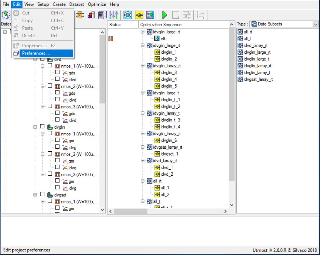
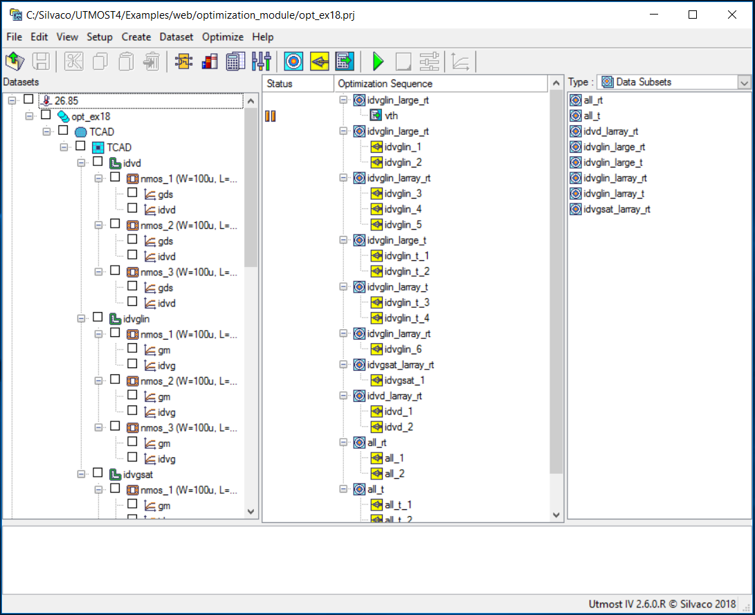
The project file opt_ex18.prj and the data file opt_ex18.uds for this example should be loaded into your database. When opened, the project will look as shown in opt_ex18_project.png .
Preliminary information
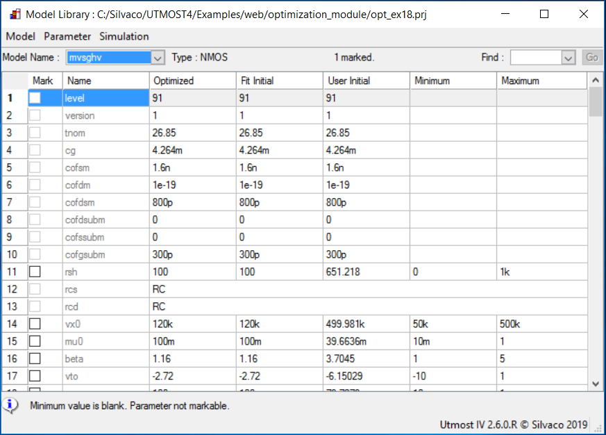
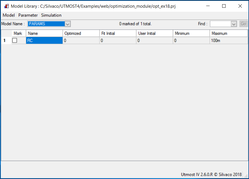
The MVSG model allows independent parameters to describe the source and drain region resistances. In order to consider symmetric devices, with the same parameter values for drain and source, respectively, one can assign two model parameters to the same netlist parameter and optimize the netlist parameter instead: opt_ex18_model_card.png and opt_ex18_netlist_parameters.png .
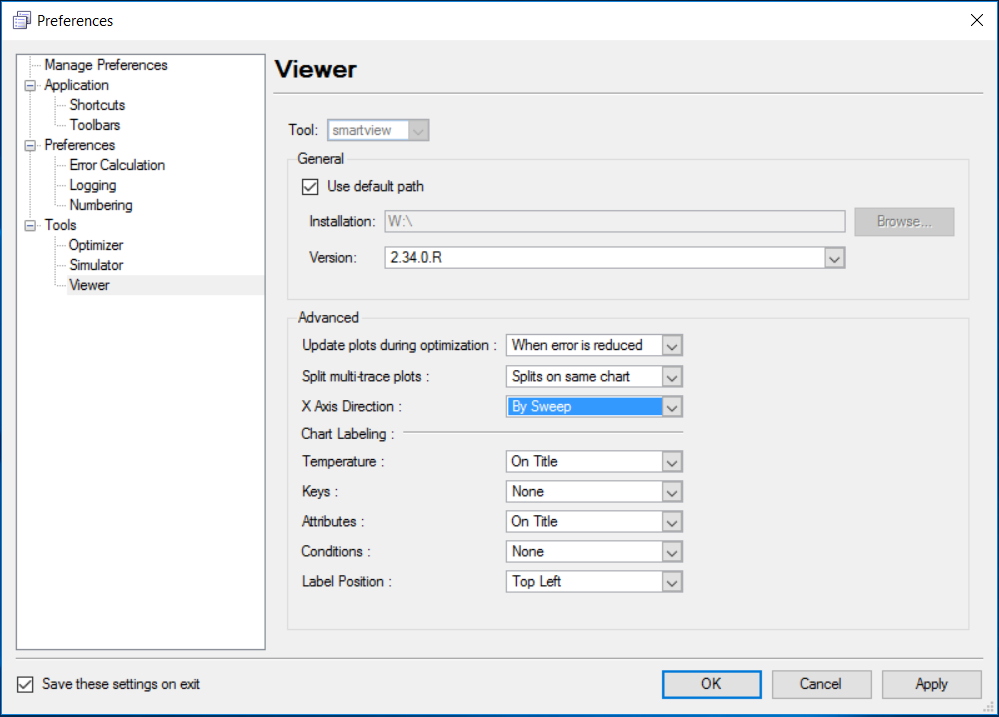
This example uses depletion mode HEMT devices. In order to better display the ID-VG plots of such devices, one needs to edit the preferences: opt_ex18_edit_preferences.png and set the X Axis Direction to "By Sweep" in the Viewer preferences: opt_ex18_preferences_x_axis.png .
The optimization sequence, which automates the parameter extraction, is divided into ten sections. The objective of each section is to isolate a device characteristic and then to optimize only those model parameters which account for this device behavior. Some model parameters are optimized in multiple sections for better fitting.
Before starting the optimization sequence, the following device parameters are defined in the model library.
- cg: Specific gate capacitance
- lgd: Drain side access region distance
- lgs: Source side access region distance
- tnom: Nominal (room) temperature
Section 1 : idvglin_large_rt
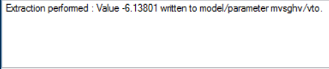
This section performs a preliminary extraction of the threshold voltage for the wide and long channel device, using the drain current versus gate voltage characteristic in the linear region and at room temperature. The extracted value is stored in the vto model parameter, as shown in opt_ex18_01.png .
Section 2 : idvglin_large_rt
This section optimizes the parameters for wide and long channel devices. The data in this section is the drain current versus gate voltage characteristic in the linear region and at room temperature. The following model parameters are extracted.
- mu0 Low-field mobility
- ss Subthreshold slope
- vto Threshold voltage
After this step has been completed, the fit to measured data will be as shown in opt_ex18_02.png .
Section 3: idvglin_larray_rt
In this section, the parameters for short channel effect are optimized using devices of multiple lengths and wide channel value. The following model parameters are extracted.
- mu0 Low-field mobility
- vto Threshold voltage
- rsh Drain/source sheet resistance
If needed, additional parameters may be considered for improved accuracy.
- mtheta Mobility reduction parameter with VG
After this step has been completed, the fit to measured data will be as shown in opt_ex18_03.png .
Section 4: idvglin_large_t
This section extracts the model parameters for the large geometry drain current versus gate voltage linear temperature measurements. The following parameters are optimized.
- vtzeta Threshold voltage dependence on temperature
- epsilon Mobility dependence on temperature
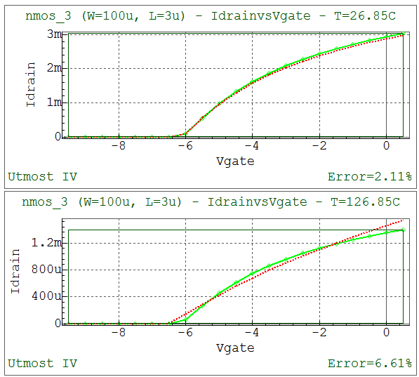
After this step has been completed, the fit to measured data will be as shown in opt_ex18_04.png .
Section 5 : idvglin_larray_t
Now we select multiple length devices at temperature for the linear drain current versus gate voltage characteristics and optimize the following parameters.
- vtzeta Threshold voltage dependence on temperature
- epsilon Mobility dependence on temperature
- rct1 Contact and sheet resistance temperature coefficient
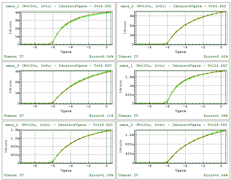
After this step has been completed, the fit to measured data will be as shown in opt_ex18_05.png .
Section 6: idvglin_larray_rt
This section is used for refining the value of the subthreshold slope parameter.
- ss Subthreshold slope
After this step has been completed, the fit to measured data will be as shown in opt_ex18_06.png .
Section 7 : idvgsat_larray_rt
The first 6 sections concentrated only on the linear regions drain current versus gate voltage for each of the different geometries. This section will use the high VDS subthreshold drain current versus gate voltage data for multiple lengths. The following parameters are optimized.
- delta1 DIBL coefficient
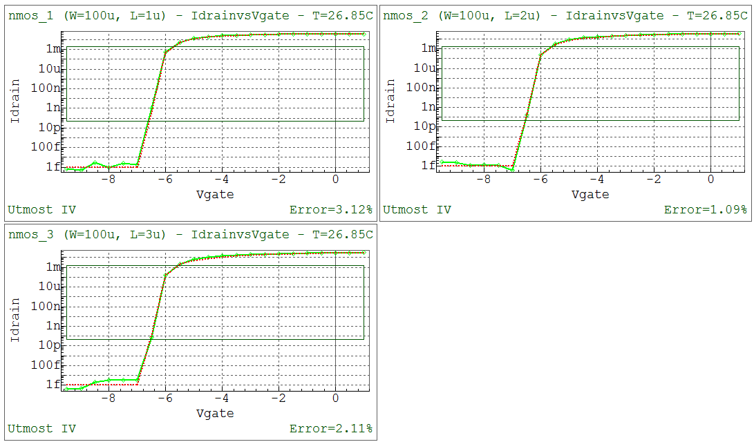
After this step has been completed, the fit to measured data will be as shown in opt_ex18_07.png .
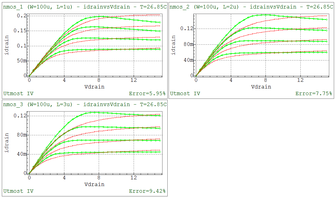
Section 8 : idvd_larray_rt
This section uses saturation region drain current versus drain voltage data for multiple lengths. The following parameters are optimized.
- vx0 Source injection velocity
- lambda Channel length modulation parameter
- delta1 DIBL coefficient
- rth Thermal resistance
After this step has been completed, the fit to measured data will be as shown in opt_ex18_08.png .
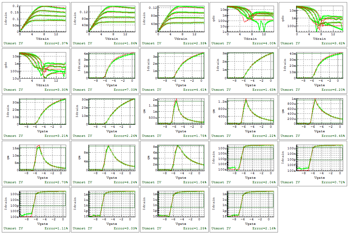
Section 9 : all_rt
This section combines room temperature data from all operation regions, in order to refine the nominal temperature parameters.
- mu0 Low-field mobility
- ss Subthreshold slope
- vto Threshold voltage
- rsh Drain/source sheet resistance
- beta Linear to saturation transition parameter
- vx0 Source injection velocity
- lambda Channel length modulation parameter
- delta1 DIBL coefficient
- rth Thermal resistance
After this step has been completed, the fit to measured data will be as shown in opt_ex18_09.png .
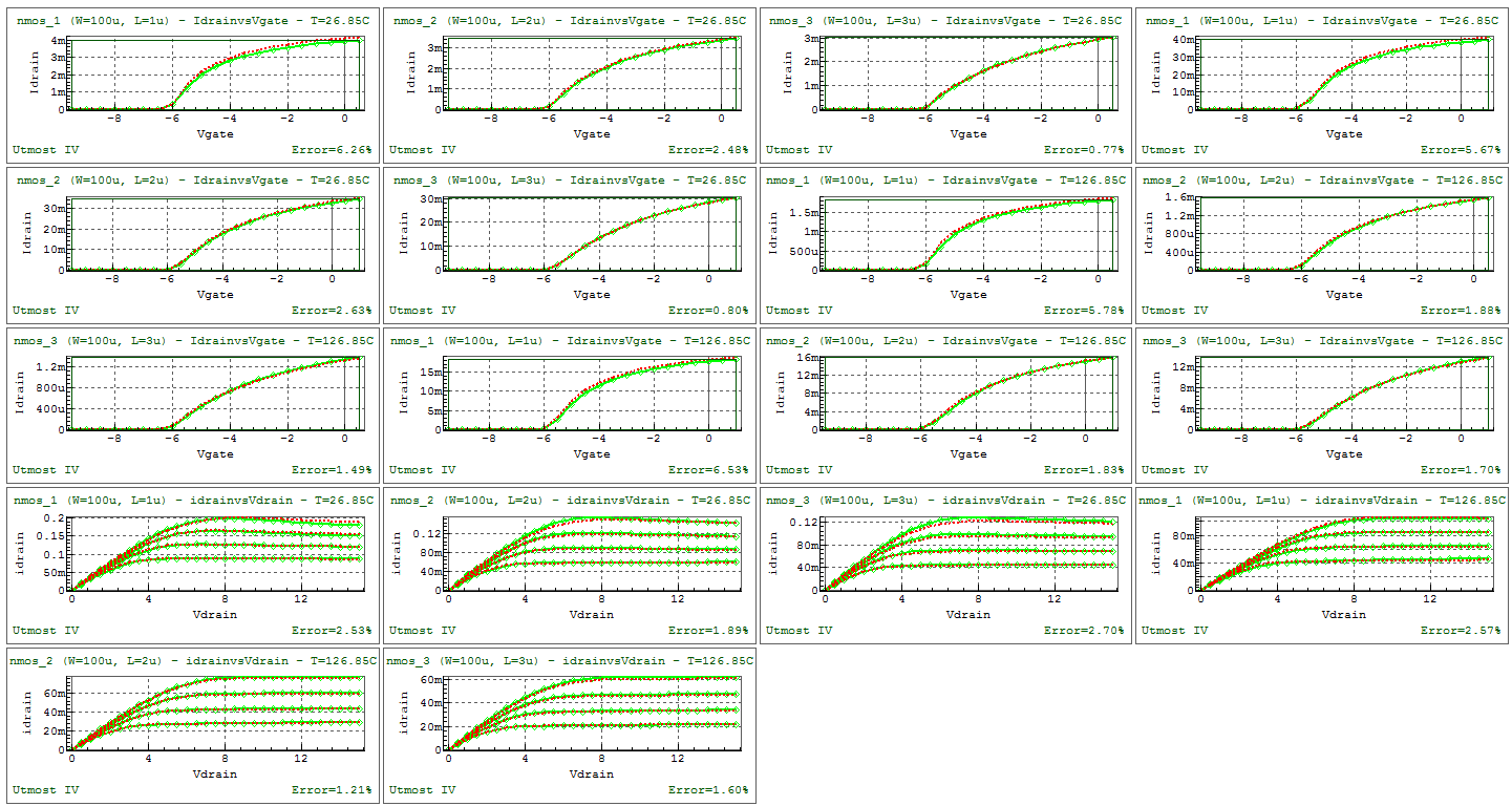
Section 10 : all_t
Finally, this section combines all temperature data to refine all previously extracted model parameters, including the thermal resistance.
- mu0 Low-field mobility
- ss Subthreshold slope
- vto Threshold voltage
- rsh Drain/source sheet resistance
- beta Linear to saturation transition parameter
- vx0 Source injection velocity
- lambda Channel length modulation parameter
- delta1 DIBL coefficient
- vtzeta Threshold voltage dependence on temperature
- epsilon Mobility dependence on temperature
- rct1 Contact and sheet resistance temperature coefficient
- rth Thermal resistance
If needed, additional parameters may be considered for an improved temperature fitting accuracy.
- vzeta Vx0 dependence on temperature
After this step has been completed, the fit to measured data will be as shown in opt_ex18_10.png .
When complete, the model card and the netlist parameters can be exported into an external model library file as shown in the output file opt_ex18.lib.
opt_ex18.lib
											.PARAM RC       = 0
.MODEL mvsghv NMOS (
+level    = 91             version  = 1              tnom     = 26.85
+cg       = 0.004264       cofsm    = 1.6e-09        cofdm    = 1e-19
+cofdsm   = 8e-10          cofdsubm = 0              cofssubm = 0
+cofgsubm = 3e-10          rsh      = 651.218        rcs      = RC
+rcd      = RC             vx0      = 499981         mu0      = 0.0396636
+beta     = 3.7045         vto      = -6.15029       ss       = 0.0797273
+delta1   = 0.0172486      delta2   = 0              dibsat   = 10
+nd       = 0              alpha    = 3.5            lambda   = 9.99983e-05
+vtheta   = 0              mtheta   = 0              vzeta    = 0.004
+vtzeta   = -0.000550215   epsilon  = 2.74741        rct1     = 0.0121881
+rct2     = 0              flagres  = 1              lgs      = 3e-06
+vtors    = -650           cgrs     = 0.0008         vx0rs    = 100000
+mu0rs    = 0.1            betars   = 1.1            delta1rs = 0.0004
+srs      = 0.065          ndrs     = 0              vthetars = 0
+mthetars = 0              alphars  = 3.5            lgd      = 3e-06
+vtord    = -650           cgrd     = 0.0007         vx0rd    = 100000
+mu0rd    = 0.1            betard   = 1.1            delta1rd = 0.0004
+srd      = 0.08           ndrd     = 0              vthetard = 0
+mthetard = 0              alphard  = 3.5            flagfp1  = 1
+lgfp1    = 0              vtofp1   = -44.5          cgfp1    = 0.0002
+flagfp1s = 1              cfp1s    = 1e-19          ccfp1    = 9e-11
+cbfp1    = 0              vx0fp1   = 120000         mu0fp1   = 0.2
+betafp1  = 1.16
+delta1fp1 = 0
+sfp1     = 3.2            ndfp1    = 0
+vthetafp1 = 0
+mthetafp1 = 0
+alphafp1 = 0.01           flagfp2  = 0              lgfp2    = 0
+vtofp2   = -60            cgfp2    = 9e-05          flagfp2s = 0
+cfp2s    = 0              ccfp2    = 6.5e-11        cbfp2    = 0
+vx0fp2   = 190000         mu0fp2   = 0.29           betafp2  = 1.16
+delta1fp2 = 0
+sfp2     = 4.1            ndfp2    = 0
+vthetafp2 = 0
+mthetafp2 = 0
+alphafp2 = 1300           flagfp3  = 1              lgfp3    = 0
+vtofp3   = -120           cgfp3    = 0.001          flagfp3s = 0
+cfp3s    = 0              ccfp3    = 0              cbfp3    = 0
+vx0fp3   = 100000         mu0fp3   = 0.17           betafp3  = 1
+delta1fp3 = 0.01
+sfp3     = 0.1            ndfp3    = 0
+vthetafp3 = 0
+mthetafp3 = 0
+alphafp3 = 3.5            flagfp4  = 1              lgfp4    = 0
+vtofp4   = -220           cgfp4    = 0.001          flagfp4s = 0
+cfp4s    = 0              ccfp4    = 0              cbfp4    = 0
+vx0fp4   = 100000         mu0fp4   = 0.17           betafp4  = 1
+delta1fp4 = 0.01
+sfp4     = 0.1            ndfp4    = 0
+vthetafp4 = 0
+mthetafp4 = 0
+alphafp4 = 3.5            rgsp     = 0              igmod    = 0
+vjg      = 1
+pg_param1 = 0.45
+pg_params = 0.3
+ijs      = 0              vgsats   = 3              fracs    = 1
+alphags  = 10
+pg_paramd = 0.38
+ijd      = 0              vgsatd   = 3              fracd    = 1
+alphagd  = 10             pgsrecs  = 0.8            irecs    = 0
+vgsatqs  = 3.4            vbdgs    = 600            pbdgs    = 4
+kbdgates = 0              betarecs = 0.35           pgsrecd  = 0.957
+irecd    = 0              vgsatqd  = 0.55           vbdgd    = 600
+pbdgd    = 4              kbdgated = 0              betarecd = 0.734
+rth      = 11.0515        cth      = 0.0001
+trapselect = 0
+vttrap   = 230            taut     = 3e-05          alphat1  = 0.0001
+alphat2  = 21             tempt    = 0.0001         noisemod = 0
+shs      = 2              shd      = 2              kf       = 0
+af       = 1              ffe      = 1              minr     = 0.001
+minl     = 1e-09          minc     = 1e-15 )
opt_ex18.uds
Utmost IV CSV Data Logfile Format Version 2 Copyright (c) 1984-2018 Silvaco, Inc. All rights reserved DataSetStart DataSetName, idvd MeasurementType, DC BatchName, opt_ex18 WaferName, TCAD DieName, TCAD DeviceName, nmos_1 Temperature, 26.85 FabDate, 25 Oct 2018 UserDate, 25 Oct 2018 Attribute, W, 0.0001 Attribute, L, 1e-06 NodeNames, drain gate source substrate Sweep, 1, V, drain, LIST, 0.1, 0 List, 1 0 0.5 1 1.5 2 2.5 3 3.5 4 4.5 5 5.5 6 6.5 7 7.5 8 8.5 9 9.5 10 10.5 11 11.5 12 12.5 13 13.5 14 14.5 15 Sweep, 2, V, gate, LIST, 0.1, 0 List, 2 -3 -2 -1 0 Constant, V, source, 0, 0.1, 0 Constant, V, substrate, 0, 0.1, 0 Target, I, drain Target, I, source Target, I, gate Target, I, substrate Function, gds, derivative (vdrain, idrain) Plot, idvd, XY (LIN LIN), vdrain, idrain Plot, gds, XY (LIN LOG), vdrain, gds DataArray, idrain 7.804408753e-16 0.01598464467 0.03089936619 0.044536357 0.05664095558 0.06674481567 0.0747152162 0.08040388706 0.08388609836 0.08572804876 0.08678528929 0.08733651223 0.08775495226 0.08795245346 0.08808631423 0.08817785268 0.08831734973 0.08834204754 0.0884367652 0.08842741285 0.08849360661 0.08846047345 0.08850436466 0.08852671173 0.08853396242 0.08852837199 0.08851126295 0.08848361245 0.08844630302 0.08840026703 0.08834656177 1.135099919e-19 0.01758157354 0.0344547526 0.05051156198 0.06561970235 0.07962158987 0.09211184905 0.1028582383 0.1115914865 0.1182999587 0.1226199325 0.1250897991 0.1261974667 0.126578865 0.1265398425 0.1262664582 0.1258635077 0.125391056 0.1248845284 0.1243649741 0.1239580092 0.1235246025 0.1230823182 0.1226385426 0.1221972909 0.1217609545 0.1213310011 0.1209083194 0.1204934073 0.1200864782 0.1197859855 -5.573978494e-16 0.01868232925 0.03685550451 0.05445685006 0.07141051005 0.08762601754 0.1029970547 0.1172644983 0.1297979823 0.1406036981 0.1494447326 0.156161807 0.1604956646 0.162921892 0.1639871576 0.1640612493 0.1635110682 0.1626068266 0.161519366 0.160349887 0.1593156225 0.158238734 0.1571605214 0.156100518 0.1550688194 0.1540703354 0.1532378983 0.1522680274 0.1514756824 0.1506814847 0.1498995544 -1.533487033e-15 0.01949210874 0.03859592351 0.05727166976 0.07547155035 0.09313889755 0.1102073071 0.1265996249 0.1422264619 0.1558569268 0.1678884479 0.1780847675 0.1862626372 0.1916863739 0.1955029221 0.1974535023 0.198119357 0.1977595498 0.1969349418 0.1953531302 0.1937986653 0.1920905577 0.1903380303 0.188599754 0.1870807071 0.1853935354 0.1839586247 0.1825464233 0.1811771607 0.179999446 0.1788185074 DataArray, igate -1.199782624e-15 -1.277757905e-15 -1.356083757e-15 -1.439309142e-15 -1.534873721e-15 -1.820503783e-15 -2.174295228e-15 -2.622828624e-15 -3.289633777e-15 -4.271122995e-15 -5.399495686e-15 -6.945541265e-15 -8.662078698e-15 -1.108299276e-14 -1.409016589e-14 -1.785495251e-14 -2.209460263e-14 -2.809060113e-14 -3.477707455e-14 -4.416692938e-14 -5.457368616e-14 -6.906533978e-14 -8.500490176e-14 -1.048154678e-13 -1.291483666e-13 -1.588625933e-13 -1.949935355e-13 -2.387745561e-13 -2.916722577e-13 -3.554297862e-13 -4.321151697e-13 -8.842360903e-16 -9.626914169e-16 -1.041150752e-15 -1.121553212e-15 -1.207113786e-15 -1.302918315e-15 -1.549059592e-15 -1.969507662e-15 -2.66225017e-15 -3.625129729e-15 -5.354026778e-15 -7.926456752e-15 -1.178477311e-14 -1.716352987e-14 -2.472684751e-14 -3.533299068e-14 -5.009353687e-14 -7.044159193e-14 -9.823560551e-14 -1.358992176e-13 -1.826962003e-13 -2.459216968e-13 -3.302576798e-13 -4.418821454e-13 -5.885780864e-13 -7.799999078e-13 -1.0280024e-12 -1.347015049e-12 -1.754462968e-12 -2.271245239e-12 -2.870514334e-12 -5.679029842e-16 -6.466105741e-16 -7.251974759e-16 -8.045230912e-16 -8.860540849e-16 -9.721094111e-16 -1.066227687e-15 -1.224351104e-15 -1.65276438e-15 -2.372896011e-15 -3.620966329e-15 -5.816641906e-15 -1.001815372e-14 -1.72757146e-14 -2.891262395e-14 -4.737358775e-14 -7.625109378e-14 -1.208186799e-13 -1.886303076e-13 -2.901843929e-13 -4.30425848e-13 -6.348110607e-13 -9.267761447e-13 -1.337936268e-12 -1.910132613e-12 -2.698335816e-12 -3.706241104e-12 -5.177790115e-12 -7.016035705e-12 -9.487677904e-12 -1.27604186e-11 -1.07705963e-31 -3.29909166e-16 -4.086411756e-16 -4.875251786e-16 -5.672737253e-16 -6.489952721e-16 -7.34386479e-16 -8.259632836e-16 -9.274164175e-16 -1.319001076e-15 -1.99118395e-15 -3.2138923e-15 -5.533940979e-15 -1.084848789e-14 -2.055396441e-14 -3.946244907e-14 -7.335664885e-14 -1.326049086e-13 -2.276753399e-13 -3.950278677e-13 -6.513389741e-13 -1.060371106e-12 -1.69829722e-12 -2.672668943e-12 -4.053849752e-12 -6.209728013e-12 -9.144208253e-12 -1.334442968e-11 -1.924382282e-11 -2.698369745e-11 -3.772171109e-11 DataArray, isource -9.477188186e-16 -0.01598464467 -0.03089936619 -0.044536357 -0.05664095558 -0.06674481567 -0.0747152162 -0.08040388706 -0.08388609836 -0.08572804876 -0.08678528929 -0.08733651223 -0.08775495225 -0.08795245346 -0.08808631423 -0.08817785268 -0.08831734973 -0.08834204754 -0.0884367652 -0.08842741285 -0.08849360661 -0.08846047346 -0.08850436465 -0.08852671173 -0.08853396242 -0.08852837199 -0.08851126295 -0.08848361244 -0.08844630302 -0.08840026703 -0.08834656177 6.070821887e-16 -0.01758157354 -0.0344547526 -0.05051156198 -0.06561970235 -0.07962158987 -0.09211184905 -0.1028582383 -0.1115914865 -0.1182999587 -0.1226199325 -0.1250897991 -0.1261974667 -0.126578865 -0.1265398425 -0.1262664582 -0.1258635077 -0.125391056 -0.1248845284 -0.1243649741 -0.1239580092 -0.1235246025 -0.1230823182 -0.1226385426 -0.1221972909 -0.1217609545 -0.1213310011 -0.1209083194 -0.1204934073 -0.1200864782 -0.1197859855 5.421532316e-16 -0.01868232925 -0.03685550451 -0.05445685006 -0.07141051047 -0.08762601768 -0.1029970548 -0.1172644983 -0.1297979823 -0.1406036981 -0.1494447326 -0.156161807 -0.1604956646 -0.162921892 -0.1639871576 -0.1640612493 -0.1635110682 -0.1626068266 -0.161519366 -0.160349887 -0.1593156225 -0.158238734 -0.1571605214 -0.156100518 -0.1550688194 -0.1540703354 -0.1532378983 -0.1522680274 -0.1514756824 -0.1506814847 -0.1498995544 -8.396237672e-16 -0.01949210874 -0.03859592351 -0.05727166976 -0.07547155078 -0.09313889768 -0.1102073072 -0.126599625 -0.142226462 -0.1558569268 -0.1678884479 -0.1780847675 -0.1862626372 -0.1916863739 -0.1955029221 -0.1974535023 -0.198119357 -0.1977595498 -0.1969349418 -0.1953531302 -0.1937986653 -0.1920905577 -0.1903380303 -0.188599754 -0.1870807071 -0.1853935354 -0.1839586247 -0.1825464232 -0.1811771607 -0.179999446 -0.1788185074 DataArray, isubstrate 2.226966063e-40 -1.891213099e-27 -2.239474274e-27 -2.553687978e-27 -2.8571739e-27 -3.153778565e-27 -3.443704575e-27 -3.725902608e-27 -3.999493369e-27 -4.265445546e-27 -4.526725005e-27 -4.784722543e-27 -5.041228729e-27 -5.295939867e-27 -5.549685577e-27 -5.802702432e-27 -6.055617865e-27 -6.307548888e-27 -6.559563727e-27 -6.810629583e-27 -7.061811098e-27 -7.312003344e-27 -7.562313941e-27 -7.812158851e-27 -8.061569304e-27 -8.310577318e-27 -8.559225017e-27 -8.80756586e-27 -9.05565659e-27 -9.303546683e-27 -9.551273386e-27 1.603936949e-40 -1.900261977e-27 -2.245570499e-27 -2.560165035e-27 -2.865927376e-27 -3.167061664e-27 -3.464446949e-27 -3.757516617e-27 -4.045376858e-27 -4.327458432e-27 -4.601598473e-27 -4.86830576e-27 -5.128610437e-27 -5.384892591e-27 -5.638457357e-27 -5.890129638e-27 -6.140399082e-27 -6.389599774e-27 -6.637975903e-27 -6.885698187e-27 -7.133686663e-27 -7.38113928e-27 -7.628139898e-27 -7.874737217e-27 -8.120962295e-27 -8.366838613e-27 -8.612389899e-27 -8.857645441e-27 -9.102638723e-27 -9.347401568e-27 -9.592785812e-27 1.036041456e-40 -1.905606659e-27 -2.248980784e-27 -2.56353756e-27 -2.870098229e-27 -3.172804646e-27 -3.472899978e-27 -3.770578649e-27 -4.064155123e-27 -4.353228991e-27 -4.637215612e-27 -4.915193263e-27 -5.18513054e-27 -5.447694176e-27 -5.704438788e-27 -5.95636639e-27 -6.20475935e-27 -6.450722894e-27 -6.695019611e-27 -6.938123646e-27 -7.181571537e-27 -7.424205063e-27 -7.666251617e-27 -7.907875891e-27 -8.14918647e-27 -8.390280634e-27 -8.63234149e-27 -8.873100439e-27 -9.114972556e-27 -9.356762775e-27 -9.598551683e-27 -4.195843739e-44 -1.909154128e-27 -2.251172209e-27 -2.565613345e-27 -2.872531606e-27 -3.175954916e-27 -3.47715491e-27 -3.776604794e-27 -4.074446162e-27 -4.366852001e-27 -4.654638931e-27 -4.937324184e-27 -5.214143859e-27 -5.480862013e-27 -5.742005745e-27 -5.99546798e-27 -6.243405153e-27 -6.486387292e-27 -6.727436126e-27 -6.963434818e-27 -7.19967208e-27 -7.434650141e-27 -7.668934667e-27 -7.902923233e-27 -8.138487473e-27 -8.372311371e-27 -8.608022736e-27 -8.843936879e-27 -9.080247251e-27 -9.318406307e-27 -9.556979303e-27 DataSetFinish DataSetStart DataSetName, idvd MeasurementType, DC BatchName, opt_ex18 WaferName, TCAD DieName, TCAD DeviceName, nmos_2 Temperature, 26.85 FabDate, 25 Oct 2018 UserDate, 25 Oct 2018 Attribute, W, 0.0001 Attribute, L, 2e-06 NodeNames, drain gate source substrate Sweep, 1, V, drain, LIST, 0.1, 0 List, 1 0 0.5 1 1.5 2 2.5 3 3.5 4 4.5 5 5.5 6 6.5 7 7.5 8 8.5 9 9.5 10 10.5 11 11.5 12 12.5 13 13.5 14 14.5 15 Sweep, 2, V, gate, LIST, 0.1, 0 List, 2 -3 -2 -1 0 Constant, V, source, 0, 0.1, 0 Constant, V, substrate, 0, 0.1, 0 Target, I, drain Target, I, source Target, I, gate Target, I, substrate Function, gds, derivative (vdrain, idrain) Plot, idvd, XY (LIN LIN), vdrain, idrain Plot, gds, XY (LIN LOG), vdrain, gds DataArray, idrain 2.841363162e-15 0.01230817484 0.02345174113 0.03326724267 0.04155961471 0.04805292469 0.0526366621 0.05539870529 0.05682665326 0.05742500218 0.05779735875 0.0580616107 0.05822324124 0.05840635812 0.05856216319 0.0586563199 0.05879021921 0.05886521531 0.05898066033 0.05908084988 0.05912570612 0.05921323217 0.05928639695 0.0593481368 0.05939993136 0.05944295662 0.05947836993 0.05950736597 0.05953111952 0.05955069723 0.05956699512 1.762049038e-15 0.01416580212 0.02749142367 0.03987811897 0.05120906355 0.06134726469 0.07006030409 0.07711525477 0.08234707694 0.085878182 0.08793802679 0.0887746392 0.08914835825 0.08920692085 0.08917386082 0.08908870025 0.08904419077 0.08889315404 0.08880906971 0.08863707943 0.08853840898 0.08842529289 0.08830321627 0.08817498566 0.08804222316 0.08790590786 0.08776664325 0.08762480467 0.08748062767 0.08733426443 0.08724968332 5.139117395e-16 0.0155394475 0.03044094511 0.04464085387 0.05806495194 0.07062687243 0.08222688077 0.09275174943 0.1016696742 0.1089699262 0.1146822604 0.1187710294 0.1209721435 0.1219053094 0.1220168542 0.1217944235 0.1214001577 0.1210315172 0.1204845824 0.1200372303 0.1195659943 0.1190876376 0.1186108832 0.1181403313 0.1176783441 0.1172260665 0.1168715246 0.1165022269 0.116039937 0.1156873428 0.1153268937 -6.479793381e-16 0.01659965053 0.03269531864 0.04824358349 0.06319429613 0.07748973222 0.09106368511 0.103840628 0.1157350401 0.1263289127 0.1351219932 0.1422717425 0.147905273 0.1519966702 0.1538867914 0.1547116697 0.1547191645 0.1542050703 0.1532425409 0.1523531608 0.1513939565 0.1504167981 0.1494485195 0.1486271322 0.1477971064 0.1469756103 0.1461708198 0.1453865873 0.1446244693 0.1438847869 0.1431672154 DataArray, igate -2.243809579e-15 -2.389317737e-15 -2.53314641e-15 -2.679519802e-15 -2.835339635e-15 -3.120492791e-15 -3.467125474e-15 -3.865756954e-15 -4.289176194e-15 -5.024814504e-15 -5.696928494e-15 -6.392585518e-15 -7.284595544e-15 -8.096706266e-15 -9.026193245e-15 -1.027894616e-14 -1.145304781e-14 -1.305584565e-14 -1.456689816e-14 -1.631418643e-14 -1.866570093e-14 -2.086842478e-14 -2.340056291e-14 -2.627810098e-14 -2.953440006e-14 -3.321240404e-14 -3.73636812e-14 -4.20480001e-14 -4.733292043e-14 -5.329354037e-14 -6.001259339e-14 -1.653686119e-15 -1.80025404e-15 -1.945747865e-15 -2.092139612e-15 -2.242742338e-15 -2.402795211e-15 -2.666236731e-15 -3.122437524e-15 -3.854989249e-15 -4.746802401e-15 -5.799441409e-15 -7.439029505e-15 -9.233658989e-15 -1.155915655e-14 -1.427096183e-14 -1.750834149e-14 -2.098876537e-14 -2.578174388e-14 -3.092801109e-14 -3.801489335e-14 -4.564095739e-14 -5.502183776e-14 -6.644882355e-14 -8.029061868e-14 -9.698260847e-14 -1.170295262e-13 -1.410111171e-13 -1.695896879e-13 -2.035203039e-13 -2.436651688e-13 -2.854409243e-13 -1.06208653e-15 -1.209202686e-15 -1.35552063e-15 -1.501950922e-15 -1.650096275e-15 -1.802514878e-15 -1.963109582e-15 -2.137730452e-15 -2.631203076e-15 -3.42526566e-15 -4.518283104e-15 -6.025284638e-15 -8.680859088e-15 -1.243932845e-14 -1.764531806e-14 -2.42694903e-14 -3.285487458e-14 -4.31548198e-14 -5.7985342e-14 -7.565746494e-14 -9.881970671e-14 -1.28909276e-13 -1.678260071e-13 -2.179948586e-13 -2.82448748e-13 -3.649176236e-13 -4.61038658e-13 -5.846606494e-13 -7.556540334e-13 -9.495616557e-13 -1.194065199e-12 -1.476436705e-31 -6.168848251e-16 -7.638204175e-16 -9.10344095e-16 -1.057347377e-15 -1.206104572e-15 -1.358582467e-15 -1.5176973e-15 -1.687705211e-15 -2.021323596e-15 -2.784815618e-15 -4.055522615e-15 -5.973282978e-15 -8.893163084e-15 -1.482692494e-14 -2.350314621e-14 -3.601763876e-14 -5.385669165e-14 -8.10168797e-14 -1.16669311e-13 -1.671711367e-13 -2.380459498e-13 -3.365406097e-13 -4.627197909e-13 -6.362373438e-13 -8.715240752e-13 -1.187849499e-12 -1.610219692e-12 -2.170635167e-12 -2.90950547e-12 -3.877214232e-12 DataArray, isource 5.563362608e-16 -0.01230817484 -0.02345174113 -0.03326724267 -0.04155961471 -0.04805292469 -0.0526366621 -0.05539870529 -0.05682665326 -0.05742500218 -0.05779735875 -0.0580616107 -0.05822324124 -0.05840635812 -0.05856216319 -0.0586563199 -0.0587902192 -0.05886521531 -0.05898066033 -0.05908084988 -0.05912570612 -0.05921323217 -0.05928639695 -0.0593481368 -0.05939993136 -0.05944295662 -0.05947836993 -0.05950736598 -0.05953111952 -0.05955069723 -0.05956699512 8.963395703e-16 -0.01416580212 -0.02749142367 -0.03987811897 -0.05120906355 -0.06134726469 -0.07006030409 -0.07711525477 -0.08234707694 -0.085878182 -0.08793802679 -0.0887746392 -0.08914835825 -0.08920692085 -0.08917386082 -0.08908870025 -0.08904419077 -0.08889315404 -0.08880906971 -0.08863707943 -0.08853840898 -0.08842529288 -0.08830321627 -0.08817498566 -0.08804222316 -0.08790590786 -0.08776664325 -0.08762480467 -0.08748062767 -0.08733426443 -0.08724968332 2.154611714e-16 -0.0155394475 -0.03044094511 -0.04464085387 -0.05806495234 -0.07062687257 -0.08222688088 -0.09275174943 -0.1016696742 -0.1089699262 -0.1146822604 -0.1187710294 -0.1209721435 -0.1219053094 -0.1220168542 -0.1217944235 -0.1214001577 -0.1210315172 -0.1204845824 -0.1200372303 -0.1195659943 -0.1190876376 -0.1186108832 -0.1181403313 -0.1176783441 -0.1172260665 -0.1168715246 -0.1165022269 -0.116039937 -0.1156873428 -0.1153268937 4.660739025e-16 -0.01659965053 -0.03269531864 -0.04824358349 -0.06319429653 -0.07748973234 -0.09106368518 -0.1038406281 -0.1157350402 -0.1263289127 -0.1351219932 -0.1422717425 -0.147905273 -0.1519966702 -0.1538867914 -0.1547116697 -0.1547191645 -0.1542050703 -0.1532425409 -0.1523531608 -0.1513939565 -0.1504167981 -0.1494485195 -0.1486271322 -0.1477971064 -0.1469756103 -0.1461708198 -0.1453865873 -0.1446244693 -0.1438847869 -0.1431672154 DataArray, isubstrate 5.636856575e-40 -2.129902879e-27 -2.526245639e-27 -2.877672663e-27 -3.212811639e-27 -3.53503727e-27 -3.842840963e-27 -4.13413803e-27 -4.410654559e-27 -4.677693362e-27 -4.940386597e-27 -5.200695385e-27 -5.459247698e-27 -5.717106447e-27 -5.974253741e-27 -6.230567417e-27 -6.486788114e-27 -6.742258272e-27 -6.99770421e-27 -7.252739657e-27 -7.507021335e-27 -7.761301977e-27 -8.015154356e-27 -8.268601407e-27 -8.521667901e-27 -8.774387361e-27 -9.026804891e-27 -9.278975797e-27 -9.530956057e-27 -9.782791524e-27 -1.003451437e-26 4.024975459e-40 -2.146672412e-27 -2.537913815e-27 -2.890507903e-27 -3.231026197e-27 -3.564163876e-27 -3.890340436e-27 -4.208261544e-27 -4.515617146e-27 -4.810528469e-27 -5.092411096e-27 -5.36271714e-27 -5.626597089e-27 -5.886275077e-27 -6.143782214e-27 -6.399788607e-27 -6.655229033e-27 -6.909297018e-27 -7.16333966e-27 -7.416307746e-27 -7.669423116e-27 -7.922069639e-27 -8.174285581e-27 -8.42609861e-27 -8.677531552e-27 -8.928609242e-27 -9.179359574e-27 -9.429817018e-27 -9.68001919e-27 -9.930000806e-27 -1.018036788e-26 2.553068198e-40 -2.156587195e-27 -2.544358365e-27 -2.897063881e-27 -3.239511839e-27 -3.576478834e-27 -3.909184041e-27 -4.237660876e-27 -4.560209671e-27 -4.875304241e-27 -5.182049203e-27 -5.47877697e-27 -5.762587305e-27 -6.035141413e-27 -6.29888235e-27 -6.557503542e-27 -6.812945121e-27 -7.067141509e-27 -7.318964006e-27 -7.570542306e-27 -7.821197009e-27 -8.071175354e-27 -8.320630815e-27 -8.569670898e-27 -8.818366183e-27 -9.066771048e-27 -9.315678097e-27 -9.564257481e-27 -9.811868606e-27 -1.006017555e-26 -1.030829921e-26 -8.755359802e-43 -2.163138935e-27 -2.548449134e-27 -2.901023191e-27 -3.244338128e-27 -3.58305355e-27 -3.918546723e-27 -4.251204551e-27 -4.580959352e-27 -4.90629221e-27 -5.224567454e-27 -5.535631721e-27 -5.839392847e-27 -6.134598533e-27 -6.416275561e-27 -6.688486451e-27 -6.952169873e-27 -7.209344076e-27 -7.460912804e-27 -7.711075294e-27 -7.95935986e-27 -8.206391225e-27 -8.45252282e-27 -8.699085386e-27 -8.945041016e-27 -9.190659296e-27 -9.436125363e-27 -9.681592692e-27 -9.927202941e-27 -1.017308775e-26 -1.041936793e-26 DataSetFinish DataSetStart DataSetName, idvd MeasurementType, DC BatchName, opt_ex18 WaferName, TCAD DieName, TCAD DeviceName, nmos_3 Temperature, 26.85 FabDate, 25 Oct 2018 UserDate, 25 Oct 2018 Attribute, W, 0.0001 Attribute, L, 3e-06 NodeNames, drain gate source substrate Sweep, 1, V, drain, LIST, 0.1, 0 List, 1 0 0.5 1 1.5 2 2.5 3 3.5 4 4.5 5 5.5 6 6.5 7 7.5 8 8.5 9 9.5 10 10.5 11 11.5 12 12.5 13 13.5 14 14.5 15 Sweep, 2, V, gate, LIST, 0.1, 0 List, 2 -3 -2 -1 0 Constant, V, source, 0, 0.1, 0 Constant, V, substrate, 0, 0.1, 0 Target, I, drain Target, I, source Target, I, gate Target, I, substrate Function, gds, derivative (vdrain, idrain) Plot, idvd, XY (LIN LIN), vdrain, idrain Plot, gds, XY (LIN LOG), vdrain, gds DataArray, idrain 6.008411602e-17 0.01000607771 0.01889248747 0.02653413941 0.03278763855 0.03750037577 0.04052755327 0.04212370469 0.04284806468 0.04321987964 0.04342245274 0.04358296004 0.04372084576 0.04384526823 0.04396040564 0.04404062006 0.04414732727 0.04424505518 0.04433499518 0.04441752436 0.04446612249 0.0445404672 0.04460641329 0.0446658496 0.04471998995 0.04476990215 0.04481648452 0.04486043114 0.0449022376 0.04494223183 0.04498060992 6.675883907e-16 0.01186106327 0.02286718817 0.03293520246 0.04196959648 0.0498611674 0.05648903732 0.06165176848 0.06524406039 0.06744335047 0.06857813906 0.06903675696 0.06918710416 0.06925518391 0.06928438046 0.06924442132 0.0692533789 0.06925165493 0.06924313173 0.06922947839 0.069211477 0.06918951415 0.06916379362 0.06913442158 0.06910144406 0.06906487426 0.06902472394 0.06898104224 0.06893395804 0.06892501044 0.06886172914 1.271521268e-15 0.01330156126 0.02592698716 0.03781883151 0.04891172968 0.05913133897 0.06839346767 0.07660432137 0.08356579449 0.08899574291 0.09304138463 0.09572994698 0.09711618857 0.09749773979 0.097536046 0.09741458217 0.0972229636 0.09700049993 0.09676515179 0.09652607065 0.09628811594 0.09605361061 0.09582345485 0.09559785296 0.09543696337 0.09520484252 0.0950410368 0.09480985231 0.09464650834 0.09447543296 0.0942999591 1.874291174e-16 0.01445459478 0.02835891494 0.04167169784 0.0543463534 0.06633035753 0.0775645816 0.08798269854 0.09751091268 0.1059552097 0.1130022034 0.1186223978 0.1227368714 0.1255547171 0.1270156635 0.1272803077 0.1270851408 0.1266488035 0.1261076199 0.1255297446 0.1249466934 0.1244654268 0.123884055 0.1234152446 0.1229468346 0.1224849053 0.1220320313 0.1215892943 0.1211570525 0.1208105053 0.12037898 DataArray, igate -3.28783626e-15 -3.500570719e-15 -3.708393478e-15 -3.913861885e-15 -4.121278298e-15 -4.33671564e-15 -4.733856048e-15 -5.125154545e-15 -5.496121408e-15 -5.852790206e-15 -6.344700375e-15 -6.814368246e-15 -7.293433171e-15 -7.796326299e-15 -8.333367592e-15 -9.05635536e-15 -9.657017048e-15 -1.032288283e-14 -1.105214922e-14 -1.184808725e-14 -1.292895161e-14 -1.383479066e-14 -1.484120226e-14 -1.594548501e-14 -1.715384368e-14 -1.847459233e-14 -1.991715861e-14 -2.149178967e-14 -2.320949452e-14 -2.508208748e-14 -2.712227447e-14 -2.423135942e-15 -2.637623502e-15 -2.849238945e-15 -3.059346546e-15 -3.270376582e-15 -3.486273439e-15 -3.713140085e-15 -4.103947732e-15 -4.737922852e-15 -5.441835798e-15 -6.194285612e-15 -7.18498116e-15 -8.393595445e-15 -9.654232817e-15 -1.102632486e-14 -1.277920451e-14 -1.445873197e-14 -1.639286715e-14 -1.862113513e-14 -2.119212932e-14 -2.415944806e-14 -2.758162674e-14 -3.152291122e-14 -3.605430682e-14 -4.12547975e-14 -4.721281173e-14 -5.402806962e-14 -6.18139356e-14 -7.070029138e-14 -7.933370609e-14 -9.121964738e-14 -1.556269939e-15 -1.771669798e-15 -1.985133913e-15 -2.197304776e-15 -2.409433733e-15 -2.623603005e-15 -2.843054338e-15 -3.072706995e-15 -3.428801034e-15 -4.156969681e-15 -5.074831607e-15 -6.221619453e-15 -7.871430121e-15 -1.032897035e-14 -1.307476234e-14 -1.626179785e-14 -2.005046773e-14 -2.461818476e-14 -3.016110315e-14 -3.690797004e-14 -4.514271888e-14 -5.521981848e-14 -6.757109185e-14 -8.271043945e-14 -9.934597385e-14 -1.223580449e-13 -1.472749238e-13 -1.813679669e-13 -2.1798728e-13 -2.627070129e-13 -3.166454977e-13 -6.45935427e-32 -9.036547362e-16 -1.118524188e-15 -1.331827618e-15 -1.544509077e-15 -1.757643241e-15 -1.972944587e-15 -2.192998554e-15 -2.421616618e-15 -2.743970677e-15 -3.361606601e-15 -4.343567908e-15 -5.904022497e-15 -8.030330414e-15 -1.125662012e-14 -1.635721986e-14 -2.279370359e-14 -3.102133639e-14 -4.166108156e-14 -5.553793855e-14 -7.370778573e-14 -9.557366476e-14 -1.268819683e-13 -1.640780704e-13 -2.127291998e-13 -2.758603978e-13 -3.574417346e-13 -4.624551994e-13 -5.970382976e-13 -7.543212691e-13 -9.753697036e-13 DataArray, isource 8.668133797e-16 -0.01000607771 -0.01889248747 -0.02653413941 -0.03278763855 -0.03750037577 -0.04052755327 -0.04212370469 -0.04284806468 -0.04321987964 -0.04342245274 -0.04358296004 -0.04372084576 -0.04384526823 -0.04396040564 -0.04404062006 -0.04414732727 -0.04424505518 -0.04433499518 -0.04441752436 -0.04446612249 -0.0445404672 -0.04460641329 -0.0446658496 -0.04471998995 -0.04476990215 -0.04481648452 -0.04486043114 -0.0449022376 -0.04494223183 -0.04498060992 5.827469964e-16 -0.01186106327 -0.02286718817 -0.03293520246 -0.04196959648 -0.0498611674 -0.05648903732 -0.06165176848 -0.06524406039 -0.06744335047 -0.06857813906 -0.06903675696 -0.06918710416 -0.06925518391 -0.06928438046 -0.06924442132 -0.0692533789 -0.06925165493 -0.06924313172 -0.06922947839 -0.069211477 -0.06918951414 -0.06916379362 -0.06913442158 -0.06910144406 -0.06906487426 -0.06902472394 -0.06898104224 -0.06893395804 -0.06892501044 -0.06886172914 1.383949897e-15 -0.01330156126 -0.02592698716 -0.03781883151 -0.04891173007 -0.0591313391 -0.06839346778 -0.07660432137 -0.08356579449 -0.08899574291 -0.09304138463 -0.09572994698 -0.09711618857 -0.09749773979 -0.097536046 -0.09741458217 -0.0972229636 -0.09700049993 -0.09676515179 -0.09652607065 -0.09628811594 -0.09605361061 -0.09582345485 -0.09559785296 -0.09543696337 -0.09520484252 -0.0950410368 -0.09480985231 -0.09464650834 -0.09447543296 -0.0942999591 -1.650229081e-16 -0.01445459478 -0.02835891494 -0.04167169784 -0.05434635379 -0.06633035765 -0.07756458167 -0.08798269861 -0.09751091277 -0.1059552097 -0.1130022034 -0.1186223978 -0.1227368714 -0.1255547171 -0.1270156635 -0.1272803077 -0.1270851408 -0.1266488035 -0.1261076199 -0.1255297446 -0.1249466934 -0.1244654268 -0.123884055 -0.1234152446 -0.1229468346 -0.1224849053 -0.1220320313 -0.1215892943 -0.1211570525 -0.1208105053 -0.12037898 DataArray, isubstrate 1.087323241e-39 -2.369110739e-27 -2.812362486e-27 -3.199992452e-27 -3.56507852e-27 -3.910433685e-27 -4.231822594e-27 -4.527460104e-27 -4.803831732e-27 -5.071053494e-27 -5.33414099e-27 -5.595293743e-27 -5.855198354e-27 -6.11427697e-27 -6.372767038e-27 -6.630512144e-27 -6.88814319e-27 -7.145336517e-27 -7.402123004e-27 -7.65851342e-27 -7.914197711e-27 -8.169859025e-27 -8.425105152e-27 -8.679971394e-27 -8.934487148e-27 -9.188685826e-27 -9.442608717e-27 -9.696306005e-27 -9.949829367e-27 -1.020322198e-26 -1.045651469e-26 7.635511948e-40 -2.393172095e-27 -2.829872318e-27 -3.219872687e-27 -3.594091167e-27 -3.957556899e-27 -4.310105662e-27 -4.648981971e-27 -4.970457478e-27 -5.272158679e-27 -5.555397921e-27 -5.82604685e-27 -6.090151569e-27 -6.351206186e-27 -6.61039781e-27 -6.867880254e-27 -7.125004163e-27 -7.381454909e-27 -7.637382844e-27 -7.892849967e-27 -8.147877244e-27 -8.402470516e-27 -8.656636363e-27 -8.910391973e-27 -9.163756271e-27 -9.416754358e-27 -9.669417991e-27 -9.921786953e-27 -1.017390411e-26 -1.042632314e-26 -1.06779423e-26 4.765013068e-40 -2.407554129e-27 -2.839504793e-27 -3.229985446e-27 -3.607635049e-27 -3.97778203e-27 -4.341463287e-27 -4.698241227e-27 -5.046344801e-27 -5.382435935e-27 -5.704680085e-27 -6.010678402e-27 -6.299082002e-27 -6.572498872e-27 -6.837741953e-27 -7.098305953e-27 -7.356162317e-27 -7.612269776e-27 -7.867108862e-27 -8.121003285e-27 -8.374198927e-27 -8.626850645e-27 -8.879043212e-27 -9.130832005e-27 -9.382915623e-27 -9.633859327e-27 -9.885229518e-27 -1.013557212e-26 -1.038644228e-26 -1.063704821e-26 -1.088746322e-26 4.615442919e-43 -2.417086985e-27 -2.845583892e-27 -3.236043153e-27 -3.615290329e-27 -3.9885491e-27 -4.357224458e-27 -4.721522699e-27 -5.081047264e-27 -5.434454837e-27 -5.778891973e-27 -6.112746469e-27 -6.433738815e-27 -6.741061295e-27 -7.03242945e-27 -7.308093105e-27 -7.573995244e-27 -7.833482605e-27 -8.089093981e-27 -8.342329243e-27 -8.593992729e-27 -8.8454185e-27 -9.094840773e-27 -9.344584481e-27 -9.593702827e-27 -9.842400196e-27 -1.009080581e-26 -1.03390155e-26 -1.058710963e-26 -1.083597055e-26 -1.108382798e-26 DataSetFinish DataSetStart DataSetName, idvgsat MeasurementType, DC_TABLE BatchName, opt_ex18 WaferName, TCAD DieName, TCAD DeviceName, nmos_1 Temperature, 26.85 FabDate, 25 Oct 2018 UserDate, 25 Oct 2018 Attribute, W, 0.0001 Attribute, L, 1e-06 NodeNames, gate drain source substrate Sweep, 1, V, gate, LIST, 0.1, 0 List, 1 -9.5 -9 -8.5 -8 -7.5 -7 -6.5 -6 -5.5 -5 -4.5 -4 -3.5 -3 -2.5 -2 -1.5 -1 -0.5 1.285828941e-15 0.5 1 Sweep, 2, V, drain, LIST, 0.1, 0 List, 2 1 1 1 1 1 1 1 1 1 1 1 1 1 1 1 1 1 1 1 1 1 1 Sweep, 3, V, source, LIST, 0.1, 0 List, 3 0 0 0 0 0 0 0 0 0 0 0 0 0 0 0 0 0 0 0 0 0 0 Sweep, 4, V, substrate, LIST, 0.1, 0 List, 4 0 0 0 0 0 0 0 0 0 0 0 0 0 0 0 0 0 0 0 0 0 0 Target, I, gate Target, I, drain Target, I, source Target, I, substrate Function, gm, derivative (vgate, idrain) Plot, idvg, XY (LIN LIN), vgate, idrain Plot, gm, XY (LIN LIN), vgate, gm DataArray, Idrain -6.360009627e-16 5.219768933e-16 2.963049426e-15 8.787694837e-16 2.647174923e-15 1.733761207e-15 1.070831291e-09 0.0005193135882 0.005682942323 0.01387101811 0.0204603608 0.02505486119 0.02838397518 0.03090068394 0.03287039468 0.03445571162 0.03576106598 0.03685635674 0.03779004619 0.0385967571 0.03930186888 0.03992436292 DataArray, Igate -2.226392413e-15 -2.216404508e-15 -2.20640791e-15 -2.196399885e-15 -2.186374313e-15 -2.176320974e-15 -2.166222891e-15 -2.138486806e-15 -2.056872377e-15 -1.951039965e-15 -1.813496192e-15 -1.663767928e-15 -1.509921715e-15 -1.354251882e-15 -1.197608045e-15 -1.040375004e-15 -8.827531536e-16 -7.24857959e-16 -5.667611982e-16 -4.085101845e-16 1.1369271e-15 9.190771385e-08 DataArray, Isource 2.123805395e-15 3.41209609e-16 1.182346984e-15 -9.03889484e-16 1.931400107e-15 1.408510669e-15 -1.07082896e-09 -0.0005193135882 -0.005682942323 -0.01387101811 -0.0204603608 -0.02505486119 -0.02838397518 -0.03090068394 -0.03287039468 -0.03445571184 -0.03576106605 -0.03685635676 -0.0377900462 -0.03859675711 -0.03930186888 -0.03992445482 DataArray, Isubstrate 1.029248239e-17 8.269284467e-19 1.612531313e-20 6.868995839e-23 4.64807605e-26 -1.415142734e-27 -1.473329519e-27 -1.634829213e-27 -2.005947671e-27 -2.163881866e-27 -2.208268281e-27 -2.225335593e-27 -2.23410353e-27 -2.239406247e-27 -2.242954151e-27 -2.24549585e-27 -2.247408548e-27 -2.248902305e-27 -2.250103146e-27 -2.251091186e-27 -2.251919758e-27 -2.252626059e-27 DataSetFinish DataSetStart DataSetName, idvgsat MeasurementType, DC_TABLE BatchName, opt_ex18 WaferName, TCAD DieName, TCAD DeviceName, nmos_2 Temperature, 26.85 FabDate, 25 Oct 2018 UserDate, 25 Oct 2018 Attribute, W, 0.0001 Attribute, L, 2e-06 NodeNames, gate drain source substrate Sweep, 1, V, gate, LIST, 0.1, 0 List, 1 -9.5 -9 -8.5 -8 -7.5 -7 -6.5 -6 -5.5 -5 -4.5 -4 -3.5 -3 -2.5 -2 -1.5 -1 -0.5 1.285828941e-15 0.5 1 Sweep, 2, V, drain, LIST, 0.1, 0 List, 2 1 1 1 1 1 1 1 1 1 1 1 1 1 1 1 1 1 1 1 1 1 1 Sweep, 3, V, source, LIST, 0.1, 0 List, 3 0 0 0 0 0 0 0 0 0 0 0 0 0 0 0 0 0 0 0 0 0 0 Sweep, 4, V, substrate, LIST, 0.1, 0 List, 4 0 0 0 0 0 0 0 0 0 0 0 0 0 0 0 0 0 0 0 0 0 0 Target, I, gate Target, I, drain Target, I, source Target, I, substrate Function, gm, derivative (vgate, idrain) Plot, idvg, XY (LIN LIN), vgate, idrain Plot, gm, XY (LIN LIN), vgate, gm DataArray, Idrain 2.707195276e-15 2.109484273e-15 1.131883833e-15 1.392796834e-15 1.158621018e-15 4.10758329e-16 1.64727002e-10 0.0002344895655 0.003076952908 0.008426957446 0.01352404712 0.01757405953 0.02081280983 0.02345256493 0.02564375768 0.0274920534 0.02907294424 0.03044151237 0.03163878021 0.03269588008 0.03363684344 0.03448023291 DataArray, Igate -4.113728834e-15 -4.101182914e-15 -4.08862795e-15 -4.076061304e-15 -4.063476898e-15 -4.050864002e-15 -4.038205532e-15 -3.990899782e-15 -3.83269801e-15 -3.638516092e-15 -3.385582041e-15 -3.107773338e-15 -2.821320315e-15 -2.530957718e-15 -2.238494275e-15 -1.94476429e-15 -1.650205541e-15 -1.3550703e-15 -1.05951467e-15 -7.636406876e-16 1.378647983e-14 7.014214228e-07 DataArray, Isource 1.006620888e-15 1.04082038e-15 1.307676374e-15 2.776339598e-15 2.968203795e-15 1.889642617e-15 -1.647213887e-10 -0.0002344895655 -0.003076952909 -0.008426957446 -0.01352404712 -0.01757405953 -0.02081280983 -0.02345256493 -0.02564375768 -0.02749205352 -0.02907294429 -0.03044151239 -0.03163878022 -0.03269588008 -0.03363684344 -0.03448093433 DataArray, Isubstrate 8.260728005e-16 5.534121955e-16 2.175889372e-16 9.337482773e-18 2.710768775e-21 2.029025059e-27 -1.561235608e-27 -1.782155132e-27 -2.149835252e-27 -2.383797018e-27 -2.466079478e-27 -2.498970395e-27 -2.515952979e-27 -2.526190288e-27 -2.533001351e-27 -2.537850125e-27 -2.541475732e-27 -2.544289506e-27 -2.54653776e-27 -2.548376677e-27 -2.549909931e-27 -2.551212245e-27 DataSetFinish DataSetStart DataSetName, idvgsat MeasurementType, DC_TABLE BatchName, opt_ex18 WaferName, TCAD DieName, TCAD DeviceName, nmos_3 Temperature, 26.85 FabDate, 25 Oct 2018 UserDate, 25 Oct 2018 Attribute, W, 0.0001 Attribute, L, 3e-06 NodeNames, gate drain source substrate Sweep, 1, V, gate, LIST, 0.1, 0 List, 1 -9.5 -9 -8.5 -8 -7.5 -7 -6.5 -6 -5.5 -5 -4.5 -4 -3.5 -3 -2.5 -2 -1.5 -1 -0.5 1.285828941e-15 0.5 1 Sweep, 2, V, drain, LIST, 0.1, 0 List, 2 1 1 1 1 1 1 1 1 1 1 1 1 1 1 1 1 1 1 1 1 1 1 Sweep, 3, V, source, LIST, 0.1, 0 List, 3 0 0 0 0 0 0 0 0 0 0 0 0 0 0 0 0 0 0 0 0 0 0 Sweep, 4, V, substrate, LIST, 0.1, 0 List, 4 0 0 0 0 0 0 0 0 0 0 0 0 0 0 0 0 0 0 0 0 0 0 Target, I, gate Target, I, drain Target, I, source Target, I, substrate Function, gm, derivative (vgate, idrain) Plot, idvg, XY (LIN LIN), vgate, idrain Plot, gm, XY (LIN LIN), vgate, gm DataArray, Idrain -4.35470087e-16 4.940279275e-16 2.185294457e-15 3.407511756e-15 3.192768776e-15 3.390473276e-15 8.044291577e-11 0.0001496811188 0.002100941652 0.006036673192 0.01008695632 0.01352394777 0.01642364539 0.01889301357 0.02101878064 0.02286761899 0.02449064471 0.02592738847 0.02720878138 0.02835931992 0.02939863151 0.03034152524 DataArray, Igate -5.99950689e-15 -5.984600144e-15 -5.969684326e-15 -5.95475681e-15 -5.939811528e-15 -5.924837724e-15 -5.909818314e-15 -5.842418511e-15 -5.606119077e-15 -5.322591286e-15 -4.954773331e-15 -4.549472119e-15 -4.130893343e-15 -3.706212644e-15 -3.278217442e-15 -2.84821176e-15 -2.416887343e-15 -1.984645822e-15 -1.551736911e-15 -1.118323597e-15 8.123720593e-14 3.110131238e-06 DataArray, Isource 1.021231313e-15 7.532998212e-16 1.338623771e-15 2.006740756e-15 2.426065754e-15 3.219485578e-15 -8.043781151e-11 -0.0001496811188 -0.002100941652 -0.006036673192 -0.01008695632 -0.01352394777 -0.01642364539 -0.01889301357 -0.02101878082 -0.02286761905 -0.02449064473 -0.02592738848 -0.02720878138 -0.02835931993 -0.02939863151 -0.03034463537 DataArray, Isubstrate 2.47020831e-15 2.084091886e-15 1.469264907e-15 4.178675557e-16 1.912620551e-19 4.491835698e-26 -1.652149533e-27 -1.954734734e-27 -2.336691612e-27 -2.610583626e-27 -2.723599881e-27 -2.771642237e-27 -2.796958578e-27 -2.812315455e-27 -2.822543507e-27 -2.829816544e-27 -2.835243099e-27 -2.839443303e-27 -2.842789546e-27 -2.845518265e-27 -2.847786476e-27 -2.849720491e-27 DataSetFinish DataSetStart DataSetName, idvglin MeasurementType, DC_TABLE BatchName, opt_ex18 WaferName, TCAD DieName, TCAD DeviceName, nmos_1 Temperature, 26.85 FabDate, 25 Oct 2018 UserDate, 25 Oct 2018 Attribute, W, 0.0001 Attribute, L, 1e-06 NodeNames, gate drain source substrate Sweep, 1, V, gate, LIST, 0.1, 0 List, 1 -9.5 -9 -8.5 -8 -7.5 -7 -6.5 -6 -5.5 -5 -4.5 -4 -3.5 -3 -2.5 -2 -1.5 -1 -0.5 1.285828941e-15 0.5 Sweep, 2, V, drain, LIST, 0.1, 0 List, 2 0.1 0.1 0.1 0.1 0.1 0.1 0.1 0.1 0.1 0.1 0.1 0.1 0.1 0.1 0.1 0.1 0.1 0.1 0.1 0.1 0.1 Sweep, 3, V, source, LIST, 0.1, 0 List, 3 0 0 0 0 0 0 0 0 0 0 0 0 0 0 0 0 0 0 0 0 0 Sweep, 4, V, substrate, LIST, 0.1, 0 List, 4 0 0 0 0 0 0 0 0 0 0 0 0 0 0 0 0 0 0 0 0 0 Target, I, gate Target, I, drain Target, I, source Target, I, substrate Function, gm, derivative (vgate, idrain) Plot, idvg, XY (LIN LIN), vgate, idrain Plot, gm, XY (LIN LIN), vgate, gm DataArray, Idrain -4.269914863e-16 -5.055471376e-16 1.001645272e-15 1.419556461e-15 -1.989449854e-17 1.419441286e-15 4.343532918e-10 0.000277599559 0.001292014284 0.00199390335 0.0024716737 0.002814800358 0.003072847473 0.003274114723 0.003435709599 0.003568525542 0.003679810772 0.003774569037 0.003856363606 0.003927799926 0.003990824923 DataArray, Igate -2.219700941e-15 -2.209703592e-15 -2.199696263e-15 -2.189675125e-15 -2.17963045e-15 -2.169545262e-15 -2.159396508e-15 -2.123735817e-15 -1.989859044e-15 -1.839449337e-15 -1.685240067e-15 -1.529415425e-15 -1.372713727e-15 -1.215467792e-15 -1.057854183e-15 -8.999770339e-16 -7.419025409e-16 -5.836752083e-16 -4.25326292e-16 -2.271716373e-16 4.027671477e-09 DataArray, Isource 5.566608865e-16 3.373221197e-16 1.595726029e-15 1.335686143e-15 5.783086936e-16 1.152380412e-15 -4.343524506e-10 -0.000277599559 -0.001292014284 -0.00199390335 -0.0024716737 -0.002814800358 -0.003072847473 -0.003274114723 -0.003435709602 -0.003568525543 -0.003679810773 -0.003774569037 -0.003856363606 -0.003927799926 -0.003990828951 DataArray, Isubstrate 4.012218825e-17 7.079145815e-18 2.772737685e-19 1.759111708e-21 1.237539243e-24 -8.752542198e-28 -9.496938265e-28 -1.065349883e-27 -1.186258808e-27 -1.245292723e-27 -1.278684357e-27 -1.299786236e-27 -1.314211375e-27 -1.324653053e-27 -1.33254508e-27 -1.33871432e-27 -1.343668503e-27 -1.347735456e-27 -1.35113574e-27 -1.354022913e-27 -1.356507177e-27 DataSetFinish DataSetStart DataSetName, idvglin MeasurementType, DC_TABLE BatchName, opt_ex18 WaferName, TCAD DieName, TCAD DeviceName, nmos_2 Temperature, 26.85 FabDate, 25 Oct 2018 UserDate, 25 Oct 2018 Attribute, W, 0.0001 Attribute, L, 2e-06 NodeNames, gate drain source substrate Sweep, 1, V, gate, LIST, 0.1, 0 List, 1 -9.5 -9 -8.5 -8 -7.5 -7 -6.5 -6 -5.5 -5 -4.5 -4 -3.5 -3 -2.5 -2 -1.5 -1 -0.5 1.285828941e-15 0.5 Sweep, 2, V, drain, LIST, 0.1, 0 List, 2 0.1 0.1 0.1 0.1 0.1 0.1 0.1 0.1 0.1 0.1 0.1 0.1 0.1 0.1 0.1 0.1 0.1 0.1 0.1 0.1 0.1 Sweep, 3, V, source, LIST, 0.1, 0 List, 3 0 0 0 0 0 0 0 0 0 0 0 0 0 0 0 0 0 0 0 0 0 Sweep, 4, V, substrate, LIST, 0.1, 0 List, 4 0 0 0 0 0 0 0 0 0 0 0 0 0 0 0 0 0 0 0 0 0 Target, I, gate Target, I, drain Target, I, source Target, I, substrate Function, gm, derivative (vgate, idrain) Plot, idvg, XY (LIN LIN), vgate, idrain Plot, gm, XY (LIN LIN), vgate, gm DataArray, Idrain 1.294469916e-15 2.558836092e-15 5.036557624e-16 1.363416662e-15 1.794752134e-15 2.604720191e-15 1.203115468e-10 0.0001455489759 0.0007778089494 0.001308459684 0.001724482851 0.002055697333 0.002324902228 0.002547906652 0.002735716747 0.002896152792 0.003034898134 0.003156172546 0.003263170662 0.003358353574 0.003443643431 DataArray, Igate -4.10683804e-15 -4.094282122e-15 -4.081715757e-15 -4.069135211e-15 -4.056530618e-15 -4.043883886e-15 -4.031170258e-15 -3.970696287e-15 -3.721113115e-15 -3.439975248e-15 -3.151641791e-15 -2.860255464e-15 -2.567214113e-15 -2.273147049e-15 -1.978387734e-15 -1.683132642e-15 -1.38750655e-15 -1.091593281e-15 -7.954516676e-16 -4.22330596e-16 7.742031806e-09 DataArray, Isource 1.422270014e-15 2.967547199e-15 2.054018097e-15 1.632747287e-15 1.536007501e-15 1.222621592e-15 -1.203075086e-10 -0.0001455489759 -0.0007778089494 -0.001308459684 -0.001724482851 -0.002055697333 -0.002324902228 -0.002547906656 -0.002735716748 -0.002896152792 -0.003034898134 -0.003156172546 -0.003263170662 -0.003358353574 -0.003443651173 DataArray, Isubstrate 1.014696777e-15 7.364974751e-16 3.570540543e-16 2.744516957e-17 9.226915049e-21 6.981277175e-27 -1.038241004e-27 -1.211456651e-27 -1.318903486e-27 -1.378528503e-27 -1.417979362e-27 -1.445779605e-27 -1.466296043e-27 -1.481992546e-27 -1.494353035e-27 -1.504318801e-27 -1.512512926e-27 -1.519362782e-27 -1.525170457e-27 -1.530155056e-27 -1.534479486e-27 DataSetFinish DataSetStart DataSetName, idvglin MeasurementType, DC_TABLE BatchName, opt_ex18 WaferName, TCAD DieName, TCAD DeviceName, nmos_3 Temperature, 26.85 FabDate, 25 Oct 2018 UserDate, 25 Oct 2018 Attribute, W, 0.0001 Attribute, L, 3e-06 NodeNames, gate drain source substrate Sweep, 1, V, gate, LIST, 0.1, 0 List, 1 -9.5 -9 -8.5 -8 -7.5 -7 -6.5 -6 -5.5 -5 -4.5 -4 -3.5 -3 -2.5 -2 -1.5 -1 -0.5 1.285828941e-15 0.5 Sweep, 2, V, drain, LIST, 0.1, 0 List, 2 0.1 0.1 0.1 0.1 0.1 0.1 0.1 0.1 0.1 0.1 0.1 0.1 0.1 0.1 0.1 0.1 0.1 0.1 0.1 0.1 0.1 Sweep, 3, V, source, LIST, 0.1, 0 List, 3 0 0 0 0 0 0 0 0 0 0 0 0 0 0 0 0 0 0 0 0 0 Sweep, 4, V, substrate, LIST, 0.1, 0 List, 4 0 0 0 0 0 0 0 0 0 0 0 0 0 0 0 0 0 0 0 0 0 Target, I, gate Target, I, drain Target, I, source Target, I, substrate Function, gm, derivative (vgate, idrain) Plot, idvg, XY (LIN LIN), vgate, idrain Plot, gm, XY (LIN LIN), vgate, gm DataArray, Idrain 2.150328571e-15 2.675291677e-16 1.403126045e-15 3.114629478e-15 4.137788559e-15 3.813254246e-15 6.695184855e-11 9.857058568e-05 0.0005563397805 0.0009736923434 0.001324157592 0.001619046505 0.001869774471 0.002085356642 0.002272672524 0.002436976693 0.002582322474 0.002711875169 0.002828137564 0.002933112255 0.003028414167 DataArray, Igate -5.99259835e-15 -5.977681557e-15 -5.962754282e-15 -5.94781279e-15 -5.93284721e-15 -5.917839375e-15 -5.902764395e-15 -5.817611361e-15 -5.45233553e-15 -5.04047469e-15 -4.61802383e-15 -4.19108172e-15 -3.761705347e-15 -3.330820675e-15 -2.898918315e-15 -2.466287293e-15 -2.033111131e-15 -1.599513096e-15 -1.165579685e-15 -6.148628915e-16 1.168064043e-08 DataArray, Isource 1.338078716e-15 1.978371937e-15 2.378449442e-15 3.839222024e-15 3.34642243e-15 3.269480832e-15 -6.694441806e-11 -9.857058568e-05 -0.0005563397805 -0.0009736923434 -0.001324157592 -0.001619046505 -0.001869774471 -0.002085356643 -0.002272672525 -0.002436976694 -0.002582322474 -0.002711875169 -0.002828137564 -0.002933112255 -0.003028425848 DataArray, Isubstrate 2.709635764e-15 2.343500152e-15 1.741171292e-15 6.009168131e-16 3.312714885e-19 6.941815287e-26 -1.126955022e-27 -1.367923252e-27 -1.473829774e-27 -1.530903945e-27 -1.571520603e-27 -1.602000798e-27 -1.625647228e-27 -1.644469307e-27 -1.659768855e-27 -1.672425314e-27 -1.68305285e-27 -1.692092289e-27 -1.699867559e-27 -1.706621589e-27 -1.712540628e-27 DataSetFinish DataSetStart DataSetName, idvd MeasurementType, DC BatchName, opt_ex18 WaferName, TCAD DieName, TCAD DeviceName, nmos_1 Temperature, 126.85 FabDate, 25 Oct 2018 UserDate, 25 Oct 2018 Attribute, W, 0.0001 Attribute, L, 1e-06 NodeNames, drain gate source substrate Sweep, 1, V, drain, LIST, 0.1, 0 List, 1 0 0.5 1 1.5 2 2.5 3 3.5 4 4.5 5 5.5 6 6.5 7 7.5 8 8.5 9 9.5 10 10.5 11 11.5 12 12.5 13 13.5 14 14.5 15 Sweep, 2, V, gate, LIST, 0.1, 0 List, 2 -3 -2 -1 0 Constant, V, source, 0, 0.1, 0 Constant, V, substrate, 0, 0.1, 0 Target, I, drain Target, I, source Target, I, gate Target, I, substrate Function, gds, derivative (vdrain, idrain) Plot, idvd, XY (LIN LIN), vdrain, idrain Plot, gds, XY (LIN LOG), vdrain, gds DataArray, idrain 1.420462999e-11 0.007344947092 0.01420164208 0.0204784112 0.02606080049 0.03081573861 0.03458186621 0.03734153575 0.03916923796 0.04031469872 0.04106315241 0.04157021321 0.04197489452 0.04231735863 0.04262128899 0.04290009605 0.04316151397 0.04340997446 0.04364795948 0.04387683395 0.0440973466 0.04430991288 0.0445147696 0.04471206371 0.04490191144 0.04508444584 0.04525985921 0.04542843951 0.04559059298 0.04574684413 0.04589780838 1.048603553e-11 0.00807670893 0.01582895138 0.02320877664 0.03015751748 0.0366041259 0.0424651624 0.0476010797 0.05195596959 0.05545226923 0.05806665815 0.05981070792 0.06091307089 0.06164667023 0.06215374387 0.06252559862 0.06281438295 0.06305013055 0.0632018041 0.06338994331 0.06355662412 0.06370942304 0.06385192842 0.06398618217 0.06411340917 0.06423437164 0.0643495592 0.06445929327 0.06456378701 0.06466318247 0.06475757604 6.757859028e-12 0.008581912458 0.01693016518 0.02501684196 0.03280851413 0.04026531303 0.04734004209 0.05397759963 0.06011493155 0.06553489456 0.07028773014 0.07429736942 0.07751245211 0.07983407349 0.08137558324 0.08239180785 0.08303543631 0.08335959592 0.08362882661 0.08372065163 0.08383890919 0.08390820082 0.08387801267 0.08391394221 0.0839302776 0.08393551985 0.0839336559 0.08392695574 0.0839167891 0.08390400352 0.08388913143 2.996231416e-16 0.008953797286 0.01772923856 0.02630862891 0.03467109333 0.042792121 0.05064305247 0.05819055632 0.0653961237 0.07221560072 0.07851154702 0.08418482288 0.08914941427 0.09345658207 0.09705148669 0.09964101937 0.1015649052 0.1028782424 0.1036988051 0.1040511626 0.1042986714 0.1042787425 0.1042809145 0.1042084285 0.104091256 0.1039469941 0.1037869095 0.1036183933 0.1034462944 0.1032737421 0.1031026833 DataArray, igate -2.848627008e-11 -3.03271544e-11 -3.215787217e-11 -3.402317247e-11 -3.598349044e-11 -3.810590155e-11 -4.178190703e-11 -4.528395707e-11 -4.874271624e-11 -5.215916035e-11 -5.561181389e-11 -6.041796175e-11 -6.515609662e-11 -7.016306279e-11 -7.55286633e-11 -8.13134029e-11 -8.757228524e-11 -9.435809062e-11 -1.017213304e-10 -1.097105125e-10 -1.183730944e-10 -1.27756716e-10 -1.379104239e-10 -1.488858633e-10 -1.607385297e-10 -1.735291427e-10 -1.873250937e-10 -2.022017911e-10 -2.182436403e-10 -2.355444191e-10 -2.542069979e-10 -2.10349552e-11 -2.288920781e-11 -2.473599673e-11 -2.65962222e-11 -2.850279861e-11 -3.050330865e-11 -3.266197343e-11 -3.621478473e-11 -4.016738105e-11 -4.464224277e-11 -4.964002918e-11 -5.686504883e-11 -6.553180691e-11 -7.43513889e-11 -8.390477111e-11 -9.444547302e-11 -1.06154926e-10 -1.191931912e-10 -1.362449414e-10 -1.518946228e-10 -1.697170667e-10 -1.897506621e-10 -2.121947018e-10 -2.372948666e-10 -2.653221974e-10 -2.965685298e-10 -3.313464897e-10 -3.699909027e-10 -4.128608339e-10 -4.60342289e-10 -5.128517831e-10 -1.355773146e-11 -1.541914131e-11 -1.72743502e-11 -1.91326573e-11 -2.100995566e-11 -2.293070252e-11 -2.493037029e-11 -2.705845302e-11 -2.938181866e-11 -3.436744475e-11 -3.995571788e-11 -4.650581548e-11 -5.425379724e-11 -6.534209843e-11 -7.967254103e-11 -9.550619402e-11 -1.135408312e-10 -1.371313958e-10 -1.605245521e-10 -1.917886795e-10 -2.228667077e-10 -2.593286296e-10 -3.073164865e-10 -3.545809521e-10 -4.097916287e-10 -4.734737976e-10 -5.466333082e-10 -6.304877302e-10 -7.264086767e-10 -8.359098068e-10 -9.606499145e-10 5.002647973e-27 -7.922406953e-12 -9.790747237e-12 -1.16495754e-11 -1.351402784e-11 -1.539620555e-11 -1.731433835e-11 -1.929459776e-11 -2.137345972e-11 -2.36007844e-11 -2.697159147e-11 -3.208760967e-11 -3.956692166e-11 -4.860482612e-11 -5.978770411e-11 -7.830374681e-11 -1.001820355e-10 -1.266403336e-10 -1.586319971e-10 -2.016361063e-10 -2.472489656e-10 -3.090529893e-10 -3.744471468e-10 -4.536155603e-10 -5.481379873e-10 -6.602159537e-10 -7.924698143e-10 -9.479616945e-10 -1.130264499e-09 -1.343535093e-09 -1.592570427e-09 DataArray, isource 1.428167938e-11 -0.007344947062 -0.01420164205 -0.02047841116 -0.02606080046 -0.03081573858 -0.03458186616 -0.0373415357 -0.03916923791 -0.04031469867 -0.04106315235 -0.04157021315 -0.04197489446 -0.04231735856 -0.04262128891 -0.04290009597 -0.04316151388 -0.04340997437 -0.04364795937 -0.04387683384 -0.04409734649 -0.04430991276 -0.04451476946 -0.04471206356 -0.04490191128 -0.04508444566 -0.04525985902 -0.0454284393 -0.04559059276 -0.04574684389 -0.04589780813 1.054875343e-11 -0.008076708907 -0.01582895135 -0.02320877661 -0.03015751745 -0.03660412587 -0.04246516237 -0.04760107967 -0.05195596954 -0.05545226919 -0.0580666581 -0.05981070786 -0.06091307082 -0.06164667016 -0.06215374379 -0.06252559852 -0.06281438284 -0.06305013043 -0.06320180397 -0.06338994316 -0.06355662395 -0.06370942285 -0.06385192821 -0.06398618193 -0.06411340891 -0.06423437135 -0.06434955887 -0.0644592929 -0.0645637866 -0.06466318201 -0.06475757552 6.799742932e-12 -0.008581912443 -0.01693016517 -0.02501684194 -0.03280851451 -0.04026531316 -0.04734004214 -0.05397759966 -0.06011493159 -0.06553489452 -0.0702877301 -0.07429736938 -0.07751245206 -0.07983407343 -0.08137558316 -0.08239180776 -0.0830354362 -0.08335959578 -0.08362882645 -0.08372065144 -0.08383890897 -0.08390820056 -0.08387801236 -0.08391394185 -0.08393027719 -0.08393551937 -0.08393365535 -0.08392695511 -0.08391678838 -0.08390400269 -0.08388913047 -4.458629728e-17 -0.008953797278 -0.01772923855 -0.0263086289 -0.03467109374 -0.04279212114 -0.05064305251 -0.05819055633 -0.0653961237 -0.07221560073 -0.07851154699 -0.08418482284 -0.08914941423 -0.09345658203 -0.09705148663 -0.09964101929 -0.1015649051 -0.1028782422 -0.103698805 -0.1040511624 -0.1042986711 -0.1042787422 -0.1042809142 -0.104208428 -0.1040912554 -0.1039469934 -0.1037869087 -0.1036183923 -0.1034462933 -0.1032737408 -0.1031026817 DataArray, isubstrate 1.817009945e-28 -3.979295798e-20 -4.798118798e-20 -5.520592461e-20 -6.212816349e-20 -6.886548748e-20 -7.543264903e-20 -8.182087792e-20 -8.802239014e-20 -9.406587125e-20 -1.000037906e-19 -1.058749163e-19 -1.117065616e-19 -1.175111578e-19 -1.232965383e-19 -1.290678853e-19 -1.34828588e-19 -1.405807404e-19 -1.463254709e-19 -1.520632712e-19 -1.577942656e-19 -1.63518382e-19 -1.692355165e-19 -1.749455933e-19 -1.806486987e-19 -1.86345097e-19 -1.920352096e-19 -1.977195779e-19 -2.033988303e-19 -2.090736659e-19 -2.147448299e-19 1.32485922e-28 -4.004375281e-20 -4.815150029e-20 -5.537705391e-20 -6.234580394e-20 -6.918100883e-20 -7.591758697e-20 -8.256028614e-20 -8.910339199e-20 -9.552942146e-20 -1.018198676e-19 -1.07962973e-19 -1.139789951e-19 -1.199058369e-19 -1.257718435e-19 -1.315960792e-19 -1.373900027e-19 -1.431610941e-19 -1.489079878e-19 -1.546486429e-19 -1.603779554e-19 -1.660980023e-19 -1.71809941e-19 -1.775143277e-19 -1.832114556e-19 -1.889015114e-19 -1.945846673e-19 -2.002611374e-19 -2.059312316e-19 -2.115953999e-19 -2.172542483e-19 8.46743743e-29 -4.019356453e-20 -4.824731912e-20 -5.546680321e-20 -6.245009167e-20 -6.931789251e-20 -7.610926582e-20 -8.283947327e-20 -8.951250638e-20 -9.611472538e-20 -1.026459197e-19 -1.090922972e-19 -1.15437347e-19 -1.216577691e-19 -1.277511453e-19 -1.337400961e-19 -1.396468289e-19 -1.454835896e-19 -1.512884434e-19 -1.570498818e-19 -1.627975518e-19 -1.6852444e-19 -1.74224139e-19 -1.799223551e-19 -1.856089736e-19 -1.912861964e-19 -1.969555205e-19 -2.026180094e-19 -2.082744676e-19 -2.139255597e-19 -2.195718978e-19 1.64216484e-35 -4.029356991e-20 -4.830904578e-20 -5.552218603e-20 -6.251093015e-20 -6.939264972e-20 -7.620692428e-20 -8.29710422e-20 -8.969260757e-20 -9.637359567e-20 -1.030063459e-19 -1.095834922e-19 -1.160953694e-19 -1.225405057e-19 -1.289063319e-19 -1.351531291e-19 -1.412984034e-19 -1.473400913e-19 -1.532880697e-19 -1.591447418e-19 -1.649598942e-19 -1.707160701e-19 -1.764556427e-19 -1.821682062e-19 -1.87859244e-19 -1.935329701e-19 -1.991927612e-19 -2.048413199e-19 -2.104809217e-19 -2.161134855e-19 -2.217406391e-19 DataSetFinish DataSetStart DataSetName, idvd MeasurementType, DC BatchName, opt_ex18 WaferName, TCAD DieName, TCAD DeviceName, nmos_2 Temperature, 126.85 FabDate, 25 Oct 2018 UserDate, 25 Oct 2018 Attribute, W, 0.0001 Attribute, L, 2e-06 NodeNames, drain gate source substrate Sweep, 1, V, drain, LIST, 0.1, 0 List, 1 0 0.5 1 1.5 2 2.5 3 3.5 4 4.5 5 5.5 6 6.5 7 7.5 8 8.5 9 9.5 10 10.5 11 11.5 12 12.5 13 13.5 14 14.5 15 Sweep, 2, V, gate, LIST, 0.1, 0 List, 2 -3 -2 -1 0 Constant, V, source, 0, 0.1, 0 Constant, V, substrate, 0, 0.1, 0 Target, I, drain Target, I, source Target, I, gate Target, I, substrate Function, gds, derivative (vdrain, idrain) Plot, idvd, XY (LIN LIN), vdrain, idrain Plot, gds, XY (LIN LOG), vdrain, gds DataArray, idrain 2.658048887e-11 0.005656865279 0.0107808034 0.01529876632 0.0191247857 0.02216240314 0.02433521379 0.02568008499 0.02638771207 0.02679067182 0.02705900174 0.02726581572 0.02744064693 0.02759680125 0.02774094392 0.02787657006 0.02800550811 0.02812869481 0.02824660411 0.02835948085 0.02846746466 0.02857066194 0.02866919812 0.02876326068 0.02885312939 0.02893918378 0.02902188087 0.02910170854 0.02917913277 0.02925455742 0.02932830497 1.962231555e-11 0.006508076335 0.01263075571 0.01832352169 0.02353429245 0.02820222732 0.0322576273 0.03562696633 0.03820580683 0.04003061796 0.04118887112 0.04187706977 0.04230069985 0.04255448846 0.04274890989 0.04290806992 0.04304525192 0.04316801111 0.04328082356 0.04338634582 0.0434861208 0.04358102365 0.04367154635 0.04375796709 0.04384044287 0.04391905937 0.04399386135 0.04406487618 0.04413213556 0.04422342499 0.04427583488 1.264504976e-11 0.007138474917 0.0139839736 0.02050772713 0.02667654443 0.03245209853 0.03779018857 0.04264032039 0.04694645999 0.05059669921 0.05358230189 0.05587419677 0.05749443861 0.05847330931 0.05901377761 0.05934491519 0.05955669092 0.05970041098 0.05980349061 0.05988114736 0.05994241752 0.05999291352 0.06003615675 0.06007432921 0.06010874925 0.06014019269 0.06016910924 0.06019575824 0.06022028624 0.0602803802 0.06029119846 -3.648753344e-18 0.007625359681 0.01501914206 0.02216173137 0.02903075436 0.03560070691 0.04184251008 0.04772304802 0.05320478247 0.05824565389 0.06279958364 0.06666185687 0.06992268436 0.07254735296 0.07453036842 0.07582111626 0.07655952239 0.07698765469 0.077218085 0.07733124194 0.07737557595 0.07737880167 0.07735698561 0.0773198911 0.07727370865 0.0772224012 0.07716846331 0.07716412963 0.07709625805 0.07708324866 0.07701038475 DataArray, igate -5.32741037e-11 -5.670841685e-11 -6.008130871e-11 -6.342278836e-11 -6.676996356e-11 -7.014204473e-11 -7.349283141e-11 -7.669645901e-11 -8.169575527e-11 -8.533863421e-11 -8.856720337e-11 -9.167624199e-11 -9.480348027e-11 -9.801837847e-11 -1.013598386e-10 -1.048516189e-10 -1.085085732e-10 -1.123397839e-10 -1.163506853e-10 -1.205447032e-10 -1.249244758e-10 -1.294927534e-10 -1.342531293e-10 -1.39210668e-10 -1.443723511e-10 -1.497471848e-10 -1.553458841e-10 -1.611802439e-10 -1.672624552e-10 -1.736046027e-10 -1.802184338e-10 -3.933907488e-11 -4.280265357e-11 -4.623111161e-11 -4.9640921e-11 -5.305980801e-11 -5.652798222e-11 -6.009608998e-11 -6.381576243e-11 -6.979359601e-11 -7.566531748e-11 -8.135804111e-11 -8.679563041e-11 -9.207262687e-11 -9.926169989e-11 -1.060820157e-10 -1.129644918e-10 -1.200814372e-10 -1.275371688e-10 -1.354078211e-10 -1.437552088e-10 -1.526314086e-10 -1.620808167e-10 -1.721420579e-10 -1.828500014e-10 -1.942375481e-10 -2.063369996e-10 -2.19181107e-10 -2.328040392e-10 -2.472424843e-10 -2.582489129e-10 -2.757368249e-10 -2.53554242e-11 -2.883442712e-11 -3.228995792e-11 -3.572936305e-11 -3.916694252e-11 -4.262585886e-11 -4.614026838e-11 -4.975742161e-11 -5.353887862e-11 -5.925355518e-11 -6.554374623e-11 -7.245094788e-11 -7.986661488e-11 -9.030361508e-11 -1.027236339e-10 -1.146731011e-10 -1.268162671e-10 -1.395258472e-10 -1.530475953e-10 -1.675577492e-10 -1.832043127e-10 -2.001325745e-10 -2.184955251e-10 -2.384543018e-10 -2.601743535e-10 -2.838219762e-10 -3.095633398e-10 -3.375656916e-10 -3.679994759e-10 -3.946561738e-10 -4.322897283e-10 -3.251297837e-27 -1.48076069e-11 -1.830094821e-11 -2.175715563e-11 -2.520470841e-11 -2.865547519e-11 -3.212800547e-11 -3.564945627e-11 -3.925786716e-11 -4.300487963e-11 -4.69585707e-11 -5.458144077e-11 -6.317058096e-11 -7.297891335e-11 -8.4086185e-11 -9.927647407e-11 -1.181038974e-10 -1.376032009e-10 -1.583541746e-10 -1.808342528e-10 -2.05481953e-10 -2.326927667e-10 -2.62827375e-10 -2.962387308e-10 -3.333067067e-10 -3.744623506e-10 -4.201974005e-10 -4.634220106e-10 -5.220872871e-10 -5.765934409e-10 -6.499728744e-10 DataArray, isource 2.669334565e-11 -0.005656865223 -0.01078080334 -0.01529876626 -0.01912478563 -0.02216240307 -0.02433521372 -0.02568008491 -0.02638771199 -0.02679067173 -0.02705900166 -0.02726581563 -0.02744064684 -0.02759680115 -0.02774094382 -0.02787656996 -0.028005508 -0.0281286947 -0.02824660399 -0.02835948073 -0.02846746454 -0.02857066181 -0.02866919798 -0.02876326054 -0.02885312924 -0.02893918363 -0.02902188071 -0.02910170838 -0.02917913261 -0.02925455725 -0.02932830479 1.971667926e-11 -0.006508076293 -0.01263075567 -0.01832352164 -0.0235342924 -0.02820222727 -0.03225762724 -0.03562696626 -0.03820580676 -0.04003061789 -0.04118887104 -0.04187706968 -0.04230069976 -0.04255448836 -0.04274890978 -0.04290806981 -0.0430452518 -0.04316801098 -0.04328082342 -0.04338634568 -0.04348612065 -0.04358102348 -0.04367154618 -0.04375796691 -0.04384044268 -0.04391905916 -0.04399386113 -0.04406487595 -0.04413213531 -0.04422342473 -0.04427583461 1.271094564e-11 -0.007138474889 -0.01398397357 -0.02050772709 -0.02667654439 -0.03245209863 -0.03779018859 -0.0426403204 -0.04694645994 -0.05059669915 -0.05358230182 -0.0558741967 -0.05749443853 -0.05847330922 -0.05901377751 -0.05934491508 -0.05955669079 -0.05970041084 -0.05980349046 -0.0598811472 -0.05994241734 -0.05999291332 -0.06003615653 -0.06007432897 -0.06010874899 -0.06014019241 -0.06016910893 -0.0601957579 -0.06022028587 -0.0602803798 -0.06029119803 1.297272554e-16 -0.007625359667 -0.01501914204 -0.02216173135 -0.02903075473 -0.03560070703 -0.04184251011 -0.04772304802 -0.05320478246 -0.05824565389 -0.06279958365 -0.06666185681 -0.06992268429 -0.07254735288 -0.07453036834 -0.07582111617 -0.07655952227 -0.07698765455 -0.07721808484 -0.07733124176 -0.07737557574 -0.07737880144 -0.07735698535 -0.07731989081 -0.07727370832 -0.07722240083 -0.07716846289 -0.07716412917 -0.07709625753 -0.07708324809 -0.0770103841 DataArray, isubstrate 4.625034532e-28 -4.470650542e-20 -5.403143924e-20 -6.212535795e-20 -6.977984805e-20 -7.711140273e-20 -8.40949406e-20 -9.069206945e-20 -9.694351268e-20 -1.029898582e-19 -1.089324287e-19 -1.148206858e-19 -1.206767757e-19 -1.265120447e-19 -1.323329887e-19 -1.381433104e-19 -1.43944945e-19 -1.497388749e-19 -1.555255738e-19 -1.613052816e-19 -1.670780994e-19 -1.728440251e-19 -1.786030459e-19 -1.843551844e-19 -1.901006163e-19 -1.958396769e-19 -2.015728246e-19 -2.073005926e-19 -2.130235587e-19 -2.187423477e-19 -2.244576321e-19 3.313033642e-28 -4.515774775e-20 -5.435531797e-20 -6.246372238e-20 -7.023206522e-20 -7.780078981e-20 -8.519581571e-20 -9.240149571e-20 -9.937203056e-20 -1.060700395e-19 -1.124806781e-19 -1.186545922e-19 -1.246771338e-19 -1.306079668e-19 -1.364893818e-19 -1.423379261e-19 -1.481633908e-19 -1.539722096e-19 -1.597685867e-19 -1.655551306e-19 -1.713333015e-19 -1.771037783e-19 -1.828668316e-19 -1.886225281e-19 -1.94370926e-19 -2.001121215e-19 -2.05846264e-19 -2.1157358e-19 -2.172944119e-19 -2.230152739e-19 -2.287232612e-19 2.094737347e-28 -4.543055118e-20 -5.453589632e-20 -6.263848256e-20 -7.04454411e-20 -7.809663894e-20 -8.563199966e-20 -9.306008616e-20 -1.003720883e-19 -1.075394136e-19 -1.14536388e-19 -1.213259405e-19 -1.278789848e-19 -1.341888455e-19 -1.403070366e-19 -1.463032317e-19 -1.522221041e-19 -1.580910295e-19 -1.639252302e-19 -1.697338371e-19 -1.755231503e-19 -1.812976155e-19 -1.870602543e-19 -1.928130013e-19 -1.985570995e-19 -2.04293343e-19 -2.100222803e-19 -2.157443863e-19 -2.214601575e-19 -2.271784175e-19 -2.328813741e-19 6.366817099e-36 -4.561304791e-20 -5.465104265e-20 -6.274459698e-20 -7.056738868e-20 -7.825489784e-20 -8.585035577e-20 -9.336980588e-20 -1.008162264e-19 -1.081839677e-19 -1.154614851e-19 -1.226120285e-19 -1.29628347e-19 -1.364804503e-19 -1.431396936e-19 -1.495778366e-19 -1.558102484e-19 -1.618883402e-19 -1.678566554e-19 -1.737515504e-19 -1.795966568e-19 -1.854059135e-19 -1.911877244e-19 -1.969479651e-19 -2.026913101e-19 -2.084213779e-19 -2.141408029e-19 -2.19862519e-19 -2.255637131e-19 -2.312708546e-19 -2.369599034e-19 DataSetFinish DataSetStart DataSetName, idvd MeasurementType, DC BatchName, opt_ex18 WaferName, TCAD DieName, TCAD DeviceName, nmos_3 Temperature, 126.85 FabDate, 25 Oct 2018 UserDate, 25 Oct 2018 Attribute, W, 0.0001 Attribute, L, 3e-06 NodeNames, drain gate source substrate Sweep, 1, V, drain, LIST, 0.1, 0 List, 1 0 0.5 1 1.5 2 2.5 3 3.5 4 4.5 5 5.5 6 6.5 7 7.5 8 8.5 9 9.5 10 10.5 11 11.5 12 12.5 13 13.5 14 14.5 15 Sweep, 2, V, gate, LIST, 0.1, 0 List, 2 -3 -2 -1 0 Constant, V, source, 0, 0.1, 0 Constant, V, substrate, 0, 0.1, 0 Target, I, drain Target, I, source Target, I, gate Target, I, substrate Function, gds, derivative (vdrain, idrain) Plot, idvd, XY (LIN LIN), vdrain, idrain Plot, gds, XY (LIN LOG), vdrain, gds DataArray, idrain 3.896286513e-11 0.004599521769 0.008686509537 0.01220488741 0.01509158255 0.01727936851 0.01872257719 0.01950415268 0.01988207692 0.02009219181 0.02023888849 0.02035774263 0.02046202966 0.02054513216 0.0206378296 0.02071273997 0.02079748004 0.02086545575 0.02093287269 0.02100791977 0.02106674883 0.02112513562 0.02119147589 0.0212424209 0.02129384095 0.0213542355 0.02140017943 0.0214474571 0.02150442766 0.02154729577 0.02160217146 2.876367113e-11 0.005449552791 0.01050688755 0.01513438153 0.01928928286 0.02292319448 0.0259823073 0.02841185781 0.03017675489 0.03127542437 0.03189396414 0.03223516304 0.03244738968 0.03260033471 0.03272309082 0.03282863218 0.03292345196 0.03301106114 0.0330933935 0.03317149633 0.03322853793 0.03330306274 0.03337307616 0.03343936297 0.03350216982 0.03356165128 0.03361794769 0.03367122227 0.03372168333 0.03376959123 0.03381524789 1.853463907e-11 0.00611062184 0.01191072426 0.01737424756 0.02247179374 0.02717019494 0.03143208102 0.03521569257 0.03847578996 0.04116792881 0.04321184889 0.04465870243 0.04557795085 0.0461161622 0.04639198475 0.04656620192 0.04668764084 0.04678015343 0.04685555495 0.04692023103 0.0469778891 0.04703071943 0.04707999 0.0471264082 0.04717035185 0.04721201411 0.04725148895 0.04728881704 0.04732400935 0.04735706044 0.04738795869 2.279037214e-16 0.006640141904 0.01302743797 0.01914317308 0.02496640405 0.03047370425 0.03563886044 0.04043256373 0.04482217813 0.04877183366 0.05224337518 0.05514277042 0.05748658818 0.05919716094 0.06044713031 0.06117315683 0.06153760721 0.06173793133 0.06184796677 0.0619091323 0.06194288709 0.06196055734 0.06196853051 0.06197066519 0.061969338 0.06196597251 0.06196137848 0.0619559844 0.06194999226 0.06194347637 0.06193644234 DataArray, igate -7.806193058e-11 -8.30822613e-11 -8.796470367e-11 -9.270306737e-11 -9.728065263e-11 -1.016331323e-10 -1.055851781e-10 -1.089336849e-10 -1.117093596e-10 -1.141218621e-10 -1.163468928e-10 -1.184922284e-10 -1.206190144e-10 -1.246160428e-10 -1.262050255e-10 -1.300728071e-10 -1.316493485e-10 -1.356349261e-10 -1.390876569e-10 -1.406650585e-10 -1.448353018e-10 -1.484739312e-10 -1.501278041e-10 -1.545984539e-10 -1.585029774e-10 -1.602639181e-10 -1.651146486e-10 -1.693428473e-10 -1.712378512e-10 -1.765187334e-10 -1.785895045e-10 -5.764318953e-11 -6.27113936e-11 -6.770122446e-11 -7.261432262e-11 -7.745784818e-11 -8.224315611e-11 -8.697905259e-11 -9.165366922e-11 -9.620732974e-11 -1.030641468e-10 -1.087345041e-10 -1.137070404e-10 -1.183087529e-10 -1.227660543e-10 -1.272131951e-10 -1.317300076e-10 -1.363695365e-10 -1.411713302e-10 -1.461659121e-10 -1.513763137e-10 -1.588893057e-10 -1.641284149e-10 -1.698155314e-10 -1.758347169e-10 -1.821647802e-10 -1.887992711e-10 -1.957384297e-10 -2.029872076e-10 -2.105545055e-10 -2.184525669e-10 -2.266961935e-10 -3.715311353e-11 -4.224666368e-11 -4.728921924e-11 -5.228087866e-11 -5.72265731e-11 -6.213715959e-11 -6.703034915e-11 -7.193087962e-11 -7.686851846e-11 -8.187134643e-11 -8.939586341e-11 -9.686145017e-11 -1.041501725e-10 -1.11157602e-10 -1.204134305e-10 -1.290345333e-10 -1.375449614e-10 -1.461762112e-10 -1.550686383e-10 -1.64321938e-10 -1.740196949e-10 -1.842381716e-10 -1.950472528e-10 -2.065096194e-10 -2.18680766e-10 -2.316101885e-10 -2.453432408e-10 -2.599230647e-10 -2.753922645e-10 -2.917942949e-10 -3.091746835e-10 -3.168175464e-27 -2.167965972e-11 -2.679980839e-11 -3.183468927e-11 -3.683248832e-11 -4.179930515e-11 -4.67460714e-11 -5.169020361e-11 -5.665703988e-11 -6.168129961e-11 -6.68080047e-11 -7.402052554e-11 -8.180694298e-11 -9.268764978e-11 -1.010823826e-10 -1.130072361e-10 -1.274852243e-10 -1.415594239e-10 -1.558181314e-10 -1.706137934e-10 -1.861988829e-10 -2.027629472e-10 -2.204634404e-10 -2.394538549e-10 -2.598987585e-10 -2.819751642e-10 -3.058673305e-10 -3.317613329e-10 -3.598423267e-10 -3.902946015e-10 -4.233033659e-10 DataArray, isource 3.909864273e-11 -0.004599521687 -0.008686509449 -0.01220488732 -0.01509158245 -0.01727936841 -0.01872257709 -0.01950415257 -0.01988207681 -0.02009219169 -0.02023888837 -0.02035774251 -0.02046202957 -0.02054513204 -0.02063782952 -0.02071273984 -0.02079748002 -0.02086545561 -0.02093287255 -0.02100791963 -0.02106674869 -0.02112513547 -0.02119147574 -0.02124242074 -0.02129384079 -0.02135423534 -0.02140017927 -0.02144745693 -0.02150442749 -0.02154729559 -0.0216021713 2.887978502e-11 -0.005449552729 -0.01050688748 -0.01513438146 -0.01928928279 -0.0229231944 -0.02598230722 -0.02841185771 -0.0301767548 -0.03127542427 -0.03189396403 -0.03223516292 -0.03244738957 -0.03260033459 -0.0327230907 -0.03282863204 -0.03292345182 -0.033011061 -0.03309339335 -0.03317149617 -0.03322853777 -0.03330306258 -0.03337307599 -0.03343936279 -0.03350216964 -0.03356165109 -0.0336179475 -0.03367122207 -0.03372168312 -0.03376959101 -0.03381524766 1.861808606e-11 -0.006110621798 -0.01191072421 -0.01737424751 -0.02247179369 -0.02717019502 -0.03143208102 -0.03521569257 -0.03847578989 -0.04116792873 -0.04321184881 -0.04465870233 -0.04557795075 -0.04611616209 -0.04639198463 -0.0465662018 -0.04668764071 -0.04678015328 -0.04685555479 -0.04692023087 -0.04697788893 -0.04703071925 -0.0470799898 -0.047126408 -0.04717035163 -0.04721201388 -0.0472514887 -0.04728881678 -0.04732400908 -0.04735706015 -0.04738795838 3.0992934e-16 -0.006640141883 -0.01302743795 -0.01914317305 -0.02496640439 -0.03047370435 -0.03563886045 -0.04043256371 -0.0448221781 -0.04877183364 -0.05224337518 -0.05514277035 -0.0574865881 -0.05919716084 -0.06044713021 -0.06117315671 -0.06153760709 -0.06173793119 -0.06184796661 -0.06190913212 -0.06194288691 -0.06196055713 -0.06196853029 -0.06197066495 -0.06196933774 -0.06196597222 -0.06196137818 -0.06195598407 -0.06194999191 -0.06194347598 -0.06193644191 DataArray, isubstrate 8.91746591e-28 -4.96556505e-20 -6.007098845e-20 -6.900745704e-20 -7.735330089e-20 -8.521678387e-20 -9.25235451e-20 -9.922581998e-20 -1.054814537e-19 -1.115210867e-19 -1.174676249e-19 -1.233675596e-19 -1.292401498e-19 -1.35090589e-19 -1.409347112e-19 -1.467631237e-19 -1.525884388e-19 -1.583998115e-19 -1.642052342e-19 -1.700073368e-19 -1.757964628e-19 -1.815803717e-19 -1.873616648e-19 -1.931305581e-19 -1.988948724e-19 -2.046573741e-19 -2.104083627e-19 -2.16155869e-19 -2.219028717e-19 -2.276398015e-19 -2.333789774e-19 6.268695009e-28 -5.02838911e-20 -6.05514604e-20 -6.952756938e-20 -7.806993828e-20 -8.633222658e-20 -9.432750959e-20 -1.02011369e-19 -1.093074099e-19 -1.161449662e-19 -1.225726698e-19 -1.287259035e-19 -1.347353077e-19 -1.406705721e-19 -1.465629358e-19 -1.524275054e-19 -1.58272892e-19 -1.641044434e-19 -1.699252668e-19 -1.757370257e-19 -1.815353561e-19 -1.873323569e-19 -1.931207934e-19 -1.989011932e-19 -2.046737493e-19 -2.104386601e-19 -2.161961861e-19 -2.219466919e-19 -2.276906726e-19 -2.334287727e-19 -2.391617724e-19 3.915561675e-28 -5.067152277e-20 -6.081951915e-20 -6.979561584e-20 -7.840938945e-20 -8.681758278e-20 -9.505859573e-20 -1.03131083e-19 -1.110093086e-19 -1.186480168e-19 -1.259773322e-19 -1.329560673e-19 -1.395672119e-19 -1.458714014e-19 -1.519658317e-19 -1.579502671e-19 -1.638701801e-19 -1.697490589e-19 -1.755993465e-19 -1.814288609e-19 -1.872429413e-19 -1.930449966e-19 -1.98837016e-19 -2.046200374e-19 -2.103946269e-19 -2.161611523e-19 -2.219199509e-19 -2.276714213e-19 -2.3341604e-19 -2.39154359e-19 -2.448869943e-19 2.717462029e-35 -5.093331969e-20 -6.098986764e-20 -6.995736519e-20 -7.860255903e-20 -8.707763311e-20 -9.542793309e-20 -1.036662388e-19 -1.117885126e-19 -1.197784946e-19 -1.276104973e-19 -1.352364513e-19 -1.426223977e-19 -1.497072713e-19 -1.564924325e-19 -1.629528168e-19 -1.691621137e-19 -1.752162415e-19 -1.811741338e-19 -1.870719168e-19 -1.929292977e-19 -1.987570604e-19 -2.045620959e-19 -2.103495413e-19 -2.161232422e-19 -2.218858485e-19 -2.276391057e-19 -2.333842172e-19 -2.391220818e-19 -2.448534445e-19 -2.505790179e-19 DataSetFinish DataSetStart DataSetName, idvgsat MeasurementType, DC_TABLE BatchName, opt_ex18 WaferName, TCAD DieName, TCAD DeviceName, nmos_1 Temperature, 126.85 FabDate, 25 Oct 2018 UserDate, 25 Oct 2018 Attribute, W, 0.0001 Attribute, L, 1e-06 NodeNames, gate drain source substrate Sweep, 1, V, gate, LIST, 0.1, 0 List, 1 -9.5 -9 -8.5 -8 -7.5 -7 -6.5 -6 -5.5 -5 -4.5 -4 -3.5 -3 -2.5 -2 -1.5 -1 -0.5 -1.836898487e-15 0.5 1 Sweep, 2, V, drain, LIST, 0.1, 0 List, 2 1 1 1 1 1 1 1 1 1 1 1 1 1 1 1 1 1 1 1 1 1 1 Sweep, 3, V, source, LIST, 0.1, 0 List, 3 0 0 0 0 0 0 0 0 0 0 0 0 0 0 0 0 0 0 0 0 0 0 Sweep, 4, V, substrate, LIST, 0.1, 0 List, 4 0 0 0 0 0 0 0 0 0 0 0 0 0 0 0 0 0 0 0 0 0 0 Target, I, gate Target, I, drain Target, I, source Target, I, substrate Function, gm, derivative (vgate, idrain) Plot, idvg, XY (LIN LIN), vgate, idrain Plot, gm, XY (LIN LIN), vgate, gm DataArray, Idrain 2.882151543e-11 2.913956454e-11 2.934767607e-11 2.959771857e-11 2.996275432e-11 3.18454119e-11 7.156315514e-08 0.0003776031506 0.002839374698 0.006524013898 0.00946614817 0.01154032245 0.01305356464 0.01420199962 0.01510296765 0.01582921312 0.01642780224 0.01693039566 0.01735902254 0.01772946248 0.01805330548 0.01833458081 DataArray, Igate -5.277751369e-11 -5.254026578e-11 -5.230273475e-11 -5.206479336e-11 -5.182626176e-11 -5.158687628e-11 -5.13455651e-11 -5.057455288e-11 -4.867988244e-11 -4.618010578e-11 -4.294428255e-11 -3.942573422e-11 -3.580443952e-11 -3.213506902e-11 -2.843897437e-11 -2.472621337e-11 -2.100218925e-11 -1.727009538e-11 -1.353195867e-11 -9.789119994e-12 1.139838067e-11 1.038903234e-05 DataArray, Isource 2.345731932e-11 2.331254057e-11 2.294940441e-11 2.246709405e-11 2.186378858e-11 1.974139534e-11 -7.151180903e-08 -0.0003776031 -0.002839374649 -0.006524013852 -0.009466148127 -0.01154032241 -0.0130535646 -0.01420199958 -0.01510296762 -0.01582921319 -0.01642780225 -0.01693039566 -0.01735902253 -0.01772946247 -0.01805330549 -0.01834496985 DataArray, Isubstrate 4.991576383e-13 8.729450782e-14 5.632907652e-15 1.17330864e-16 6.114416494e-19 -3.031373725e-20 -3.214570865e-20 -3.571655539e-20 -4.253402942e-20 -4.601788365e-20 -4.713667165e-20 -4.759318487e-20 -4.783342589e-20 -4.798043551e-20 -4.807944746e-20 -4.815066667e-20 -4.82044013e-20 -4.824643965e-20 -4.828027473e-20 -4.830813662e-20 -4.833151471e-20 -4.835335816e-20 DataSetFinish DataSetStart DataSetName, idvgsat MeasurementType, DC_TABLE BatchName, opt_ex18 WaferName, TCAD DieName, TCAD DeviceName, nmos_2 Temperature, 126.85 FabDate, 25 Oct 2018 UserDate, 25 Oct 2018 Attribute, W, 0.0001 Attribute, L, 2e-06 NodeNames, gate drain source substrate Sweep, 1, V, gate, LIST, 0.1, 0 List, 1 -9.5 -9 -8.5 -8 -7.5 -7 -6.5 -6 -5.5 -5 -4.5 -4 -3.5 -3 -2.5 -2 -1.5 -1 -0.5 -1.836898487e-15 0.5 1 Sweep, 2, V, drain, LIST, 0.1, 0 List, 2 1 1 1 1 1 1 1 1 1 1 1 1 1 1 1 1 1 1 1 1 1 1 Sweep, 3, V, source, LIST, 0.1, 0 List, 3 0 0 0 0 0 0 0 0 0 0 0 0 0 0 0 0 0 0 0 0 0 0 Sweep, 4, V, substrate, LIST, 0.1, 0 List, 4 0 0 0 0 0 0 0 0 0 0 0 0 0 0 0 0 0 0 0 0 0 0 Target, I, gate Target, I, drain Target, I, source Target, I, substrate Function, gm, derivative (vgate, idrain) Plot, idvg, XY (LIN LIN), vgate, idrain Plot, gm, XY (LIN LIN), vgate, gm DataArray, Idrain 4.162661258e-11 4.493044145e-11 4.908548224e-11 5.243228272e-11 5.320526488e-11 5.395902423e-11 1.37223123e-08 0.0001766602217 0.001555618473 0.003983243653 0.006267254821 0.008100707867 0.009575275963 0.01078103308 0.01178390315 0.01263093021 0.01335603845 0.01398412864 0.01453382244 0.01501929413 0.01545150989 0.01582006788 DataArray, Igate -9.752346943e-11 -9.722556181e-11 -9.692736668e-11 -9.662875441e-11 -9.632953466e-11 -9.602943687e-11 -9.572739943e-11 -9.43762446e-11 -9.071682844e-11 -8.611682998e-11 -8.016058103e-11 -7.36355881e-11 -6.689555022e-11 -6.005306242e-11 -5.315347176e-11 -4.621846933e-11 -3.925976331e-11 -3.22842584e-11 -2.529631089e-11 -1.829870583e-11 9.136123527e-11 4.748181776e-05 DataArray, Isource 3.497448236e-11 3.762505925e-11 4.100201377e-11 4.343819988e-11 4.312195659e-11 4.207023483e-11 -1.362658505e-08 -0.0001766601273 -0.001555618382 -0.003983243567 -0.00626725474 -0.008100707794 -0.009575275896 -0.01078103302 -0.01178390327 -0.01263093022 -0.01335603843 -0.01398412862 -0.01453382242 -0.01501929412 -0.01545150998 -0.0158675497 DataArray, Isubstrate 2.092177343e-11 1.466935196e-11 6.839239916e-12 7.581934258e-13 2.860877708e-15 1.902582486e-19 -3.406048209e-20 -3.882283252e-20 -4.568681677e-20 -5.050363673e-20 -5.244332594e-20 -5.329370787e-20 -5.375031595e-20 -5.403083265e-20 -5.421945056e-20 -5.435460817e-20 -5.445611107e-20 -5.453512456e-20 -5.459839521e-20 -5.465022893e-20 -5.469349833e-20 -5.474170086e-20 DataSetFinish DataSetStart DataSetName, idvgsat MeasurementType, DC_TABLE BatchName, opt_ex18 WaferName, TCAD DieName, TCAD DeviceName, nmos_3 Temperature, 126.85 FabDate, 25 Oct 2018 UserDate, 25 Oct 2018 Attribute, W, 0.0001 Attribute, L, 3e-06 NodeNames, gate drain source substrate Sweep, 1, V, gate, LIST, 0.1, 0 List, 1 -9.5 -9 -8.5 -8 -7.5 -7 -6.5 -6 -5.5 -5 -4.5 -4 -3.5 -3 -2.5 -2 -1.5 -1 -0.5 -1.836898487e-15 0.5 1 Sweep, 2, V, drain, LIST, 0.1, 0 List, 2 1 1 1 1 1 1 1 1 1 1 1 1 1 1 1 1 1 1 1 1 1 1 Sweep, 3, V, source, LIST, 0.1, 0 List, 3 0 0 0 0 0 0 0 0 0 0 0 0 0 0 0 0 0 0 0 0 0 0 Sweep, 4, V, substrate, LIST, 0.1, 0 List, 4 0 0 0 0 0 0 0 0 0 0 0 0 0 0 0 0 0 0 0 0 0 0 Target, I, gate Target, I, drain Target, I, source Target, I, substrate Function, gm, derivative (vgate, idrain) Plot, idvg, XY (LIN LIN), vgate, idrain Plot, gm, XY (LIN LIN), vgate, gm DataArray, Idrain 4.448407748e-11 4.904343901e-11 5.620407707e-11 6.832254428e-11 7.581289602e-11 7.664929719e-11 7.053140641e-09 0.0001141760445 0.001067670988 0.002861331476 0.004680035555 0.006237587698 0.007558451818 0.008686656868 0.009659691957 0.01050700633 0.01125145138 0.01191083295 0.01249915449 0.01302754653 0.01350495191 0.01388740767 DataArray, Igate -1.422327016e-10 -1.418788251e-10 -1.415246608e-10 -1.411700789e-10 -1.408148886e-10 -1.404588189e-10 -1.401007516e-10 -1.381543978e-10 -1.32699649e-10 -1.259770994e-10 -1.173102644e-10 -1.077910799e-10 -9.794305987e-11 -8.793613975e-11 -7.783986232e-11 -6.768792176e-11 -5.749867584e-11 -4.728301769e-11 -3.704784412e-11 -2.679730145e-11 3.725174647e-10 0.0001417469207 DataArray, Isource 3.754563452e-11 4.136747635e-11 4.760520914e-11 5.860375531e-11 6.490425946e-11 6.38099849e-11 -6.913039428e-09 -0.0001141759063 -0.001067670855 -0.00286133135 -0.004680035438 -0.00623758759 -0.00755845172 -0.00868665678 -0.009659691957 -0.01050700629 -0.01125145133 -0.01191083291 -0.01249915446 -0.01302754651 -0.01350495229 -0.01402915459 DataArray, Isubstrate 6.020248182e-11 5.146741593e-11 3.771545649e-11 1.424336248e-11 9.770888178e-14 2.44222362e-18 -3.603841753e-20 -4.249710893e-20 -4.9762843e-20 -5.526814379e-20 -5.780058066e-20 -5.899442284e-20 -5.965722018e-20 -6.007047539e-20 -6.035007428e-20 -6.055083929e-20 -6.070160541e-20 -6.081882964e-20 -6.09125302e-20 -6.098912993e-20 -6.105292524e-20 -6.115007898e-20 DataSetFinish DataSetStart DataSetName, idvglin MeasurementType, DC_TABLE BatchName, opt_ex18 WaferName, TCAD DieName, TCAD DeviceName, nmos_1 Temperature, 126.85 FabDate, 25 Oct 2018 UserDate, 25 Oct 2018 Attribute, W, 0.0001 Attribute, L, 1e-06 NodeNames, gate drain source substrate Sweep, 1, V, gate, LIST, 0.1, 0 List, 1 -9.5 -9 -8.5 -8 -7.5 -7 -6.5 -6 -5.5 -5 -4.5 -4 -3.5 -3 -2.5 -2 -1.5 -1 -0.5 -1.836898487e-15 0.5 Sweep, 2, V, drain, LIST, 0.1, 0 List, 2 0.1 0.1 0.1 0.1 0.1 0.1 0.1 0.1 0.1 0.1 0.1 0.1 0.1 0.1 0.1 0.1 0.1 0.1 0.1 0.1 0.1 Sweep, 3, V, source, LIST, 0.1, 0 List, 3 0 0 0 0 0 0 0 0 0 0 0 0 0 0 0 0 0 0 0 0 0 Sweep, 4, V, substrate, LIST, 0.1, 0 List, 4 0 0 0 0 0 0 0 0 0 0 0 0 0 0 0 0 0 0 0 0 0 Target, I, gate Target, I, drain Target, I, source Target, I, substrate Function, gm, derivative (vgate, idrain) Plot, idvg, XY (LIN LIN), vgate, idrain Plot, gm, XY (LIN LIN), vgate, gm DataArray, Idrain 2.589073649e-11 2.631430749e-11 2.642578731e-11 2.638445774e-11 2.634219561e-11 2.660086622e-11 3.058451937e-08 0.0001730676555 0.0006114204802 0.0009230006905 0.001138473981 0.00129443093 0.001412218149 0.001504317575 0.001578375779 0.001639302393 0.001690382279 0.001733891866 0.001771456749 0.001804267987 0.001832592545 DataArray, Igate -5.2618214e-11 -5.238070735e-11 -5.214283908e-11 -5.190440894e-11 -5.166514674e-11 -5.142472078e-11 -5.11818638e-11 -5.012546638e-11 -4.703161136e-11 -4.353144332e-11 -3.991877525e-11 -3.625582329e-11 -3.256493021e-11 -2.885646172e-11 -2.513601429e-11 -2.140692883e-11 -1.767134776e-11 -1.393072038e-11 -1.018606606e-11 -4.902731357e-12 1.27391387e-06 DataArray, Isource 2.528154942e-11 2.564076689e-11 2.567002363e-11 2.551868084e-11 2.532332298e-11 2.482370082e-11 -3.053333766e-08 -0.0001730676054 -0.0006114204336 -0.0009230006471 -0.001138473941 -0.001294430894 -0.001412218117 -0.001504317546 -0.001578375755 -0.001639302372 -0.001690382261 -0.001733891852 -0.001771456739 -0.001804267982 -0.001833866459 DataArray, Isubstrate 1.44587436e-12 4.257735829e-13 4.680922488e-14 1.379363137e-15 7.986441673e-18 -1.398144697e-20 -1.954028028e-20 -2.164021753e-20 -2.340956475e-20 -2.434658406e-20 -2.489746168e-20 -2.525299007e-20 -2.549910857e-20 -2.567870667e-20 -2.581519084e-20 -2.592228786e-20 -2.600852738e-20 -2.607946534e-20 -2.61388646e-20 -2.618935843e-20 -2.623526514e-20 DataSetFinish DataSetStart DataSetName, idvglin MeasurementType, DC_TABLE BatchName, opt_ex18 WaferName, TCAD DieName, TCAD DeviceName, nmos_2 Temperature, 126.85 FabDate, 25 Oct 2018 UserDate, 25 Oct 2018 Attribute, W, 0.0001 Attribute, L, 2e-06 NodeNames, gate drain source substrate Sweep, 1, V, gate, LIST, 0.1, 0 List, 1 -9.5 -9 -8.5 -8 -7.5 -7 -6.5 -6 -5.5 -5 -4.5 -4 -3.5 -3 -2.5 -2 -1.5 -1 -0.5 -1.836898487e-15 0.5 Sweep, 2, V, drain, LIST, 0.1, 0 List, 2 0.1 0.1 0.1 0.1 0.1 0.1 0.1 0.1 0.1 0.1 0.1 0.1 0.1 0.1 0.1 0.1 0.1 0.1 0.1 0.1 0.1 Sweep, 3, V, source, LIST, 0.1, 0 List, 3 0 0 0 0 0 0 0 0 0 0 0 0 0 0 0 0 0 0 0 0 0 Sweep, 4, V, substrate, LIST, 0.1, 0 List, 4 0 0 0 0 0 0 0 0 0 0 0 0 0 0 0 0 0 0 0 0 0 Target, I, gate Target, I, drain Target, I, source Target, I, substrate Function, gm, derivative (vgate, idrain) Plot, idvg, XY (LIN LIN), vgate, idrain Plot, gm, XY (LIN LIN), vgate, gm DataArray, Idrain 3.627766624e-11 3.933613037e-11 4.358796493e-11 4.791562935e-11 4.871405024e-11 4.874585616e-11 9.759094349e-09 9.256398476e-05 0.0003700575572 0.0006071367646 0.0007952479134 0.0009459383037 0.001068850787 0.001170891252 0.001256948132 0.001330529728 0.001394202396 0.001449880261 0.001499017172 0.001542735908 0.001580756557 DataArray, Igate -9.735941022e-11 -9.706122947e-11 -9.676268021e-11 -9.646355475e-11 -9.616356154e-11 -9.586234417e-11 -9.555853118e-11 -9.371815285e-11 -8.794897531e-11 -8.140734443e-11 -7.465293511e-11 -6.780359477e-11 -6.090157513e-11 -5.396645507e-11 -4.700879413e-11 -4.003489052e-11 -3.304877981e-11 -2.605319032e-11 -1.905004013e-11 -9.115557108e-12 2.41668584e-06 DataArray, Isource 3.552302498e-11 3.849229724e-11 4.262945696e-11 4.681753134e-11 4.744144295e-11 4.711735403e-11 -9.663536235e-09 -9.256389105e-05 -0.0003700574694 -0.0006071366833 -0.0007952478387 -0.0009459382359 -0.001068850726 -0.0011708912 -0.001256948086 -0.001330529688 -0.001394202363 -0.001449880235 -0.001499017153 -0.001542735899 -0.001583173243 DataArray, Isubstrate 2.555881335e-11 1.923316201e-11 1.054511935e-11 1.730482941e-12 7.901818517e-15 4.635820811e-19 -2.140696993e-20 -2.44745358e-20 -2.606747517e-20 -2.701355748e-20 -2.765716062e-20 -2.81192508e-20 -2.846474496e-20 -2.873156621e-20 -2.894314745e-20 -2.911463954e-20 -2.925622158e-20 -2.93749568e-20 -2.947588439e-20 -2.956268707e-20 -2.964419664e-20 DataSetFinish DataSetStart DataSetName, idvglin MeasurementType, DC_TABLE BatchName, opt_ex18 WaferName, TCAD DieName, TCAD DeviceName, nmos_3 Temperature, 126.85 FabDate, 25 Oct 2018 UserDate, 25 Oct 2018 Attribute, W, 0.0001 Attribute, L, 3e-06 NodeNames, gate drain source substrate Sweep, 1, V, gate, LIST, 0.1, 0 List, 1 -9.5 -9 -8.5 -8 -7.5 -7 -6.5 -6 -5.5 -5 -4.5 -4 -3.5 -3 -2.5 -2 -1.5 -1 -0.5 -1.836898487e-15 0.5 Sweep, 2, V, drain, LIST, 0.1, 0 List, 2 0.1 0.1 0.1 0.1 0.1 0.1 0.1 0.1 0.1 0.1 0.1 0.1 0.1 0.1 0.1 0.1 0.1 0.1 0.1 0.1 0.1 Sweep, 3, V, source, LIST, 0.1, 0 List, 3 0 0 0 0 0 0 0 0 0 0 0 0 0 0 0 0 0 0 0 0 0 Sweep, 4, V, substrate, LIST, 0.1, 0 List, 4 0 0 0 0 0 0 0 0 0 0 0 0 0 0 0 0 0 0 0 0 0 Target, I, gate Target, I, drain Target, I, source Target, I, substrate Function, gm, derivative (vgate, idrain) Plot, idvg, XY (LIN LIN), vgate, idrain Plot, gm, XY (LIN LIN), vgate, gm DataArray, Idrain 3.842084147e-11 4.240936057e-11 4.899011643e-11 6.140050043e-11 7.093374171e-11 7.101646942e-11 5.675666296e-09 6.315340525e-05 0.000265305292 0.0004523278866 0.0006110249859 0.0007452816028 0.0008597937874 0.0009584497059 0.001044282101 0.001119636466 0.001186336476 0.001245813971 0.001299205471 0.001347423014 0.001389522316 DataArray, Igate -1.420682185e-10 -1.417140675e-10 -1.413595473e-10 -1.410044497e-10 -1.406484817e-10 -1.402912851e-10 -1.399314127e-10 -1.373100808e-10 -1.288656456e-10 -1.192826377e-10 -1.093866294e-10 -9.935103219e-11 -8.923799236e-11 -7.90763032e-11 -6.888149193e-11 -5.866281846e-11 -4.842621516e-11 -3.817569209e-11 -2.791406808e-11 -1.32732953e-11 3.595701801e-06 DataArray, Isource 3.763523894e-11 4.152534402e-11 4.797529217e-11 6.021520282e-11 6.95539532e-11 6.927497469e-11 -5.535734758e-09 -6.315326794e-05 -0.0002653051633 -0.0004523277673 -0.0006110248765 -0.0007452815035 -0.0008597936981 -0.0009584496275 -0.001044282033 -0.001119636408 -0.001186336427 -0.001245813932 -0.001299205443 -0.001347423001 -0.001393118018 DataArray, Isubstrate 6.601202388e-11 5.777938484e-11 4.4393923e-11 1.93886726e-11 1.609391786e-13 3.725734644e-18 -2.326881873e-20 -2.750996007e-20 -2.908735455e-20 -2.999931412e-20 -3.066029414e-20 -3.116376081e-20 -3.155894604e-20 -3.187640629e-20 -3.213633881e-20 -3.235262362e-20 -3.253509712e-20 -3.269090581e-20 -3.282535504e-20 -3.294245823e-20 -3.305683863e-20 DataSetFinish