opt_ex17 : Mextram Level 504 Bipolar Model Extraction
Requires: Utmost IV, SmartSpice, SmartView
Minimum Versions: Utmost IV 2.2.0.R, SmartSpice 4.30.0.R, SmartView 2.34.0.R
This example describes how to extract a Mextram Level 504 model for a bipolar transistor. To extract the model, typical forward and reverse operation DC characteristics and reverse bias capacitance characteristics of each junction are required.
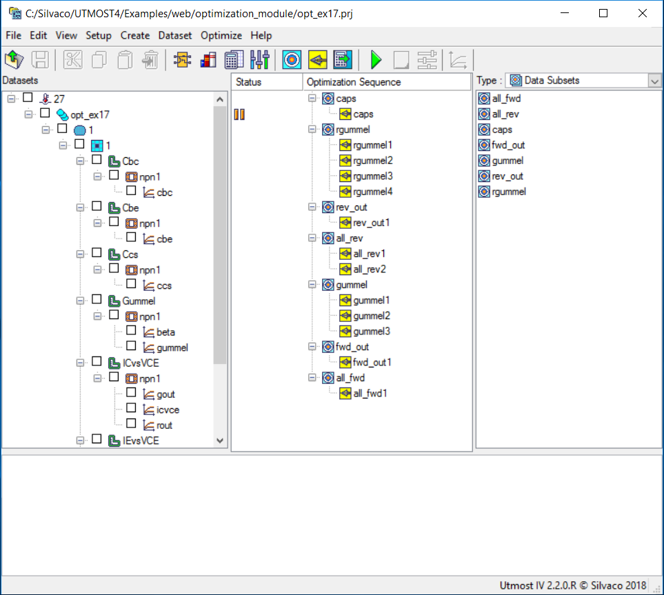
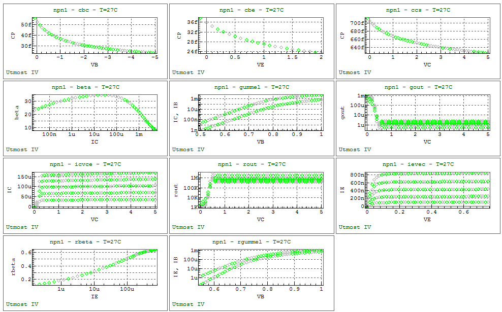
The project file opt_ex17.prj and the data file opt_ex17.uds for this example should be loaded into your database. When opened, the project will look as shown in opt_ex17_01.png and when plotted, the example measured data will look as shown in opt_ex17_02.png .
The optimization sequence, which fully automates the extraction of this Mextram bipolar model example, has seven sections. The objective of each section is to isolate a device characteristic and then to optimize only those model parameters which account for this device behavior.
The Mextram bipolar model couples the capacitance and the charge equations together. Therefore, it is important to extract the capacitance parameters first to avoid having to readjust the DC model parameters later.
The first section extracts the CJE , PE , VDE , CJC , PC , VDC , CJS , PS , VDS , and XP model parameters which describe the reverse bias capacitance characteristics of all three transistor junctions.
Once the capacitance parameters are extracted, the second section will extract the reverse Gummel parameters IS , VLR , IBR , BRI , RCV , RBV , RCC , and RBC . Then the third section will extract the reverse output characteristic parameter VER .
The fourth section is used to refine all parameters extracted in the previous two sections.
As the forward operation of the transistor is more important than the reverse, these model parameters are extracted last. In this way, the goodness of fit to the reverse data can be sacrificed if necessary to achieve the best fit to the forward data.
The fifth section extracts the parameters IS , BF , IBF , MLF , RE , IK to fit to the forward Gummel data, and the sixth section extracts the model parameter VEF to fit to the forward output characteristics.
Finally, the last section is used to refine all forward mode parameters that have been extracted in the previous two sections.
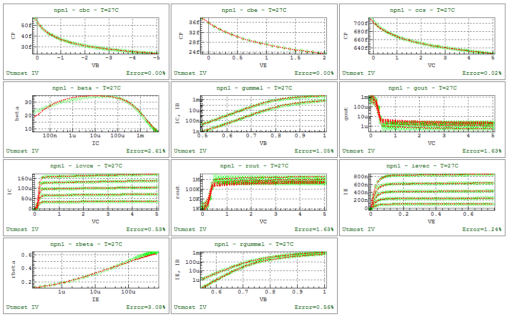
On completion of the sequence, the measured versus simulated characteristics should be as shown in opt_ex17_03.png . The model card can then be exported into an external model library file as shown in the output file opt_ex17.lib.
opt_ex17.lib
											.MODEL npn_mextram NPN (
+LEVEL    = 504            TNOM     = 27             MULT     = 1
+DTA      = 0              EXMOD    = 0              EXPHI    = 1
+EXAVL    = 0              SELFT    = 0              IS       = 8.60708e-17
+IK       = 0.00195507     VER      = 19.3323        VEF      = 32.5963
+BF       = 36.236         IBF      = 7.50703e-13    MLF      = 2.94231
+XIBI     = 0              BRI      = 0.893107       IBR      = 4.61092e-11
+VLR      = 0.536101       XEXT     = 0.63           WAVL     = 1.1e-06
+VAVL     = 3              SFH      = 0.3            RE       = 1.85427
+RBC      = 216.715        RBV      = 14.05          RCC      = 0.1
+RCV      = 0.1            SCRCV    = 1250           IHC      = 0.004
+AXI      = 0.3            CJE      = 3.58966e-14    VDE      = 0.687559
+PE       = 0.313848       XCJE     = 0              CJC      = 5.24888e-14
+VDC      = 0.554759       PC       = 0.349356       XP       = 0.00331876
+MC       = 0.5            XCJC     = 1              MTAU     = 1
+TAUE     = 2e-12          TAUB     = 4.2e-12        TEPI     = 4.1e-11
+TAUR     = 5.2e-10        XREC     = 0              AQBO     = 0.3
+AE       = 0              AB       = 1              AEPI     = 2.5
+AEX      = 0.62           AC       = 2              DVGBF    = 0.05
+DVGBR    = 0.045          VGB      = 1.17           VGC      = 1.18
+VGJ      = 1.15           DVGTE    = 0.05           AF       = 2
+KF       = 2e-11          KFN      = 2e-11          ISS      = 4.8e-17
+IKS      = 0.00025        CJS      = 7.0283e-13     VDS      = 0.57862
+PS       = 0.0509052      VGS      = 1.2            AS       = 1.58
+RTH      = 300            CTH      = 3e-09 )
opt_ex17.uds
Utmost IV CSV Data Logfile Format Version 2 Copyright (c) 1984-2018 Silvaco, Inc. All rights reserved DataSetStart DataSetName, Cbc MeasurementType, LCR BatchName, opt_ex17 WaferName, 1 DieName, 1 GroupName, 1, 0, 12000 DeviceName, npn1 Temperature, 27 FabDate, 23 Apr 2007 UserDate, 23 Apr 2007 WaferDiameter, 200 DieSize, 20, 20 NodeNames, C B E S LCRSource, B, C, 1e+06, V, 0 LCRTarget, CP Sweep, 1, V_LCR, LIN, 0.1, -5, -0.1, CALCULATED Constant, V, E, 0, 0.1, 0 Constant, V, C, 0, 0.1, 0 Constant, V, S, 0, 0.1, 0 Function, VB, VC + V_LCR Plot, cbc, XY (LIN LIN), VB, CP DataArray, CP 5.6274e-14 5.25e-14 4.95507e-14 4.71557e-14 4.51556e-14 4.34492e-14 4.19687e-14 4.06667e-14 3.95087e-14 3.8469e-14 3.75281e-14 3.66708e-14 3.58848e-14 3.51604e-14 3.44897e-14 3.38661e-14 3.32841e-14 3.27391e-14 3.22272e-14 3.17451e-14 3.12898e-14 3.08588e-14 3.04501e-14 3.00615e-14 2.96916e-14 2.93387e-14 2.90016e-14 2.8679e-14 2.83699e-14 2.80734e-14 2.77886e-14 2.75146e-14 2.72509e-14 2.69967e-14 2.67515e-14 2.65147e-14 2.62859e-14 2.60645e-14 2.58502e-14 2.56426e-14 2.54413e-14 2.5246e-14 2.50564e-14 2.48722e-14 2.46932e-14 2.4519e-14 2.43496e-14 2.41846e-14 2.40239e-14 2.38672e-14 2.37144e-14 2.35654e-14 DataSetFinish DataSetStart DataSetName, Cbe MeasurementType, LCR BatchName, opt_ex17 WaferName, 1 DieName, 1 GroupName, 1, 0, 12000 DeviceName, npn1 Temperature, 27 FabDate, 23 Apr 2007 UserDate, 23 Apr 2007 WaferDiameter, 200 DieSize, 20, 20 NodeNames, C B E S LCRSource, E, B, 1e+06, V, 0 LCRTarget, CP Sweep, 1, V_LCR, LIN, -0.1, 2, 0.1, CALCULATED Constant, V, C, 0, 0.1, 0 Constant, V, B, 0, 0.01, 0 Constant, V, S, 0, 0.1, 0 Function, VE, VB + V_LCR Plot, cbe, XY (LIN LIN), VE, CP DataArray, CP 3.77173e-14 3.59e-14 3.4401e-14 3.31335e-14 3.20411e-14 3.10853e-14 3.02387e-14 2.94809e-14 2.87968e-14 2.81746e-14 2.76051e-14 2.70809e-14 2.65961e-14 2.61456e-14 2.57255e-14 2.53323e-14 2.4963e-14 2.46154e-14 2.42871e-14 2.39764e-14 2.36818e-14 2.34017e-14 DataSetFinish DataSetStart DataSetName, Ccs MeasurementType, LCR BatchName, opt_ex17 WaferName, 1 DieName, 1 GroupName, 1, 0, 12000 DeviceName, npn1 Temperature, 27 FabDate, 23 Apr 2007 UserDate, 23 Apr 2007 WaferDiameter, 200 DieSize, 20, 20 NodeNames, C B E S LCRSource, C, S, 1e+06, V, 0 LCRTarget, CP Sweep, 1, V_LCR, LIN, -0.1, 5, 0.1, CALCULATED Constant, V, E, 0, 0.1, 0 Constant, V, B, 0, 0.01, 0 Constant, V, S, 0, 0.1, 0 Function, VC, VS + V_LCR Plot, ccs, XY (LIN LIN), VC, CP DataArray, CP 7.12799e-13 7.05e-13 6.98691e-13 6.93402e-13 6.88852e-13 6.84863e-13 6.81315e-13 6.78121e-13 6.75218e-13 6.72559e-13 6.70106e-13 6.67831e-13 6.65709e-13 6.63723e-13 6.61855e-13 6.60093e-13 6.58426e-13 6.56844e-13 6.55339e-13 6.53905e-13 6.52534e-13 6.51222e-13 6.49964e-13 6.48756e-13 6.47594e-13 6.46474e-13 6.45395e-13 6.44352e-13 6.43344e-13 6.42369e-13 6.41424e-13 6.40508e-13 6.39619e-13 6.38756e-13 6.37917e-13 6.371e-13 6.36306e-13 6.35531e-13 6.34777e-13 6.34041e-13 6.33323e-13 6.32621e-13 6.31936e-13 6.31267e-13 6.30612e-13 6.29971e-13 6.29344e-13 6.2873e-13 6.28128e-13 6.27539e-13 6.2696e-13 6.26394e-13 DataSetFinish DataSetStart DataSetName, Gummel MeasurementType, DC BatchName, opt_ex17 WaferName, 1 DieName, 1 GroupName, 1, 0, 12000 DeviceName, npn1 Temperature, 27 FabDate, 23 Apr 2007 UserDate, 23 Apr 2007 WaferDiameter, 200 DieSize, 20, 20 NodeNames, C B E S Sweep, 1, V, B, LIN, 0.5, 1, CALCULATED, 51, 0.1, 0.0 Constant, V, E, 0, 0.1, 0 Constant, V, S, 0, 0.1, 0 Constant, V, C, 2, 0.1, 0 Target, I, B Target, I, C Function, beta, IC / IB Plot, beta, XY (LOG LIN), IC, beta Plot, gummel, XY (LIN LOG), VB, IC IB DataArray, IB 9.39533e-10 1.31163e-09 1.83968e-09 2.59186e-09 3.66703e-09 5.2088e-09 7.42606e-09 1.06231e-08 1.52436e-08 2.19352e-08 3.16434e-08 4.57493e-08 6.62701e-08 9.61498e-08 1.3968e-07 2.03102e-07 2.95463e-07 4.2981e-07 6.24814e-07 9.06919e-07 1.31304e-06 1.89372e-06 2.71653e-06 3.86918e-06 5.46176e-06 7.62758e-06 1.05222e-05 1.43209e-05 1.92144e-05 2.54033e-05 3.30923e-05 4.24832e-05 5.37685e-05 6.71257e-05 8.27128e-05 0.000100665 0.000121093 0.000144082 0.000169695 0.00019797 0.000228926 0.000262564 0.000298869 0.000337815 0.000379362 0.000423465 0.000470071 0.000519121 0.000570555 0.000624308 0.000680316 DataArray, IC 2.14005e-08 3.14807e-08 4.63087e-08 6.81202e-08 1.00203e-07 1.47394e-07 2.16802e-07 3.18878e-07 4.68981e-07 6.89668e-07 1.01405e-06 1.49066e-06 2.19057e-06 3.21755e-06 4.72269e-06 6.92482e-06 1.01388e-05 1.48128e-05 2.1576e-05 3.12933e-05 4.51206e-05 6.45428e-05 9.13719e-05 0.000127674 0.000175612 0.000237223 0.000314184 0.000407631 0.000518093 0.000645515 0.000789361 0.000948728 0.00112247 0.00130929 0.00150782 0.0017167 0.00193459 0.00216021 0.00239238 0.00263 0.00287208 0.00311773 0.00336616 0.00361667 0.00386865 0.00412157 0.00437497 0.00462844 0.00488165 0.00513431 0.00538616 DataSetFinish DataSetStart DataSetName, ICvsVCE MeasurementType, DC BatchName, opt_ex17 WaferName, 1 DieName, 1 GroupName, 1, 0, 12000 DeviceName, npn1 Temperature, 27 FabDate, 23 Apr 2007 UserDate, 23 Apr 2007 WaferDiameter, 200 DieSize, 20, 20 NodeNames, C B E S Sweep, 1, V, C, LIN, 0, 5, CALCULATED, 51, 0.1, 0.0 Sweep, 2, I, B, LIN, 1e-06, CALCULATED, 1e-06, 5, 2, 0.0 Constant, V, S, 0, 0.1, 0 Constant, V, E, 0, 0.1, 0 Target, I, C Function, rout, 1 / gout Function, gout, derivative (VC, IC) Plot, gout, XY (LIN LOG), VC, gout Plot, icvce, XY (LIN LIN), VC, IC Plot, rout, XY (LIN LOG), VC, rout DataArray, IC -9.96026e-07 2.85571e-06 2.57363e-05 3.30161e-05 3.35889e-05 3.36736e-05 3.37291e-05 3.37828e-05 3.38364e-05 3.389e-05 3.39437e-05 3.39973e-05 3.40509e-05 3.41045e-05 3.41582e-05 3.42118e-05 3.42654e-05 3.4319e-05 3.43726e-05 3.44263e-05 3.44799e-05 3.45335e-05 3.45871e-05 3.46408e-05 3.46944e-05 3.4748e-05 3.48016e-05 3.48553e-05 3.49089e-05 3.49625e-05 3.50161e-05 3.50697e-05 3.51234e-05 3.5177e-05 3.52306e-05 3.52842e-05 3.53379e-05 3.53915e-05 3.54451e-05 3.54987e-05 3.55523e-05 3.5606e-05 3.56596e-05 3.57132e-05 3.57668e-05 3.58205e-05 3.58741e-05 3.59277e-05 3.59813e-05 3.6035e-05 3.60886e-05 -1.98977e-06 7.23369e-06 5.21727e-05 6.52664e-05 6.62991e-05 6.64604e-05 6.65696e-05 6.66758e-05 6.67818e-05 6.68877e-05 6.69937e-05 6.70996e-05 6.72056e-05 6.73116e-05 6.74175e-05 6.75235e-05 6.76295e-05 6.77354e-05 6.78414e-05 6.79474e-05 6.80533e-05 6.81593e-05 6.82652e-05 6.83712e-05 6.84772e-05 6.85831e-05 6.86891e-05 6.87951e-05 6.8901e-05 6.9007e-05 6.9113e-05 6.92189e-05 6.93249e-05 6.94308e-05 6.95368e-05 6.96428e-05 6.97487e-05 6.98547e-05 6.99607e-05 7.00666e-05 7.01726e-05 7.02786e-05 7.03845e-05 7.04905e-05 7.05964e-05 7.07024e-05 7.08084e-05 7.09143e-05 7.10203e-05 7.11263e-05 7.12322e-05 -2.98148e-06 1.21652e-05 7.76875e-05 9.63592e-05 9.78457e-05 9.80816e-05 9.82428e-05 9.83995e-05 9.85561e-05 9.87125e-05 9.8869e-05 9.90255e-05 9.9182e-05 9.93385e-05 9.9495e-05 9.96515e-05 9.9808e-05 9.99645e-05 0.000100121 0.000100277 0.000100434 0.00010059 0.000100747 0.000100903 0.00010106 0.000101216 0.000101373 0.000101529 0.000101686 0.000101842 0.000101999 0.000102155 0.000102312 0.000102468 0.000102625 0.000102781 0.000102938 0.000103094 0.000103251 0.000103407 0.000103564 0.00010372 0.000103877 0.000104033 0.00010419 0.000104346 0.000104503 0.000104659 0.000104816 0.000104972 0.000105129 -3.97113e-06 1.73663e-05 0.00010214 0.000126358 0.000128309 0.000128619 0.00012883 0.000129036 0.000129241 0.000129446 0.000129652 0.000129857 0.000130062 0.000130268 0.000130473 0.000130678 0.000130884 0.000131089 0.000131294 0.0001315 0.000131705 0.00013191 0.000132116 0.000132321 0.000132526 0.000132732 0.000132937 0.000133142 0.000133347 0.000133553 0.000133758 0.000133963 0.000134169 0.000134374 0.000134579 0.000134785 0.00013499 0.000135195 0.000135401 0.000135606 0.000135811 0.000136017 0.000136222 0.000136427 0.000136633 0.000136838 0.000137043 0.000137249 0.000137454 0.000137659 0.000137865 -4.95867e-06 2.26936e-05 0.000125533 0.000155346 0.00015778 0.000158163 0.000158423 0.000158676 0.000158929 0.000159181 0.000159434 0.000159687 0.000159939 0.000160192 0.000160444 0.000160697 0.00016095 0.000161202 0.000161455 0.000161707 0.00016196 0.000162212 0.000162465 0.000162718 0.00016297 0.000163223 0.000163475 0.000163728 0.000163981 0.000164233 0.000164486 0.000164738 0.000164991 0.000165243 0.000165496 0.000165749 0.000166001 0.000166254 0.000166506 0.000166759 0.000167012 0.000167264 0.000167517 0.000167769 0.000168022 0.000168274 0.000168527 0.00016878 0.000169032 0.000169285 0.000169537 DataSetFinish DataSetStart DataSetName, IEvsVCE MeasurementType, DC BatchName, opt_ex17 WaferName, 1 DieName, 1 GroupName, 1, 0, 12000 DeviceName, npn1 Temperature, 27 FabDate, 23 Apr 2007 UserDate, 23 Apr 2007 WaferDiameter, 200 DieSize, 20, 20 NodeNames, C B E S Sweep, 1, V, E, LIN, 0, 0.75, CALCULATED, 51, 0.1, 0.0 Sweep, 2, I, B, LIN, 1e-06, CALCULATED, 1e-06, 5, 2, 0.0 Constant, V, S, 0, 0.1, 0 Constant, V, C, 0, 0.1, 0 Target, I, E Plot, ievec, XY (LIN LIN), VE, IE DataArray, IE -3.97448e-09 3.99618e-08 6.47407e-08 7.87161e-08 8.66105e-08 9.10848e-08 9.36362e-08 9.51063e-08 9.59682e-08 9.64875e-08 9.68139e-08 9.70314e-08 9.71874e-08 9.73086e-08 9.741e-08 9.75001e-08 9.75838e-08 9.76639e-08 9.77418e-08 9.78185e-08 9.78945e-08 9.79701e-08 9.80454e-08 9.81206e-08 9.81957e-08 9.82707e-08 9.83457e-08 9.84207e-08 9.84957e-08 9.85706e-08 9.86456e-08 9.87205e-08 9.87955e-08 9.88704e-08 9.89454e-08 9.90203e-08 9.90953e-08 9.91702e-08 9.92451e-08 9.93201e-08 9.9395e-08 9.947e-08 9.95449e-08 9.96198e-08 9.96948e-08 9.97697e-08 9.98447e-08 9.99196e-08 9.99946e-08 1.00069e-07 1.00144e-07 -1.02257e-08 1.00895e-07 1.63602e-07 1.98969e-07 2.18939e-07 2.3025e-07 2.36694e-07 2.40402e-07 2.42573e-07 2.43879e-07 2.44699e-07 2.45245e-07 2.45637e-07 2.45941e-07 2.46196e-07 2.46423e-07 2.46634e-07 2.46836e-07 2.47033e-07 2.47227e-07 2.47419e-07 2.4761e-07 2.47801e-07 2.47991e-07 2.48181e-07 2.48371e-07 2.48561e-07 2.4875e-07 2.4894e-07 2.4913e-07 2.4932e-07 2.49509e-07 2.49699e-07 2.49889e-07 2.50079e-07 2.50268e-07 2.50458e-07 2.50648e-07 2.50837e-07 2.51027e-07 2.51217e-07 2.51407e-07 2.51596e-07 2.51786e-07 2.51976e-07 2.52165e-07 2.52355e-07 2.52545e-07 2.52735e-07 2.52924e-07 2.53114e-07 -1.85209e-08 1.72496e-07 2.80375e-07 3.41238e-07 3.75603e-07 3.95062e-07 4.06143e-07 4.12516e-07 4.16245e-07 4.18487e-07 4.19893e-07 4.20829e-07 4.21499e-07 4.2202e-07 4.22457e-07 4.22846e-07 4.23208e-07 4.23555e-07 4.23893e-07 4.24225e-07 4.24555e-07 4.24883e-07 4.25211e-07 4.25537e-07 4.25864e-07 4.2619e-07 4.26516e-07 4.26842e-07 4.27168e-07 4.27494e-07 4.2782e-07 4.28145e-07 4.28471e-07 4.28797e-07 4.29123e-07 4.29449e-07 4.29775e-07 4.301e-07 4.30426e-07 4.30752e-07 4.31078e-07 4.31404e-07 4.3173e-07 4.32056e-07 4.32381e-07 4.32707e-07 4.33033e-07 4.33359e-07 4.33685e-07 4.34011e-07 4.34336e-07 -2.88726e-08 2.51567e-07 4.10083e-07 4.9955e-07 5.50071e-07 5.78675e-07 5.9496e-07 6.04324e-07 6.09799e-07 6.13089e-07 6.15151e-07 6.16523e-07 6.17505e-07 6.18268e-07 6.18908e-07 6.19478e-07 6.20008e-07 6.20516e-07 6.21011e-07 6.21498e-07 6.21982e-07 6.22463e-07 6.22943e-07 6.23422e-07 6.239e-07 6.24378e-07 6.24856e-07 6.25334e-07 6.25812e-07 6.26289e-07 6.26767e-07 6.27245e-07 6.27723e-07 6.282e-07 6.28678e-07 6.29156e-07 6.29633e-07 6.30111e-07 6.30589e-07 6.31066e-07 6.31544e-07 6.32022e-07 6.32499e-07 6.32977e-07 6.33455e-07 6.33932e-07 6.3441e-07 6.34888e-07 6.35365e-07 6.35843e-07 6.36321e-07 -4.13292e-08 3.36352e-07 5.50027e-07 6.70678e-07 7.3882e-07 7.77401e-07 7.99362e-07 8.11987e-07 8.19365e-07 8.23798e-07 8.26574e-07 8.28419e-07 8.2974e-07 8.30766e-07 8.31626e-07 8.32391e-07 8.33104e-07 8.33786e-07 8.34452e-07 8.35107e-07 8.35757e-07 8.36404e-07 8.37049e-07 8.37692e-07 8.38335e-07 8.38978e-07 8.39621e-07 8.40263e-07 8.40905e-07 8.41548e-07 8.4219e-07 8.42832e-07 8.43474e-07 8.44117e-07 8.44759e-07 8.45401e-07 8.46043e-07 8.46685e-07 8.47328e-07 8.4797e-07 8.48612e-07 8.49254e-07 8.49896e-07 8.50538e-07 8.51181e-07 8.51823e-07 8.52465e-07 8.53107e-07 8.53749e-07 8.54392e-07 8.55034e-07 DataSetFinish DataSetStart DataSetName, RGummel MeasurementType, DC BatchName, opt_ex17 WaferName, 1 DieName, 1 GroupName, 1, 0, 12000 DeviceName, npn1 Temperature, 27 FabDate, 23 Apr 2007 UserDate, 23 Apr 2007 WaferDiameter, 200 DieSize, 20, 20 NodeNames, C B E S Sweep, 1, V, B, LIN, 0.55, 1, CALCULATED, 51, 0.1, 0.0 Constant, V, E, 2, 0.1, 0 Constant, V, S, 0, 0.1, 0 Constant, V, C, 0, 0.1, 0 Target, I, B Target, I, E Function, rbeta, IE / IB Plot, rbeta, XY (LOG LIN), IE, rbeta Plot, rgummel, XY (LIN LOG), VB, IE IB DataArray, IB 1.32684e-06 1.71508e-06 2.21616e-06 2.86211e-06 3.69351e-06 4.76135e-06 6.1291e-06 7.87485e-06 1.00931e-05 1.28963e-05 1.64144e-05 2.07937e-05 2.61927e-05 3.27747e-05 4.06992e-05 5.01107e-05 6.11279e-05 7.38355e-05 8.82786e-05 0.000104463 0.000122358 0.000141905 0.000163022 0.000185615 0.000209582 0.000234821 0.000261233 0.000288723 0.000317203 0.000346593 0.000376821 0.00040782 0.000439533 0.000471906 0.000504894 0.000538453 0.000572547 0.000607143 0.00064221 0.000677721 0.000713653 0.000749984 0.000786693 0.000823763 0.000861178 0.000898923 0.000936983 0.000975348 0.001014 0.00105294 0.00109215 DataArray, IE 1.55404e-07 2.19037e-07 3.08369e-07 4.33501e-07 6.08295e-07 8.51629e-07 1.18894e-06 1.65411e-06 2.2915e-06 3.15819e-06 4.32583e-06 5.88187e-06 7.92936e-06 1.05849e-05 1.39742e-05 1.8225e-05 2.34591e-05 2.97834e-05 3.72823e-05 4.60131e-05 5.6004e-05 6.72554e-05 7.97433e-05 9.34245e-05 0.000108242 0.000124128 0.00014101 0.000158816 0.00017747 0.000196902 0.000217044 0.000237832 0.000259205 0.000281109 0.000303492 0.000326309 0.000349515 0.000373072 0.000396944 0.000421098 0.000445505 0.000470137 0.000494969 0.00051998 0.000545148 0.000570454 0.000595882 0.000621415 0.000647038 0.00067274 0.000698506 DataSetFinish