opt_ex01 : Model Generation Using Parameter Optimization
Requires: Utmost IV, SmartSpice, SmartView
Minimum Versions: Utmost IV 1.10.6.R, SmartSpice 4.10.2.R, SmartView 2.28.2.R
This example shows how to use model parameter optimization to extract a mosfet SPICE model.
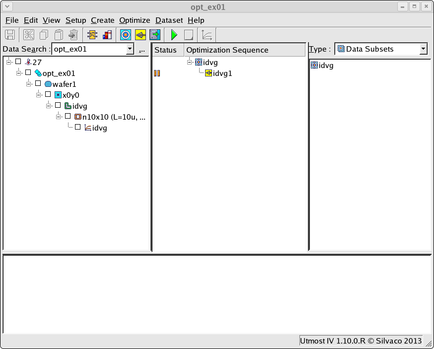
The project file opt_ex01.prj and the data file opt_ex01.uds for this example should both be loaded into your database. When opened, the project will look as shown in opt_ex01_01.png .
A SPICE model is a mathematical representation of an electrical or electronic device which can be used to predict how this device will behave in a circuit. In order to develop the SPICE model, measured data from this device is used and the parameters of the SPICE model are adjusted until the simulated and measured data are in good agreement.
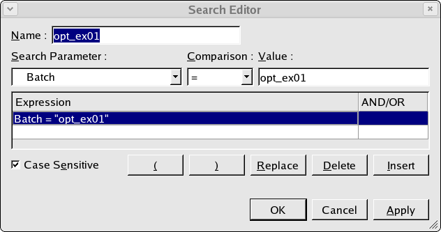
The measured data or datasets are already stored in the database and to retrieve this data we perform a search which is shown in opt_ex01_02.png . In this simple search we are retrieving any data with the batch name 'opt_ex01' and for the example this will retrieve a single dataset from the database.
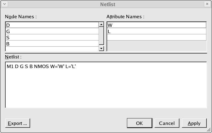
In addition to the search, the retrieved datasets must also match to the device netlist which is defined as shown in opt_ex01_03.png . If the datasets do not match to the device nodes and device attributes as defined in the netlist they will not be retrieved.
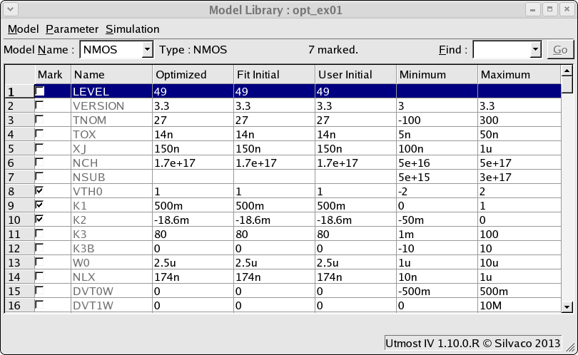
The device netlist also defines the model which is to be generated, in this case a compact mosfet model called 'NMOS'. A SPICE model which matches to this must be defined. Selecting the Setup->Model Library menu item will open up the model library window as show in opt_ex01_04.png . A single BSIM3 MOSFET model has been added to the model library with the name 'NMOS'in order to match the model name which was defined in the device simulation netlist.
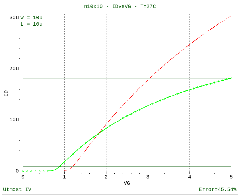
At this point, with the dataset available and the netlist and model card defined, a simulation can be performed which will compare the measured and simulated data as shown in opt_ex01_05.png .
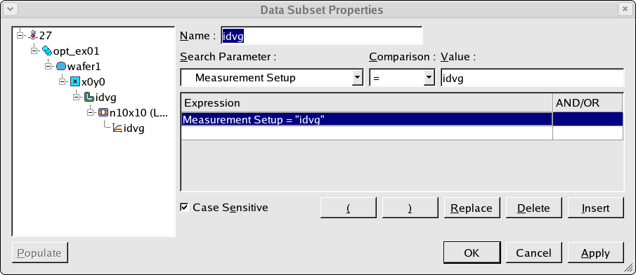
To automate the generation of the SPICE model, we need to select the dataset and add it to the optimization sequence. This is done by creating a data subset as shown in opt_ex01_06.png . In this data subset, datasets with a measurement setup named 'idvg' are selected which gives a single dataset in this case.
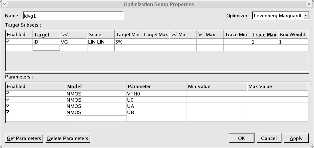
Once the data subset has been defined and added into the optimization sequence, we need to define the optimization that is to be performed. This is done by creating an optimization setup as shown in opt_ex01_07.png . The optimization setup has two sections. In the first section, the data targets which are to be used in the optimization are defined. In the second section, the SPICE parameters which are to be optimized are given.
Once the optimization setup has been defined, this can be added into the optimization sequence as the child of the data subset. When the optimization sequence is run, the model parameters are adjusted to reduce the error in the measured data which matches to the data targets which were defined.
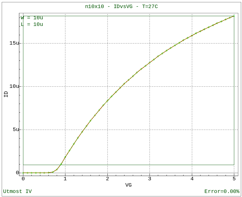
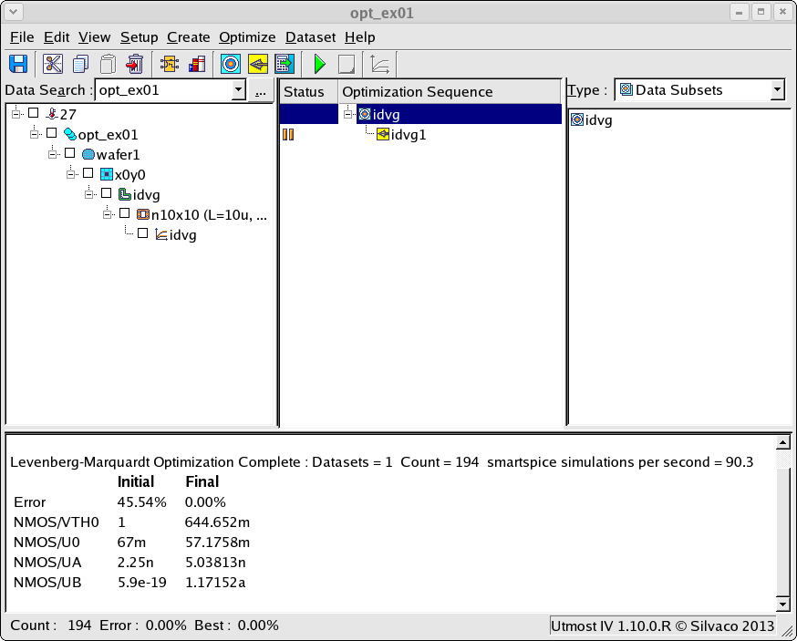
After the optimization has finished, the final measured versus simulated data will be displayed as shown in opt_ex01_08.png . In addition, the results of the SPICE model parameter optimization are displayed in the project window as shown in opt_ex01_09.png and are also written into the model library of the project.
The generated SPICE model can then be saved to the database with the project or exported into an external file.
opt_ex01.lib
											.MODEL NMOS NMOS (
+LEVEL    = 49             VERSION  = 3.3            TNOM     = 27
+TOX      = 1.4e-08        XJ       = 1.5e-07        NCH      = 1.7e+17
+VTH0     = 0.65           K1       = 0.34           K2       = -0.05
+K3       = 80             K3B      = 0              W0       = 2.5e-06
+NLX      = 1.74e-07       DVT0W    = 0              DVT1W    = 0
+DVT2W    = -0.032         DVT0     = 2.2            DVT1     = 0.53
+DVT2     = -0.032         U0       = 0.057          UA       = 5e-09
+UB       = 1.2e-18        UC       = -7.7e-11       VSAT     = 80000
+A0       = 1              AGS      = 0              B0       = 0
+B1       = 0              KETA     = -0.047         A1       = 0
+A2       = 1              RDSW     = 0              PRWG     = 0
+PRWB     = 0              WR       = 1              WINT     = 0
+LINT     = 0              XL       = 0              XW       = 0
+DWG      = 0              DWB      = 0              VOFF     = -0.1
+NFACTOR  = 1              CIT      = 0              CDSC     = 0.00024
+CDSCD    = 0              CDSCB    = 0              ETA0     = 0.08
+ETAB     = -0.07          DSUB     = 0.56           PCLM     = 1.3
+PDIBLC1  = 0.39           PDIBLC2  = 0.0086         PDIBLCB  = 0
+DROUT    = 0.56           PSCBE1   = 4.2e+08        PSCBE2   = 5e-05
+PVAG     = 0              DELTA    = 0.01           MOBMOD   = 1
+PRT      = 0              UTE      = -1.5           KT1      = 0
+KT1L     = 0              KT2      = 0              UA1      = 4.3e-09
+UB1      = -7.6e-18       UC1      = -5.6e-11       AT       = 33000
+NQSMOD   = 0              WL       = 0              WLN      = 1
+WW       = 0              WWN      = 1              WWL      = 0
+LL       = 0              LLN      = 1              LW       = 0
+LWN      = 1              LWL      = 0              CAPMOD   = 2
+TPB      = 0              TPBSW    = 0              TPBSWG   = 0
+TCJ      = 0              TCJSW    = 0              TCJSWG   = 0
+NOFF     = 1              ACDE     = 1              MOIN     = 15 )
opt_ex01.uds
											Utmost IV CSV Data Logfile
Format Version 1
Copyright (c) 1984-2016 Silvaco, Inc. All rights reserved


DataSetStart

DataSetName, idvg
MeasurementType, DC

BatchName, opt_ex01
WaferName, wafer1
DieName, x0y0
DeviceName, n10x10
Temperature, 27

FabDate, 18 Jan 2013
UserDate, 18 Jan 2013

WaferDiameter, 0.2
DieLayout, FOUR_CROSSING
DieSize, 0.02, 0.02

Attribute, L, 1e-05
Attribute, W, 1e-05

NodeNames, d g s b

Sweep, 1, V, G, LIN, 0, 5, 0.1, CALCULATED, 0.1, 0

Sweep, 2, V, B, LIN, 0, -3, -0.6, CALCULATED, 0.1, 0

Constant, V, D, 0.1, 0.1, 0
Constant, V, S, 0, 0.1, 0

Target, I, D

Plot, idvg, XY (LIN LIN), VG, ID

DataArray, ID
3.23473e-15    4.08074e-14    5.13954e-13    6.4346e-12     7.89344e-11
9.08944e-10    9.03532e-09    7.2565e-08     3.8348e-07     1.03755e-06
1.81487e-06    2.59298e-06    3.34429e-06    4.0654e-06     4.75713e-06
5.42082e-06    6.05777e-06    6.66926e-06    7.25653e-06    7.82077e-06
8.36313e-06    8.88467e-06    9.38645e-06    9.86941e-06    1.03345e-05
1.07825e-05    1.12143e-05    1.16306e-05    1.20322e-05    1.24197e-05
1.27937e-05    1.31549e-05    1.35038e-05    1.3841e-05     1.41669e-05
1.44821e-05    1.47869e-05    1.50819e-05    1.53673e-05    1.56436e-05
1.59112e-05    1.61704e-05    1.64215e-05    1.66648e-05    1.69007e-05
1.71293e-05    1.73511e-05    1.75661e-05    1.77748e-05    1.79772e-05
1.81737e-05    1.31599e-16    2.0663e-15     3.26007e-14    5.13449e-13
8.02039e-12    1.21436e-10    1.65832e-09    1.7986e-08     1.40105e-07
5.87548e-07    1.29074e-06    2.04743e-06    2.79071e-06    3.50764e-06
4.19673e-06    4.85862e-06    5.49431e-06    6.10494e-06    6.69166e-06
7.25561e-06    7.7979e-06     8.31958e-06    8.82165e-06    9.30507e-06
9.77073e-06    1.02195e-05    1.06521e-05    1.10694e-05    1.1472e-05
1.18606e-05    1.22358e-05    1.25983e-05    1.29485e-05    1.32871e-05
1.36145e-05    1.39311e-05    1.42375e-05    1.4534e-05     1.4821e-05
1.5099e-05     1.53682e-05    1.56291e-05    1.58819e-05    1.61269e-05
1.63646e-05    1.6595e-05     1.68185e-05    1.70354e-05    1.72458e-05
1.745e-05      1.76483e-05    1.48656e-17    2.4411e-16     4.37516e-15
7.87456e-14    1.41213e-12    2.49143e-11    4.12658e-10    5.6486e-09
5.56083e-08    3.30926e-07    9.38352e-07    1.66792e-06    2.40236e-06
3.11484e-06    3.8009e-06     4.46041e-06    5.09416e-06    5.70315e-06
6.28848e-06    6.85125e-06    7.39252e-06    7.91335e-06    8.41471e-06
8.89754e-06    9.36273e-06    9.81112e-06    1.02435e-05    1.06606e-05
1.10631e-05    1.14517e-05    1.1827e-05     1.21896e-05    1.254e-05
1.28788e-05    1.32065e-05    1.35235e-05    1.38302e-05    1.41272e-05
1.44147e-05    1.46932e-05    1.4963e-05     1.52244e-05    1.54779e-05
1.57236e-05    1.59619e-05    1.6193e-05     1.64172e-05    1.66348e-05
1.6846e-05     1.70511e-05    1.72501e-05    0              4.80061e-17
9.10037e-16    1.79156e-14    3.52646e-13    6.87739e-12    1.28932e-10
2.0971e-09     2.4787e-08     1.88054e-07    6.88998e-07    1.38452e-06
2.10878e-06    2.81653e-06    3.49932e-06    4.15619e-06    4.78764e-06
5.3946e-06     5.97809e-06    6.53919e-06    7.07895e-06    7.59839e-06
8.09849e-06    8.58017e-06    9.04431e-06    9.49174e-06    9.92324e-06
1.03395e-05    1.07414e-05    1.11293e-05    1.15041e-05    1.18661e-05
1.22161e-05    1.25546e-05    1.28819e-05    1.31986e-05    1.35051e-05
1.38019e-05    1.40893e-05    1.43677e-05    1.46374e-05    1.48988e-05
1.51523e-05    1.5398e-05     1.56364e-05    1.58676e-05    1.6092e-05
1.63098e-05    1.65212e-05    1.67264e-05    1.69257e-05    0
1.45868e-17    2.55802e-16    5.34961e-15    1.12774e-13    2.36459e-12
4.83093e-11    8.89558e-10    1.22815e-08    1.10546e-07    5.10019e-07
1.16537e-06    1.87808e-06    2.58084e-06    3.26025e-06    3.91431e-06
4.54328e-06    5.14796e-06    5.72935e-06    6.2885e-06     6.82643e-06
7.34416e-06    7.84266e-06    8.32283e-06    8.78556e-06    9.23167e-06
9.66192e-06    1.00771e-05    1.04778e-05    1.08647e-05    1.12385e-05
1.15997e-05    1.19488e-05    1.22865e-05    1.26131e-05    1.29291e-05
1.3235e-05     1.35312e-05    1.38181e-05    1.4096e-05     1.43652e-05
1.46263e-05    1.48793e-05    1.51247e-05    1.53628e-05    1.55938e-05
1.58179e-05    1.60354e-05    1.62466e-05    1.64517e-05    1.66509e-05
0              0              9.08738e-17    1.95629e-15    4.34758e-14
9.63869e-13    2.09892e-11    4.23098e-10    6.64902e-09    6.8293e-08
3.8165e-07     9.92743e-07    1.69264e-06    2.39023e-06    3.06621e-06
3.71738e-06    4.34374e-06    4.946e-06      5.52513e-06    6.08214e-06
6.61804e-06    7.13385e-06    7.63051e-06    8.10894e-06    8.57001e-06
9.01454e-06    9.4433e-06     9.85701e-06    1.02564e-05    1.0642e-05
1.10146e-05    1.13746e-05    1.17226e-05    1.20592e-05    1.23848e-05
1.26999e-05    1.30049e-05    1.33002e-05    1.35863e-05    1.38634e-05
1.4132e-05     1.43923e-05    1.46447e-05    1.48895e-05    1.5127e-05
1.53574e-05    1.5581e-05     1.57981e-05    1.60089e-05    1.62135e-05
1.64123e-05

DataSetFinish