019_jitter_sim : Jitter analysis
Requires: SmartSpice & Smartview
Minimum Versions: SMARTSPICE 4.18.16.R
The benefits of this example are that the user can perform further analysis on saved results without having to re-execute a lengthy simulation. The example demonstrates this by performing Timing Jitter analysis on a previously executed simulation run.
Referring to the schematic, a transient analysis is performed by sourcing and running a simulation on the main "ex1_long.in" inputdeck. The voltage waveforms at node 3 and 4 are saved in the "ex1_long.raw" simulation results file captured during the transient analysis.
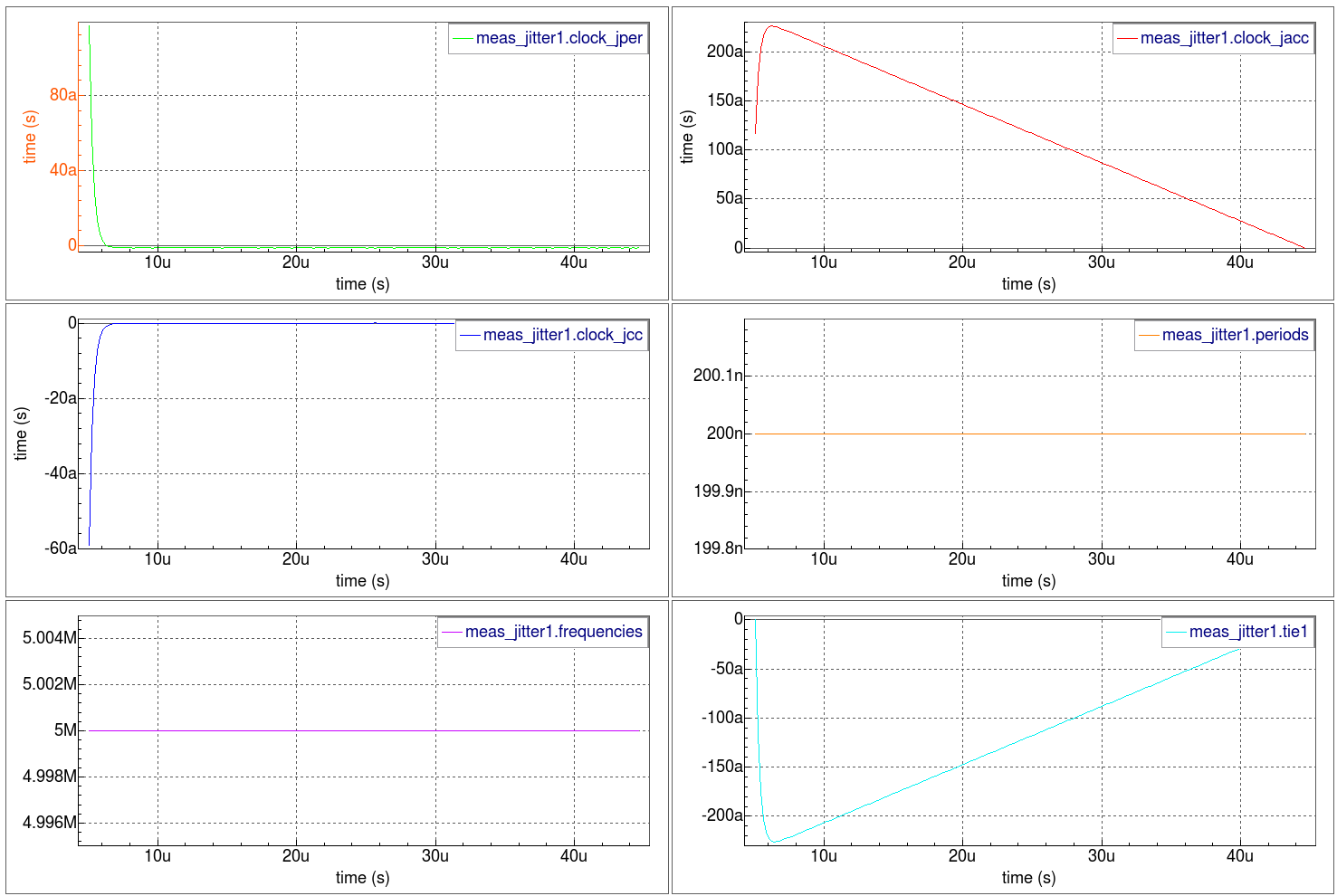
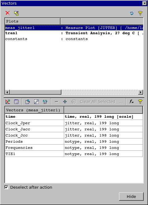
Separately, the "Clock_jitter_meas.in" controldeck is sourced. The control section loads the "ex1_long.raw" simulation results file and performs a Timing Jitter calculation on the voltage information collected at node 3 during the previous simulation run. Furthermore, all Timing Jitter analysis jitter vectors are also generated (the .MEASURE ... JITTER statement).
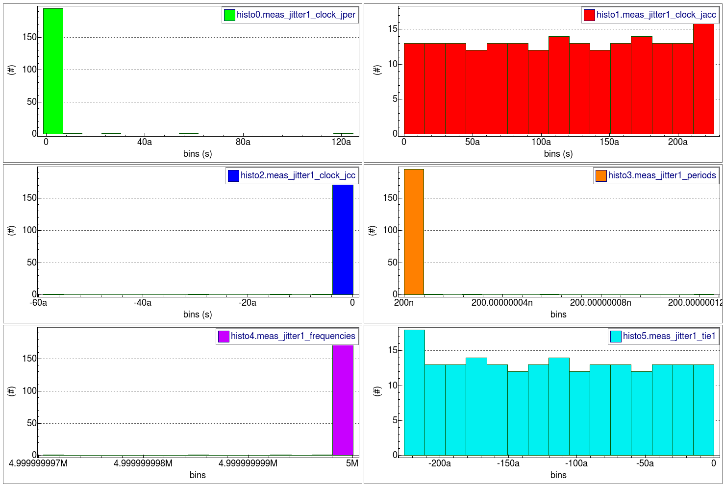
The waveforms show all Timing Jitter analysis metrics versus time at node 3. The histograms show all Timing Jitter analysis distributions at node 3.
ex1_long.in
											*  Bipolar: Long-Tail pair
***********************************

VIN  1 0  DC 0  SIN(0 0.1 5MEG)  AC 1
VCC  8 0  DC 10
VEE  9 0  DC -12
RS1  1 2  1K
RS2  5 0  1K
RC1  3 8  10K
RC2  4 8  10K
RBIAS  7 8  20K
CLOAD  3 4  5PF
Q1  3 2 6  QNL
Q2  4 5 6  QNL
Q3  6 7 9  QNL
Q4  7 7 9  QNL

.MODEL QNL NPN(BF=80 RB=100 CCS=2PF TF=0.3NS TR=6NS CJE=3PF CJC=2PF VA=50)
*
**.OPTION MEASRAW=0 post keepopinfo
**.OP current 20ns
.TRAN 5NS 50000NS
.save v(3) v(4)
*
.OPTIONS ACCT=2 RELTOL=0.001 NOMOD  post rawpts=300
.END
Clock_Jitter_meas.in
											* Timing Jitter measurement
*

.control
    load ex1_long.raw
    measure Clock jitter V(3) FROM=5u TO=45u fall='1' VAL=3.8 TARG=V(3) fall='200' VAL=3.8

.endc

.end
019_jitter_sim
[an error occurred while processing this directive]


