005 : Logic Gate Recognition
Minimum Required Version: Guardian LVS 4.8.36.R
Guardian LVS recognizes primitive logic gates before the netlist comparison. It recognizes not only simple logic gates such as NAND, NOR, and INV, but also complex gates such as AOI and OAI. It allows those logic gates with multiple terminals, such as NAND2, NAND3, NAND4, and so on.
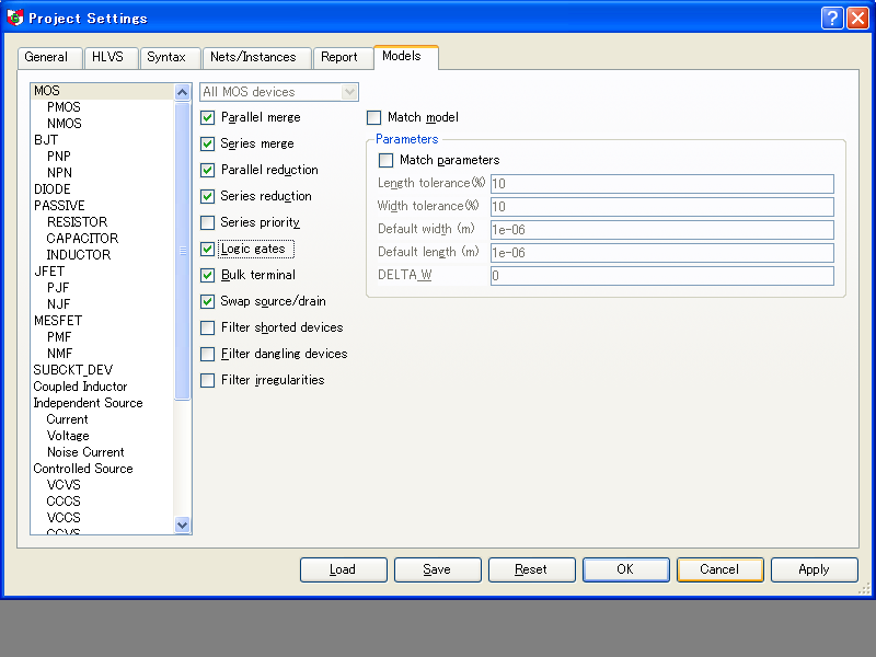
To use this feature, a check box Logic gates in the Models page of the Project Settings dialog should be checked. And also, the net names for power and ground should be specified in Nets/Instances page in the same dialog.
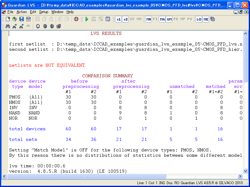
Guardian LVS reports to its log file how many logic gates are found in the specified netlists for the comparison. Those logic gates are treated like other primitive devices in the SPICE netlist format. See an example of the log file with logic gate recognition in CMOS_PFD_lvs.log.
In this report, it is easier to find that a NOR gate existing in the second (layout) netlist doesn't exist in the first (schematic) one, and to guess that one of the NAND gates may be replaced with this NOR gate.
The actual operation steps required to check the command behaviors are as follows:
1) Start Guardian LVS in the GUI mode.
2) Run the Setup->Project Settings command to show the Project Settings dialog.
3) Click the Reset button in the Project Settings dialog.
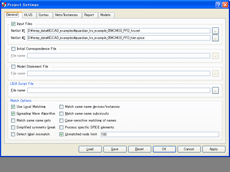
4) Select the check box Input Files in the General page, and set the following netlists as #1 and #2 netlists:
#1 : CMOS_PFD_lvs.net (schematic netlist)
#2 : CMOS_PFD_hier.spice (layout netlist)
(see lvs_example_05_1.png ).
5) Click the OK button in the Project Settings dialog.
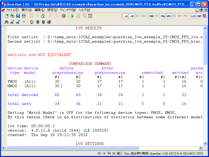
6) Select Action->Run Lvs in the Guardian LVS menu bar. The netlist comparison will be executed, and the resultant log file will appear in the Guardian LVS window. In the log file, only primitive devices will be listed (see lvs_example_05_2.png ).
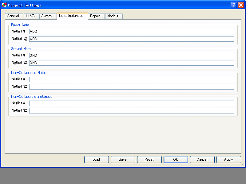
7) Run the Setup->Project Settings command again, and open the Nets/Instances page (see lvs_example_05_3.png ).
8) Set VDD as a power net and GND as a ground net for the both input netlists.
9) Open the Models page in the same dialog, and click Logic gates for MOS devices (see lvs_example_05_4.png ).
10) Close the Project Settings dialog with the OK button, and run LVS again. The new log file will appear in the Guardian LVS window, in which some logic gates are found for the netlist comparison (see lvs_example_05_5.png ).
CMOS_PFD_lvs.log
											                             LVS RESULTS

First netlist  : D:\guardian_example_05\CMOS_PFD_lvs.net
Second netlist : D:\guardian_example_05\CMOS_PFD_hier.spice


netlists are NOT EQUIVALENT

                          COMPARISON SUMMARY
device device         before            after                                 parameter
 type  model       preprocessing     preprocessing       unmatched    matched   error
                    #1       #2       #1       #2       #1       #2    #1=#2    #1=#2
PMOS   (All)        30       30        0        0        0        0        0      OFF
NMOS   (All)        30       30        0        0        0        0        0      OFF
INV    INV           0        0        8        8        0        0        8      OFF
NAND   NAND          0        0        9        8        1        0        8      OFF
NOR    NOR           0        0        0        1        0        1        0      OFF

total devices       60       60       17       17        1        1       16        0

total nets          34       36       21       21        5        5       16

Setting "Match Model" is OFF for the following device types: PMOS, NMOS.
By this reason there is no distributions of statistics between some different models for mentioned device types.

lvs time: 00:00:00.6
version:  4.8.5.R (build 1630) (LE 100519)
created:  Tue Oct 12 10:28:06 2010

                             LVS SETTINGS

Guardian message file           : D:\guardian_example_05\CMOS_PFD_lvs#lvs\CMOS_PFD_lvs.mes
Guardian filtered nodes file    : D:\guardian_example_05\CMOS_PFD_lvs#lvs\CMOS_PFD_lvs.flt
Guardian merged devices file    : D:\guardian_example_05\CMOS_PFD_lvs#lvs\CMOS_PFD_lvs.mrg
Guardian matched nodes file     : D:\guardian_example_05\CMOS_PFD_lvs#lvs\CMOS_PFD_lvs.mtc
Guardian unmatched nodes file   : D:\guardian_example_05\CMOS_PFD_lvs#lvs\CMOS_PFD_lvs.unm
Guardian parameter error file   : D:\guardian_example_05\CMOS_PFD_lvs#lvs\CMOS_PFD_lvs.par
Guardian parameter match file   : D:\guardian_example_05\CMOS_PFD_lvs#lvs\CMOS_PFD_lvs.pma
Guardian port swappability file : D:\guardian_example_05\CMOS_PFD_lvs#lvs\CMOS_PFD_lvs.psw

General Settings:

Use Local Matching on
Spreading Wave Algorithm on
Match same name nets off
Match same name devices/instances off
Match same name subcircuits off
Case-sensitive matching of names off
Simplified symmetry break off
Detect label mismatch off
Process specific SPICE elements off
Unmatched node limit: 100

HLVS Settings:

Hierarchical mode off
Equalize hierarchy of compared subcircuits on
Stop when first non-equivalent subcircuit pair is detected on
Combine high-shorted ports of subcircuits off
Detect floating ports of subcircuits off
Exclude parameterized subcircuits off
Resolve ambiguities for ports off
Use same port names off
Use swappability of port groups off

Syntax Settings:

Duplicated Subcircuit: ignore subcircuit
End-of-line comment characters: ;
Remove net name suffix starting from colon(:) off
Keep multiplier factor of devices off
Allow floating pins in subcircuit calls off
All subcircuit ports non-collapsible off
Collapsible nets: "All nets"

Report Settings:

Write match file on
Write merge file on
Write message file on
Write parameter match file on
Write filter file on
Write port swappability file on
Report LW parameters in microns on
Report guess statistics on
CMOS_PFD_lvs.net
											* Gateway 2.12.0.A Guardian Netlist Generator
* Workspace name:       D:\temp_data\Product_test\simucad-analog-demo\1.0.1.R\gateway\SBCD_kuwa_2.work_space.workspace
* Simulation name:      D:\temp_data\Product_test\simucad-analog-demo\1.0.1.R\gateway\CMOS_PFD.schlr
* Simulation timestamp: 29-9-2010 17:06:21

* Schematic name: CMOS_PFD
.SUBCKT CMOS_PFD data dclock Down Reset Up
X1 data NET1 INV
X2 NET5 NET1 NET2 NAND2
X3 NET2 NET15 NET6 NAND2
X4 NET6 Reset NET15 NAND2
X5 Reset NET13 NET16 NAND2
X6 NET16 NET9 NET13 NAND2
X7 NET8 NET7 NET9 NAND2
X8 dclock NET8 INV
X9 NET2 NET3 INV
X10 NET3 NET4 INV
X11 NET9 NET10 INV
X12 NET10 NET11 INV
X13 NET4 NET6 Reset NET5 NAND3
X14 Reset NET13 NET11 NET7 NAND3
X15 NET6 NET2 NET9 NET13 Reset NAND4
X16 NET5 Up INV
X17 NET7 Down INV
.ENDS CMOS_PFD

* Schematic name: NAND2
.SUBCKT NAND2 A B Y
M1 Y A VDD VDD CMOSP L=2U W=20U M=1
M2 Y B VDD VDD CMOSP L=2U W=20U M=1
M3 Y A NET2 GND CMOSN L=2U W=10U M=1
M4 NET2 B GND GND CMOSN L=2U W=10U M=1
.ENDS NAND2

* Schematic name: NAND3
.SUBCKT NAND3 A B C Y
M1 Y A VDD VDD CMOSP L=2U W=5U M=1
M2 Y B VDD VDD CMOSP L=2U W=5U M=1
M3 NET3 B NET2 GND CMOSN L=2U W=5U M=1
M4 NET2 C GND GND CMOSN L=2U W=5U M=1
M5 Y A NET3 GND CMOSN L=2U W=5U M=1
M6 Y C VDD VDD CMOSP L=2U W=5U M=1
.ENDS NAND3

* Schematic name: NAND4
.SUBCKT NAND4 A B C D Y
M1 Y A VDD VDD CMOSP L=2U W=5U M=1
M2 Y B VDD VDD CMOSP L=2U W=5U M=1
M3 NET3 B NET2 GND CMOSN L=2U W=5U M=1
M4 NET2 C NET5 GND CMOSN L=2U W=5U M=1
M5 Y A NET3 GND CMOSN L=2U W=5U M=1
M6 Y C VDD VDD CMOSP L=2U W=5U M=1
M7 Y D VDD VDD CMOSP L=2U W=5U M=1
M8 NET5 D GND GND CMOSN L=2U W=5U M=1
.ENDS NAND4

* Schematic name: INV
.SUBCKT INV IN1 OUT1
M1 OUT1 IN1 VDD VDD CMOSP L=2U W=5U M=1
M2 OUT1 IN1 GND GND CMOSN L=2U W=5U M=1
.ENDS INV

* Global Nodes Declarations
.GLOBAL GND VDD

* End of the netlist
CMOS_PFD_hier.spice
											*******************************************************************************
*
* Extracted SPICE netlist for top cell CMOS_PFD
* Created Wed Sep 29 18:12:42 2010 by hipex 3.4.6.R (Mon May 03, 2010 9:00 PDT) version
*
*******************************************************************************


.GLOBAL VDD GND
.MODEL P1P2 C
.MODEL HVCMOSN NMOS
.MODEL HVCMOSP PMOS
.MODEL NPN NPN
.MODEL RNPOLY R
.MODEL RPPLUS R
.MODEL RNWELL R
.MODEL CMOSP PMOS
.MODEL PNP PNP
.MODEL CMOSN NMOS
.MODEL RPOLY R

*.SUBCKT_DEV  IND X 2


*******************************************************************************
*
* Sub-Circuit Netlist of : CMOS_PFD
*
*******************************************************************************

.subckt CMOS_PFD GND VDD
MI14 VDD #10 #7 VDD CMOSP  L=2U W=20U AS=60P AD=110P PS=26U PD=51U
MI30 #22 #8 #6 GND CMOSN  L=2U W=10U AS=55P AD=30P PS=31U PD=16U
MI46 #25 #6 #10 GND CMOSN  L=2U W=10U AS=55P AD=30P PS=31U PD=16U
MI54 #30 #10 #12 GND CMOSN  L=2U W=10U AS=55P AD=30P PS=31U PD=16U
MI56 #5 #13 GND GND CMOSN  L=2U W=10U AS=55P AD=55P PS=31U PD=31U
MI58 #13 #2 GND GND CMOSN  L=2U W=10U AS=55P AD=30P PS=31U PD=16U
MI59 #2 #32 GND GND CMOSN  L=2U W=10U AS=55P AD=55P PS=31U PD=31U
MI57 GND #12 #13 GND CMOSN  L=2U W=10U AS=30P AD=55P PS=16U PD=31U
MI55 #14 #5 GND GND CMOSN  L=2U W=10U AS=55P AD=55P PS=31U PD=31U
MI50 #28 #7 #11 GND CMOSN  L=2U W=10U AS=55P AD=30P PS=31U PD=16U
MI52 GND #14 #29 GND CMOSN  L=2U W=10U AS=30P AD=55P PS=16U PD=31U
MI53 #29 #11 #30 GND CMOSN  L=2U W=10U AS=30P AD=30P PS=16U PD=16U
MI51 #17 #12 GND GND CMOSN  L=2U W=10U AS=55P AD=55P PS=31U PD=31U
MI48 #27 #10 #7 GND CMOSN  L=2U W=10U AS=55P AD=30P PS=31U PD=16U
MI49 GND #13 #28 GND CMOSN  L=2U W=10U AS=30P AD=55P PS=16U PD=31U
MI47 #27 #11 GND GND CMOSN  L=2U W=10U AS=55P AD=30P PS=31U PD=16U
MI38 #21 #10 GND GND CMOSN  L=2U W=10U AS=55P AD=30P PS=31U PD=16U
MI42 GND #8 #15 GND CMOSN  L=2U W=10U AS=55P AD=55P PS=31U PD=31U
MI44 #19 #9 #8 GND CMOSN  L=2U W=10U AS=55P AD=30P PS=31U PD=16U
MI45 #1 #31 GND GND CMOSN  L=2U W=10U AS=55P AD=55P PS=31U PD=31U
MI43 GND #1 #19 GND CMOSN  L=2U W=10U AS=30P AD=55P PS=16U PD=31U
MI40 #9 #3 #20 GND CMOSN  L=2U W=10U AS=30P AD=55P PS=16U PD=31U
MI41 GND #15 #3 GND CMOSN  L=2U W=10U AS=55P AD=55P PS=31U PD=31U
MI39 #20 #6 #21 GND CMOSN  L=2U W=10U AS=30P AD=30P PS=16U PD=16U
MI34 #26 #13 #24 GND CMOSN  L=2U W=10U AS=30P AD=30P PS=16U PD=16U
MI36 GND #4 #22 GND CMOSN  L=2U W=10U AS=30P AD=55P PS=16U PD=31U
MI37 GND #9 #16 GND CMOSN  L=2U W=10U AS=55P AD=55P PS=31U PD=31U
MI35 #24 #8 #25 GND CMOSN  L=2U W=10U AS=30P AD=30P PS=16U PD=16U
MI32 #23 #6 #4 GND CMOSN  L=2U W=10U AS=55P AD=30P PS=31U PD=16U
MI33 GND #11 #26 GND CMOSN  L=2U W=10U AS=30P AD=55P PS=16U PD=31U
MI31 GND #10 #23 GND CMOSN  L=2U W=10U AS=30P AD=55P PS=16U PD=31U
MI22 VDD #13 #5 VDD CMOSP  L=2U W=20U AS=110P AD=110P PS=51U PD=51U
MI26 #10 #11 VDD VDD CMOSP  L=2U W=20U AS=110P AD=60P PS=51U PD=26U
MI28 #10 #8 VDD VDD CMOSP  L=2U W=20U AS=60P AD=60P PS=26U PD=26U
MI29 VDD #6 #10 VDD CMOSP  L=2U W=20U AS=60P AD=110P PS=26U PD=51U
MI27 VDD #13 #10 VDD CMOSP  L=2U W=20U AS=60P AD=60P PS=26U PD=26U
MI24 #13 #2 #18 VDD CMOSP  L=2U W=20U AS=60P AD=110P PS=26U PD=51U
MI25 #2 #32 VDD VDD CMOSP  L=2U W=20U AS=110P AD=110P PS=51U PD=51U
MI23 #18 #12 VDD VDD CMOSP  L=2U W=20U AS=110P AD=60P PS=51U PD=26U
MI18 #12 #14 VDD VDD CMOSP  L=2U W=20U AS=110P AD=60P PS=51U PD=26U
MI20 #12 #10 VDD VDD CMOSP  L=2U W=20U AS=60P AD=110P PS=26U PD=51U
MI21 VDD #5 #14 VDD CMOSP  L=2U W=20U AS=110P AD=110P PS=51U PD=51U
MI19 VDD #11 #12 VDD CMOSP  L=2U W=20U AS=60P AD=60P PS=26U PD=26U
MI16 #11 #7 VDD VDD CMOSP  L=2U W=20U AS=110P AD=60P PS=51U PD=26U
MI17 VDD #12 #17 VDD CMOSP  L=2U W=20U AS=110P AD=110P PS=51U PD=51U
MI15 VDD #13 #11 VDD CMOSP  L=2U W=20U AS=60P AD=110P PS=26U PD=51U
MI6 #3 #15 VDD VDD CMOSP  L=2U W=20U AS=110P AD=110P PS=51U PD=51U
MI10 #1 #31 VDD VDD CMOSP  L=2U W=20U AS=110P AD=110P PS=51U PD=51U
MI12 VDD #6 #4 VDD CMOSP  L=2U W=20U AS=60P AD=110P PS=26U PD=51U
MI13 #7 #11 VDD VDD CMOSP  L=2U W=20U AS=110P AD=60P PS=51U PD=26U
MI11 VDD #10 #4 VDD CMOSP  L=2U W=20U AS=60P AD=110P PS=26U PD=51U
MI8 VDD #1 #8 VDD CMOSP  L=2U W=20U AS=60P AD=110P PS=26U PD=51U
MI9 #8 #9 VDD VDD CMOSP  L=2U W=20U AS=110P AD=60P PS=51U PD=26U
MI7 #15 #8 VDD VDD CMOSP  L=2U W=20U AS=110P AD=110P PS=51U PD=51U
MI2 #16 #9 VDD VDD CMOSP  L=2U W=20U AS=110P AD=110P PS=51U PD=51U
MI4 #9 #6 VDD VDD CMOSP  L=2U W=20U AS=60P AD=60P PS=26U PD=26U
MI5 VDD #3 #9 VDD CMOSP  L=2U W=20U AS=110P AD=60P PS=51U PD=26U
MI3 VDD #10 #9 VDD CMOSP  L=2U W=20U AS=60P AD=110P PS=26U PD=51U
MI0 VDD #8 #6 VDD CMOSP  L=2U W=20U AS=60P AD=110P PS=26U PD=51U
MI1 #6 #4 VDD VDD CMOSP  L=2U W=20U AS=110P AD=60P PS=51U PD=26U
.ends CMOS_PFD


.end