006_select_edge : Select Edges of Layout Objects
Minimum Required Version
: Expert 4.14.0.R, Guardian 4.14.0.R
The Select_Edges command extracts edges satisfying the conditions specified with the Relation keyword, such as a relative position to another layer, or angles.
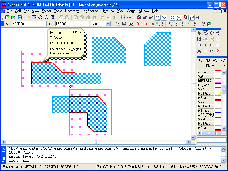
By using Relation=Inside , edges from the first-layer shapes that are inside of the second-layer shapes are extracted (see Figure 1 ).
On the other hand, using Relation=Outside will extract edges outside of the second-layer shapes (see Figure 2 ).
The extracted data is treated as edges data, but it may be convert to polygon data by using the Size_Edge command.
These commands are used as the following:
   Select_edges: Relation=INSIDE,
                 Layer1=METAL1, Layer2=METAL2, LayerR=&inside_edges;

   Select_edges: Relation=OUTSIDE,
                  Layer1=METAL1, Layer2=METAL2, LayerR=&outside_edges;
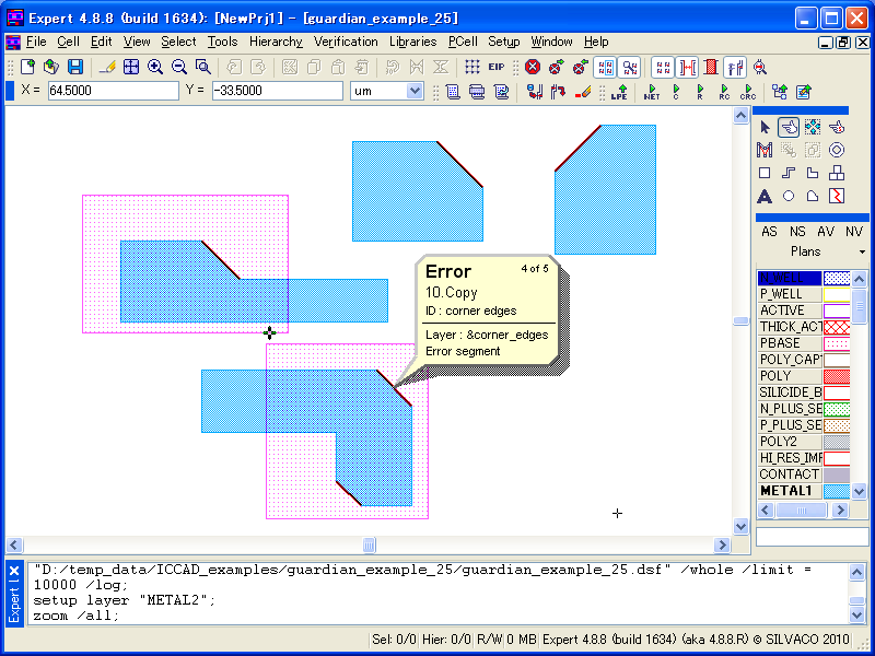
By using Relation=Corners , edges from the input layer are extracted based on the range of the vertex angles, or lengths of the edges.
It can extract edges defined by vertices of more than 90 degrees and less than 180 degrees when the angle1>90<180 keyword is set (see Figure 3 ).
To extract edges defined by vertices that are not 90 degrees nor acute vertices, multiple conditions should be combined as the following:
   select_edges: relation=CORNERS,
                 layer=METAL1, angle1>90<180, angle2>90<180,
                 layerR=&corner_edges1;

   select_edges: relation=CORNERS,
                 layer=METAL1, angle1>180<270, angle2>90<180,
                 layerR=&corner_edges2;

   select_edges: relation=CORNERS,
                 layer=METAL1, angle1>90<180, angle2>180<270,
                 layerR=&corner_edges3;

   select_edges: relation=CORNERS,
                 layer=METAL1, angle1>180<270, angle2>180<270,
                 layerR=&corner_edges4;

   combine: layers=(&corner_edges1, &corner_edges2,
                    &corner_edges3, &corner_edges4),
            layerR=&corner_edges;
The actual operation steps to check the command behavior are as follows:
1) Start Expert.
2) Select File->Open to load the project file guardian_example_25.eld and open the top cell. It contains some polygons.
3) Select Verification->DRC->DRC Script Panel and select File-> Open in the script panel to load the sample DRC rule file guardian_example_25.dsf.
4) Run the loaded DRC script by selecting DRC->Run in the DRC script panel.
5) In the Expert 's main window, select Verification->DRC->Errors->Load Errors or click the corresponding button in the DRC tool bar. Load DRC Errors dialog will appear.
6) In the Checks section, select each item and click the Load button. The relations will be indicated in the list. The corresponding error flags will be displayed in the design.
To learn more about Guardian DRC, the different command and their syntax as well as the different setup options, see the Guardian DRC user manual "guardian_users1.pdf" located in lib/expert/4.14.0.R/docs/ in your installation area.
guardian_example_25.dsf
											select_edges: relation=INSIDE,
              layer1=METAL1, layer2=METAL2, layerR=&inside_edges;
copy: layer=&inside_edges, ID="inside edges";

select_edges: relation=OUTSIDE,
              layer1=METAL1, layer2=METAL2, layerR=&outside_edges;
copy: layer=&outside_edges, ID="outside edges";


select_edges: relation=CORNERS,
              layer=METAL1, angle1>90<180, angle2>90<180, layerR=&corner_edges1;

select_edges: relation=CORNERS,
              layer=METAL1, angle1>180<270, angle2>90<180, layerR=&corner_edges2;

select_edges: relation=CORNERS,
              layer=METAL1, angle1>90<180, angle2>180<270, layerR=&corner_edges3;

select_edges: relation=CORNERS,
              layer=METAL1, angle1>180<270, angle2>180<270, layerR=&corner_edges4;

combine: layers=(&corner_edges1, &corner_edges2, &corner_edges3, &corner_edges4),
         layerR=&corner_edges;
copy: layer=&corner_edges, ID="corner edges";