004_xor : XOR Operation Between Two Layers
Minimum Required Version
: Expert 4.14.0.R, Guardian 4.14.0.R
This example demonstrates how a Boolean XOR function operates on two different layers. The XOR logical operator is typically used in Guardian DRC or Guardian LVS to generate additional (derived) layers that will be used in other operations.
1. Preliminary Steps
To run this example, open a Guardian DRC session and choose File->Open to load the project "xor_ex04.eld". Then in the Open Cell(s) form that pops up, select "xor_ex04" and select "OK".
2. Boolean XOR operation between two layers
All DRC foundry rule files require layers to be manipulated in order to perform various checks. Therefore, rule developers need a method to create or derive new and temporary layers from drawn layers. The XOR operator can be used when developers need to generate a new shape from two existing layers. The XOR function returns the symmetrical difference of two layers. If the shapes overlap one another, the intersection is not included in the new layer.
The XOR syntax is as follows:
   XOR: Layer1=< input layer identifier1 >,
        Layer2=< input layer identifier2 >,
        LayerR=< result layer identifier >;

   XOR: Layer =< input layer identifier >,
        LayerR=< result layer identifier >;
This example uses the first syntax because we are performing an XOR between two layers. The second syntax is used when performing an XOR with one layer.
The example cell "xor_ex04" provided in the "xor_ex04.eld" project is based on the XOR illustration shown in Figure 2-17 of the Guardian User Manual.
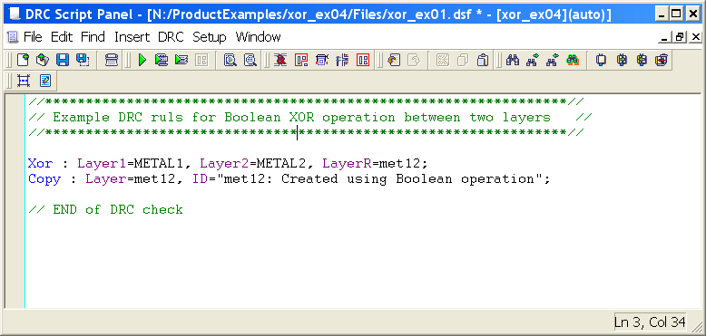
Figure 1 illustrates how to use the XOR operator with two layers. The example combines shapes from the METAL1 and METAL2 layers to create a new layer called "met12". The "Copy" is not necessary, but is used to store the newly generated shape(s) into the layout in order see the results of the XOR operation.
3. Experimenting with Boolean XOR function
Once all the example files have been downloaded and the preliminary steps described in section 1.0 are completed, complete the following steps:
- Choose Verification->DRC->DRC Script panel . In the new window, choose File->Open... and select "xor_ex01.dsf".
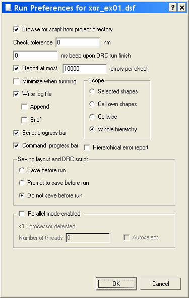
- In the same window, choose Setup->Current DRC script run preferences... and set the options as shown in Figure 2.
- Accept the changes and press DRC->Run.
- To inspect the newly generated shape(s), make the "met12" layer active and then turn off all remaining layers using the "NV" button. (To make the "met12" layer active, click on the layer's color strip which contains the check mark).
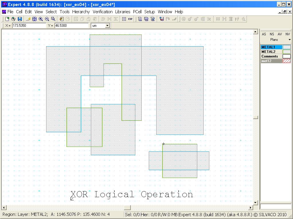
The original layout is shown in Figure 3. This example contains three shapes on METAL1 and METAL2 that intersect each other.
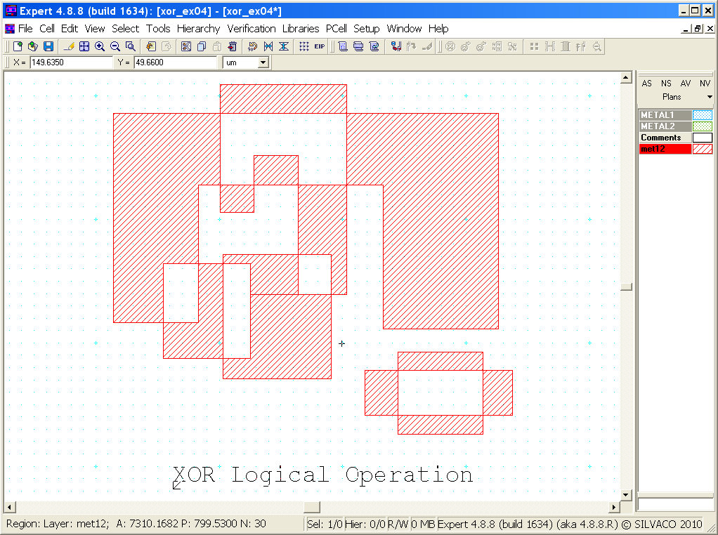
Figure 4 shows the resulting shapes from the XOR operation. Notice how the two layers were combined, except for where they overlapped or intersected one another. The new shape(s) are a union of the two layers except for these intersections.
To learn more about Guardian DRC commands and their syntax, see the Guardian DRC user manual "guardian_users1.pdf" located in lib/expert/4.14.0.R/docs/ in your installation area.
xor_ex01.dsf
											//****************************************************************//
// Example DRC ruls for Boolean XOR operation between two layers   //
//****************************************************************//

Xor : Layer1=METAL1, Layer2=METAL2, LayerR=met12;
Copy : Layer=met12, ID="met12: Created using Boolean operation";

// END of DRC check