005_vending_machine : Verilog Vending Machine Schematic Simulation
Minimum Required Versions: Gateway 2.12.10.R, SILOS 4.10.90.R
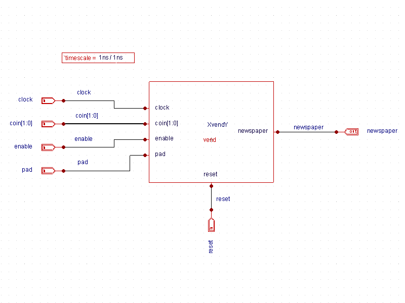
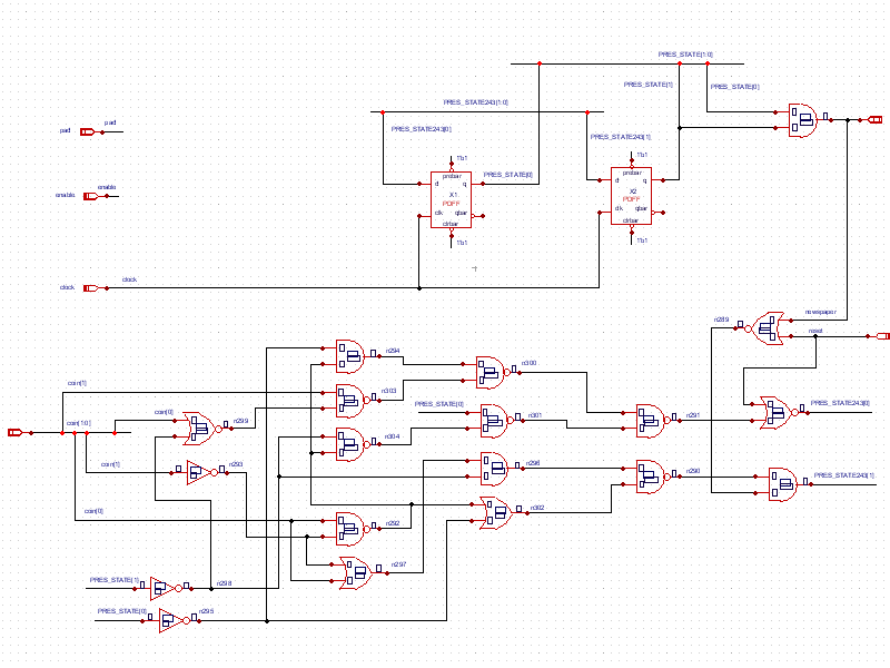
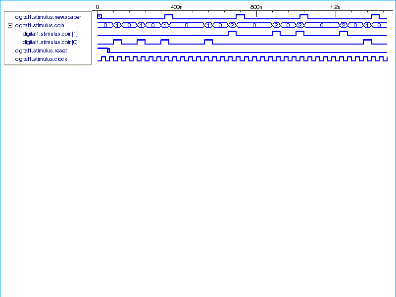
Example 5 is a schematic example of a finite state machine. The example models a vending machine that outputs a newspaper based on input combinations of coins. The top level schematic ( top_level.png ) shows the vend block on the test bench. Clicking on the block and descending shows the gate level view of the device ( gate_level.png ). A simulation of the circuit shows that when each coin is inserted, there is a 2-bit signal coin[1:0] that is send to the module. This signal is asserted at the next negative edge of the clock signal and stays high for one clock cycle. A high for coin[0] represents a nickel being deposited into the machine. A high for coin[1] represents a dime being deposited into the machine. When fifteen cents have been deposited based on any input combination, the newspaper signal goes high for one clock cycle and then is reset. The waveforms (waveforms.png ) show output from the first run.
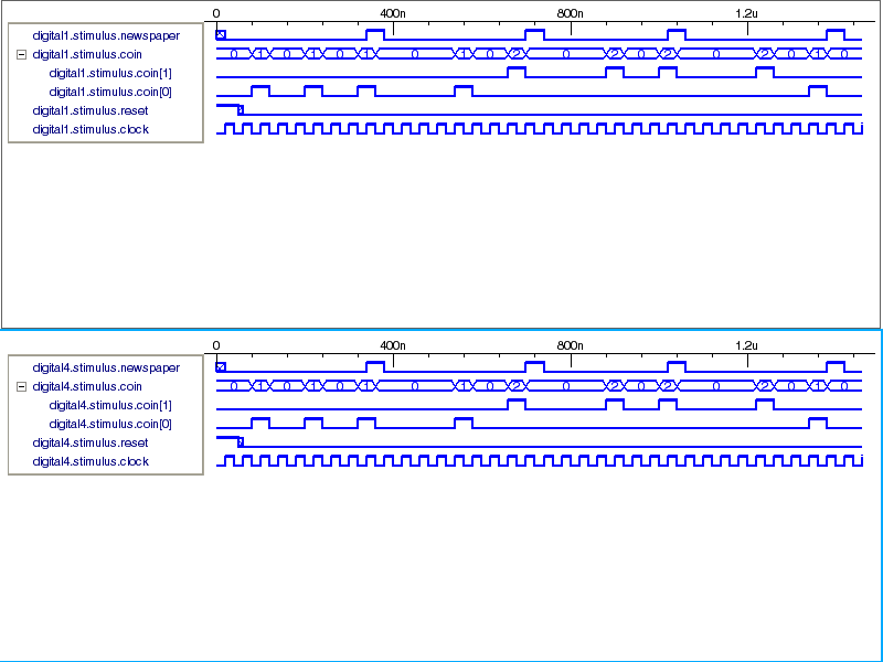
This was a gate-level representation of the device. Now, an RTL view of the vending machine can be substituted and simulated. To do this, delete the vend block on the top level schematic, and select the VendingMachine library from the library browser and instantiate the vend_rtl view. The vend.v RTL view shows the contents of the module. After resimulating the design with the RTL view, the output.png waveforms are identical.
vend.v
											/**************************************************************************
Adapted from Example 14-6 RTL Description for Newspaper Vending Machine FSM
"Verilog HDL  A Guide to Digital Design and Synthesis"
By Samir Palnitkar, Prentice Hall, ISBN 0-13-451675-3
**************************************************************************/
//Design the newspaper vending machine coin acceptor
//using a FSM approach
module vend( coin, clock, reset, newspaper, pad, enable);

//Input output port declarations
input [1:0] coin;
input clock;
input reset;
input enable;
output newspaper;
wire newspaper;
inout pad;
wire pad = enable ? clock : 1'bz;
//internal FSM state declarations
wire [1:0] NEXT_STATE;
reg [1:0] PRES_STATE;

//state encodings
parameter s0 = 2'b00;
parameter s5 = 2'b01;
parameter s10 = 2'b10;
parameter s15 = 2'b11;

//Combinational logic
function [2:0] fsm;
	input [1:0] fsm_coin;
	input [1:0] fsm_PRES_STATE;

	reg fsm_newspaper;
	reg [1:0] fsm_NEXT_STATE;

begin
	case (fsm_PRES_STATE)
	s0: //state = s0
	begin
		if (fsm_coin == 2'b10)
		begin
			fsm_newspaper = 1'b0;
			fsm_NEXT_STATE = s10;
		end
		else if (fsm_coin == 2'b01)
		begin
			fsm_newspaper = 1'b0;
			fsm_NEXT_STATE = s5;
		end
		else
		begin
			fsm_newspaper = 1'b0;
			fsm_NEXT_STATE = s0;
		end
	end
	s5: //state = s5
	begin
		if (fsm_coin == 2'b10)
		begin
			fsm_newspaper = 1'b0;
			fsm_NEXT_STATE = s15;
		end
		else if (fsm_coin == 2'b01)
		begin
			fsm_newspaper = 1'b0;
			fsm_NEXT_STATE = s10;
		end
		else
		begin
			fsm_newspaper = 1'b0;
			fsm_NEXT_STATE = s5;
		end
	end
	s10: //state = s10
	begin
		if (fsm_coin == 2'b10)
		begin
			fsm_newspaper = 1'b0;
			fsm_NEXT_STATE = s15;
		end
		else if (fsm_coin == 2'b01)
		begin
			fsm_newspaper = 1'b0;
			fsm_NEXT_STATE = s15;
		end
		else
		begin
			fsm_newspaper = 1'b0;
			fsm_NEXT_STATE = s10;
		end
	end
	s15: //state = s15
	begin
		fsm_newspaper = 1'b1;
		fsm_NEXT_STATE = s0;
	end
	endcase
	fsm = {fsm_newspaper, fsm_NEXT_STATE};
end
endfunction

//Reevaluate combinational logic each time a coin
//is put or the present state changes
assign {newspaper, NEXT_STATE} = fsm(coin, PRES_STATE);

//clock the state flipflops.
//use synchronous reset
always @(posedge clock)
begin
	if (reset == 1'b1)
		PRES_STATE =  s0;
	else
		PRES_STATE =  NEXT_STATE;
end

endmodule