003_one_bit_adder : One Bit Adder Schematic Simulation
Minimum Required Versions: Gateway 2.12.10.R, SILOS 4.10.90.R
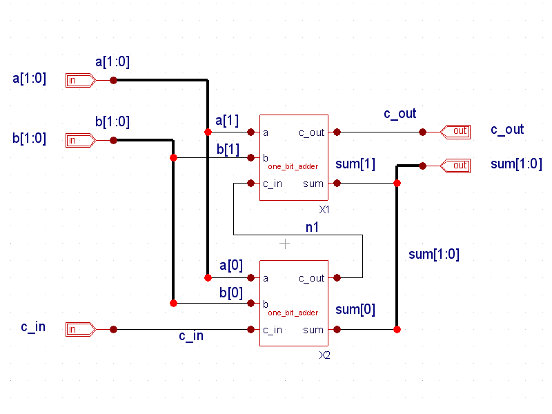
Example 3 is a one bit adder verilog design. The schematic ( schematic.png ) is shown consisting of gate level primitives and one_bit_adder.v is the resulting structural verilog netlist generated by Gateway (see one_bit_adder.v). The control file is the stimulus module that instantiates the adder design and simulates it ( one_bit_adder.ctrv). Running the design in SILOS produces the waveforms shown in Smartview ( waveforms.png ). The adder design can be folded up hierarchically to realize a larger design. By generating symbol views from schematic views, the one bit adder can be used to build a 2 bit adder ( 2bit_adder.png ), a 4 bit adder ( 4bit_adder.png ), and an 8 bit adder ( 8bit_adder.png ).
one_bit_adder.v
											// Gateway 2.12.10.R Verilog Netlist Generator
// Workspace name:       Q:\examples\gateway\web\design_examples\digital\003_one_bit_adder\one_bit_adder.workspace
// Simulation name:      Q:\examples\gateway\web\design_examples\digital\003_one_bit_adder\one_bit_adder.schlr
// Simulation timestamp: 20-Jul-2010 09:31:47

// Schematic name: one_bit_adder
module one_bit_adder(a, b, c_in, c_out, sum);
input a;
input b;
input c_in;
output c_out;
output sum;
wire a;
wire b;
wire c1;
wire c_in;
wire c_out;
wire s1;
wire s2;
wire sum;
xor21 I1 (.A(a), .B(b), .Y(s1));
and21 I2 (.A(a), .B(b), .Y(c1));
xor21 I3 (.A(s1), .B(c_in), .Y(sum));
and21 I4 (.A(s1), .B(c_in), .Y(s2));
or21 I5 (.A(s2), .B(c1), .Y(c_out));
endmodule

// End of the netlist
one_bit_adder.ctrv
											// stimulus to test the 1-bit adder
module stimulus;
reg a, b, c_in;
wire sum, c_out;


//instantiate adder module
one_bit_adder X1(a, b, c_in, c_out, sum);


//apply stimulus
initial
begin
	//test all combinations
	a=1'b0; b=1'b0; c_in=1'b0;
	#5 a=1'b0; b=1'b0; c_in=1'b1;
	#5 a=1'b0; b=1'b1; c_in=1'b0;
	#5 a=1'b0; b=1'b1; c_in=1'b1;
	#5 a=1'b1; b=1'b0; c_in=1'b0;
	#5 a=1'b1; b=1'b0; c_in=1'b1;
	#5 a=1'b1; b=1'b1; c_in=1'b0;
	#5 a=1'b1; b=1'b1; c_in=1'b1;
	#5 $finish;
end

//results

initial
	$monitor($time, " sum = %b, a = %b, b=%b, c_in=%b", sum, a, b, c_in);

endmodule