002_adpll : All Digital PLL Schematic Simulation
Minimum Required Versions: Gateway 2.12.10.R, SILOS 4.10.90.R
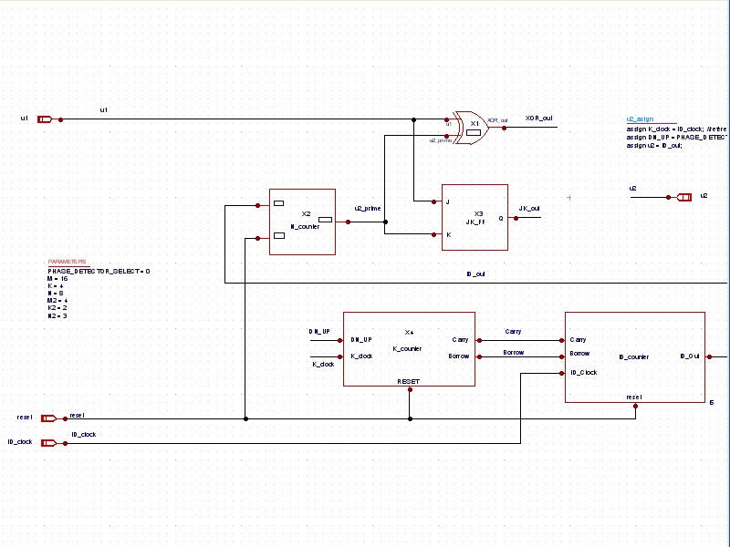
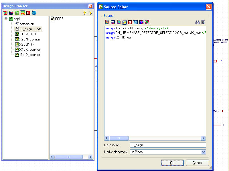
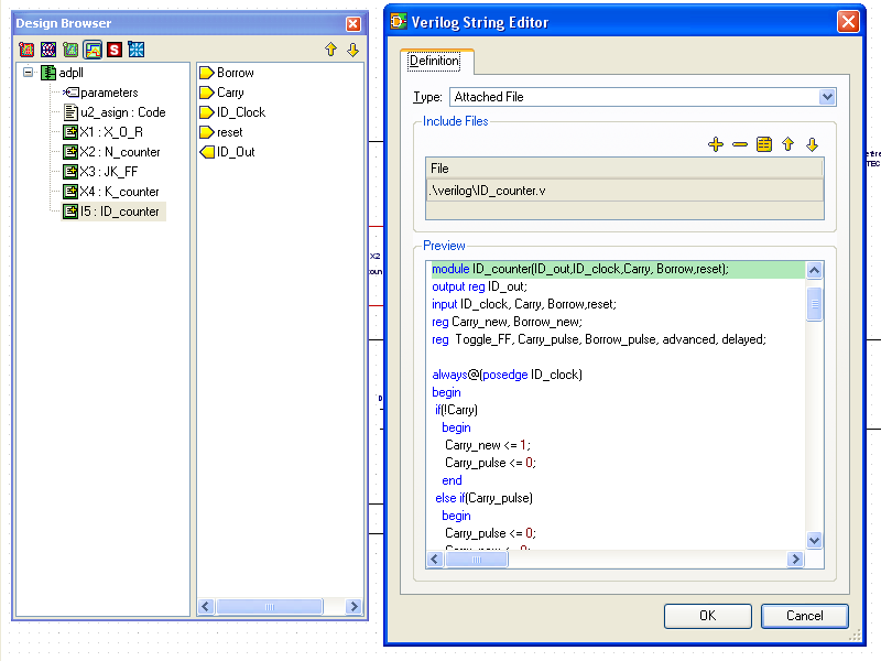
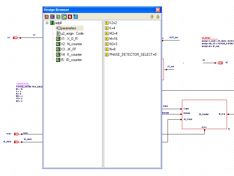
Example 2 is an all digital PLL schematic design ( all_digital_PLL.png ). In the design browser, clickING on the parameters entry displays the parameter names and values ( parameter.png ) that the module will use in the netlist. Clicking on the CODE entry for the next item down in the list shows the contents of the CODE block ( block.png ), which in this case are the assign statements required for the module. Right clicking on any of the other instances in the design provides the menus for viewing the module definition. For instance, right clicking on the I5 instance in the design browser, and choosing Goto Definition shows the definition for the ID_counter module ( module.png ).
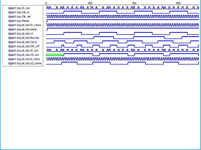
Clicking on the Netlist button generates the verilog netlist for the design ( adpll.v). Running the simulation produces a digital raw file where the waveforms can be viewed and processed ( waveforms.png ).
all_digital_PLL.png
�PNG
���
IHDR�� ��X���'���+tEXtCreation Time�Wed 7 Jul 2010 13:35:43 -0800������tIME�$ל���� pHYs��
��
��~����gAMA����
�a��<IDATx����\�}(���I�o�B����������Yh�l
0R��` 0�z���5QlK(,!v�H!��%a��#~������/X����S����:&H��k��hD`cW9[�Gs�r����9=�v��S�.���v����w�=��������y�����?����@;���Cl�E����H����`�$&��HL����
� 1 �@bo%X'N�o'!!!!!!!!��C]###���-}���]"�HL����
� 1 �@b,���$X���I���ShTHHHHHHH(qH�Q��4�h �@b,���$X���I����`�$&��HL�Q!!!!!!!��!�F��Ph��Y$X���I����`�$&��HL����
� 1�F����������HC�Q��f�`�$&��HL����
� 1 �@b,���J
Rh�
�F��E����
� 1 �@b,���$X���I���ShTHHHHHHH(qH�Q��4�h �@b,���$X���I����`�$&��HL�Q!!!!!!!��!�F��Ph��Y$X���I����`�$&��HL����
� ��ݳgO��
W��
W��
W��rǥ�(�@
��4�
� 1 �@b,���$X���I����`�$V�B�BBBBBBBB�
Rh�
�F��E����
� 1 �@b,���$X���I���ShTHHHHHHH(qH�Q��4�h �@b,���$X���I����`�$&��HL�Q!!!!!!!��!�F��Ph��Y$X���I����`�$&��HL����
� 1�F����������HC�Q��f�`�$&��HL����
� 1 �@b,���J
Rh�Y��~�E;N��PtG����hz]]��]��
���N��`5��� -�
�@1$X)
=w���{��
Ew�}
���
�Z������PW��ؔ\H�$w�6�,Iʷ�{E��c�;@� �Q6v�o7~�x��
�y.�8�e4
�I�Q!!!�� � �j��Ѭ�
���^�n�A�)s�����(����7��X�=T���}ɒ�z{/
z���B��o(l߿�S==ﯼY�pɒ���/o�1�]FF6}d���s��]cӄ��B�yV���'�n�nȮ�:����R����
f��l���SUw
w�3gKXB���?=>r�c���F#��=��)s�֯��
�?��?��I���;��?mY���^כ���W�'�G/fE���|{j����ɗ/�w~l�������?3�ڋ'_ 7C��/EH����z����>y�L
�
�l��6-Y2��^!;|xUh,Z���=l!Oz�泍/�_]�q�c]�낷v�V��5�~�_��������#C �ʢ'NW����������#��p��|��ʘ�όd V�;����&��ΟP�r����mM�@c��<س=���]2���3��o�D����=����ʯ,X8��
�=��+�����6<��-�����c�o�/�M�WK��
�
�Ç��͛}�ȏ����vٴh�@�i��W��������߷N���UN�
y���7�{�:�Ϯ*�i�n�_{�� =�sH�>�kE Iq�$Xͮ�Y��,���o��^�����v����MU3����cs��-���Sg��}���z�趫����U#X!�Z��
62��W��+����k���=����}�����^
ۃ�}!Ӫ�~$�w
;l����ϗ
\ǮB#��_����
բ��O# �S ��g�[��oT>4�m�L�3]�W�������U��w�־����F͇�`V��*����C*T�+��##gO�O�-�' �v�%@9��P8�13/�zyv���>s�w��WC���O�q��˯\x��?f7C�5�쪒�� �A1ͪ�rU�$��U~�U�
���[�_~=�]������|�H���1�o������?r����w�^��o�u|��_�ܫ�5Y�}RQ��w�
,�p����i�����,YҔ�
����
�2<��^t��ӧ�\�1�������^���; >w��sg�;$[q�*l\�zǶ�k�;>��Й��O
}�C
�����^{��
���T-�&?�=�l����g|6?oL�sd�"l���P~!�*�_���p��O�LS&U�aѢ�ׯ�z�֧ �+�
�
���<\�a�;~��ظp�y���VQ�L��㊅쪖s� ���
5
�#�s�_��2�Z�uȮƻW�?��� ���
�7�b���u���!�K>�*��%�7��K^��
�t��
��߿�_Ӌ�D�]hk|�jk�V�
�j�Ѡ3e#X~�����r�����HȮz{3�n)����H��9X�%�ٜ�� _K��%��
�:S����/�ڭ��朳��ݞ�{h��
�}�F�"��a �2�� �~���5wO��K!�`��"[
.Uw iE��3��Ŭe�M��
"~�"ߎ��v��\q���&:������+tčs�{c��ěa �|�NfV���6��ys���B?�{�,��*[:~��
��K�^ GW����W�G_��qc�
T�)�6@+��K��}̪2����w�>���O���~�œ/ǟ9
YHl���/���ɟ
�{_ol ���! �N� 'l�d3�|F%�*��Y�q��v?v�����\{���q�'�
+�+�ݸ�j�����F�&��>V��_���&�D�>z����u~cH���X��q7=�
�&��/��\����w\������`)�����w�4��q��LJf�C;���x0�3�;+�Gl��o�����[.|�
�}�Ͱ�F>t� ]�����g��Yk>K�g�g��쉪���O\g۷m����g��\�ݬ���~���T�����
Ǐ �xf2�裏����q�������N�U�q5�`�����~����;�6��͗_����{�ï�y�����~��=��g{Ug��\i�������ew�~}��5��^��?o~�r�34�_���u�h��-u�
oz�t��`�ʾ
x���i���u��~d�{y��}�0k��� �lշ��_9
��@ ��5��X�˭��z~��o�ѯ�z�G�q����i�Mr7�@C�]��ˮ�����_<�ʓ_{vv���>� =���؎�3;�l(����؝��h�Vh���ވ���7c���h�}���}쇻 y������
�wo�
��uv�?邞�g_�Z�n&��E��;3��x�j�Vg�����h�%@�����Ĭ���}����Z{����a
ڗ|p��W^r����z����糝k����:;g�
�w6+=�r���*,�R�?�v�Ƈ��O��G����R�k_�Q��}�z(��u�
9V�EV�tω��xٕ�T����d�W�Yy�� ۘ���W���->TX��8uR��
}�K�FX�����]q�=�����u~�����w�B�v��~�
�)���W�O�UÒ4jR����C%)4�����l��]FF��C�
8�m�_���Wa ��њ�a�uW�Q
����s�7�j
��~0uU��
M��hՖ�Ag�&�B�����B�S{���
�����������[�c�εU��볱1v���a�^ή�$
�2p���(@)��S�7ݓ�3�<�TH��������������T�U���
���)�9�5��#���7����q��M��O���͂283����wqe#X,�S�J�5eYFuh��N�
�V�1� ��{�C;�l�2:���͟�/�'3�%B�v��F�1���fr&��X!%�ߌ[q�=O�=�_��2Z� k��B;&F����\Xg5��)dW�
�1ͪ/dW5�f�������P�S�
����(@��W���hf��
Y�I�|���?�/���~~l�̃X�,��t�
�>��Ћ'_
������^�ȅ�
��G.�u�#X���b��؎�Ec�̬��gy�~��x�o�����t=��g�o�ġ�:Nc�|F�v��cW�w;�ȕʹ�gUJ?���%$$$�Ш�P���Sh��P��U���ß-�ըRh�8m�-B�p�E��,,���$X���I����`�$&��HL����[ ։'��IHHHHh�P
%顐�Ќ���:�B�@�)4
��,,���$X���I����`�$&��HL����B�BBBBiBu���BBB3R�
�ͦ�(�@�H����`�$&��HL����
� 1 �@b
�
� �Q�
�XHY<�S(4
4�B����"��HL����
� 1 �@b,���$X���)4*$$$�&TGIz($$4c!e�N��(�l
��4�
� �w��&v����.4�b�UiG,��Ж�H'�t8��j6������(�/-I���!dT��u�ߌ�l
Khݩ�$��j�����`oѽhI
�
�t�PWW�.exy
�Q�
5z���ӡ��7�jբ~����Ö)�3-$"�:[����҅F���:�������U���u$��q��Ȧ���2�B��E������Cc`��E��������
� 1����xq���mذ?��X��#[�,M�O#X�@kHX�����`@{���ԧ>Ut/Z؎7����<��*?.5�[�q�����`�ۑK�v��
�-�QU���^�B��/�2t�q9�2t�q��q����ծ�W�О7�9��v�f��U��Y�x��jj���Ͼ��oh���V*#CC�mѢ]�EC�F�%�ke�� �B�%�N���tT�ZռJ8���[�^L�1Y�Q����3���'F '�7�I���0�
߱朳��/��qHc�3?MU�X�j]^,�PΒ`A��gd�
|������˾=���%E S���
��7
!����I�&L�(��L����2v�H�|�@��ʤ=s��ZOȼ�
�Vt/�qI� �
]]q)�#��g����������O�q�6�!��y�OR�̤N��6:,EwW�
�
�
��D^����s�����5j�������
��
)4J�kvmɨ�y�v��ؤ�ԏ�wu����F
vfN�&q�Tr�ul
=w��
�l���l
�BJ��@CM��}�a��GC�ۋ
Tm[��#|7l
�
�S��*l�3gKXB#;���$s�
yUr5�~p�o�qX���������742r�
*gG��_�Ѣ����������n<|xUh,Z�����`%2� ���~WX��d[�X�D]]���Q�����K ���t��g
(�����U�� �Ke4O��t���?2�Cmٲ$|$��jd����9s���o��yȧ�������cW�Q9����)���,��8-<�Q�y�f+OJ���
J��dh��f<�3Ę%��&���v���Ȓ%�������
x���ܺ������ز�w�?|dμ�:m�!�S
�=�(��
E,Zt���Wo�����w�^��##��qMA O��~ڜ<��E�����/��qA��(�P�:]BB�
�Q�
6;�� ���
�,���������P�����fh��]������PH���{Q�A��"��dX�͞�
[�����'C�
��t��'L�9X��� �����CC����5�+gg�$���mT�6qVw���T�]�����A#J8hѮ����Jx24��/o
�y�芛6�ƶ�k��qq#Ǖ�����#X������X�����Rv�V����{Cc���T%X��
�j˱\;dZ���I�fش
PC�iӤR1:�K�^Y�3?6�Fǎ`
{{�%+���
��낹�
?���Wm��{V��!,`F���K!��5��נD�1��xb�u�w��'���-��\s��;Μy���jd���+s�hQ.3'�W��L~v���������>#���Pl�%4�_���υu��l�o0�
�,Z��Q��TeK�}�V���A#J8h�p+6�>C:����t��vh\q��_=�z6���?�>~���7o[��+�<�U����
�+��븠b
:�{�x����W�/���HH
,haqV��m;����v��+oޜ��
�;{����朳,����>�����Ј^j�5����<�ǕV O�ƕ��u\P�y���u������$=L��J.g����:*���A#J8hѮ����Jx24��/�りI����c�;l�/����}� �
�k�ǂu~�(�
�W?j$�A5��
���!Ӻ��{ɮ��$X@�(�����
;-�P��p���O�to�}j0
�U=�����Pt/�$X�Ǝ����ZR~�U�s��=���u�w�}��K��@>�
��? !3��&Nݻ���U�z��B�Bm
����j@��uu�Y�>ݜs��Y
�����&j�{Ј�זl���
� �h�ʊ�z\%Ѯ/o�
K�QHijh�hW�`A�*�2F����`�$&��HL����
� 1�F��Z�)�C�h�����w�h\�G��8�Te�����CM?
��v�^�$���y��:n��%����={���T)S���
����D*x��U/�����#��|s�=�I!=��R��n���[��DaKX���g[�C�b4�
���yO���l�|�
W
-}\��~9.�պ!��Z�f �
��9�F�1
��4�
� ��Or �
�EY�"��'X����D��X��9�,
ˊ���nf��;O
���G
xj�{o
7/��-Ǐ<��7.5 �����7'\^<�rx��,5��}�U!���Y���6T=��]�w�N��W��{�C1������L��#�������؛��������:�/|�
�^�Qh
;�����V�a :X��c��*�`�����Y�3V�
�a ����L���� ;P�0�s�����z�i�����J�g?�AX*�^-]�ѱ�9�,���
�P~��ɯ=���
�:���O�}v�}�O~�������;���u7.�z����B/�zeA��W_����9v��zǿ�
Bc��GU]͎kl�B��;?t��k8�A^=�zX��~w�Ui����(I��Z+4<��2tCH�졢S� �
ډ�ݻ�j�
�FX������� ���^��xCG�Ǚ��� ��؝����ydtT�~W'
��?f��q�?WU��L�$/��&05��]q
��Iݫ�Cye#Xe�a
�>����Ύ$-���7����{���S��;{���&��循���y�Ïm�n��3
����/�#4��\3�?�31����ۯ�a���o�B_����ƛ���
����n�X����{�|���
�����j���s������kFw�T9�����/��N�
��U��YH't�c��
O̖B�1ʛ3g��ëBcѢ]�ÿ�'Xcw��rZxkR
�i
��@MCC�5�[O��EwZF�$X����748Xc
���5�튍�۪U
C����EwZ@��}d����sf��K>���O�
?�|����6�胠`.B��S�\�)h�K��Ξ2�����x�o�}��
���
I�R�J�
~ dNa��X�dT�5��N��n���{�CEw ��De/4z��>}4G5x�sg����;O�rߎ?*�q �X����PHHHH��B��\2�e|��?��Ḟ��xa���{�[}��g^��W��3������`���I���1Y�U�9X��-���"�����*���g�pT��lZ����m۹�Ξ�y���W.,�������D@��%�J��4�dW���6�S����>��[}�����nf��_*\q�=V"��-0����{��jC�}��ڳ�\��P��
��_����C��/.�}�9��2Ώ�����������5d�.L�$w���@�H���+{�5�e�<�T���wo|(����
�_������Y�������8d
H�
,����j�:XUƦ\wm^7~�+k��
�@+�� ���1�
i�-����������s�*cƥ���Z{{o��Ew���FC"u�g����x��k�9�5��꼐�����Pg��ޅ ��@��h�R'XqfU����
������G��>�СJ�`�Ξuf����7����8�}ǟ
տ㊛6�w��C�=�Z���<�Ͱ�o\�z�Ïm��8�UU�}�M��z�����t��'X�;���G�:�|b<-����n\\�^O~��J�$)��L*{��
����ʅ�����z���?��
5B'l
�U�_��h
�?� (��@�j�i(g�.!!!!!!!��
��
&`
��L��8Q����֭��H��
e�4I��4��Ïm<���m;��7N8��$wR1�@������2���S?ݛ���"X�Q�K����ae�D<�����Pi�V���������>╾�6
|��{��곏w�o�{o�p ��hPv��'L@�@�Z�[���-�I�'N��Ї>Ts'!!!��uuUh)�s��%<�Jrb����k 0��/|-���W��Pm#�[�2�眳�����ZB��4�Y�j�"�/�|��K?���Sfk����Z�_
�B��N
����h\�;<����__�`���)�СZ��{&dNO�}v��}
z�������*���1-0��ů���u���k�~�?}>�0.��q���ޘ�
�`��\0k�LUi-ޯy�چ9X��-��ĉ��$$$$$$$$$�xȵ��K���JJk�~5�
�6\"�h,���$X���I����`�$&��HL���X�
��ٳ�
�p\��
�p\��
�p\��
�h��RA&Ж�F��6���`oo��ٖ�������##���
6f밥��7�:�[�̼_'O�^�t���/�������n
�Ʉ쪯o(�%dW��1�YCC�����������FX�v�x��sE�����*���:��mذ?��a��
�E�*��}h\t��#G~�Ew&�
Ew�(�����>�,�[t�
30pˢEw��֭O
>|W�����/ݵs�䙞��W���gGC�,����'�c�~�p�-4B���C�]�I�`A���
�y�
{
�����Gs�|���/ś}}_
�ע;�z�͛
2���w��
�,j������uw�kѢ]U{�Z�s�E38���.�$�D
*|�
��
�v�=ׯ�Ȝ9[ú�.��ҥ>8�:��͡�Õ�{+��W��f��=!�Z����щ}!��]!몌q�e��6��
i��$��ǻ)k��j������,Yrqo�o
}����n��fW##ݵd��~�srժ��,�#���B1e͘��Y�
0��`5�ϡ���j��m�!�@
(]�Q!!!!!!!�V��p�p��
��9gYX?����n\
o~�+k���?��}c�
�:��7|l�W�,����œ/_��3ïo۹&��S��W�ƾP��f�K�@k����Fv��ʛ7g7Cv�ೄL�ɯ=[���H�h��؝�|�KO�}�e�{�C!
ˊ�� �+.�\\_��[� y>�'|�I��mo�W�o-J�$���i�y����>����-��N���g�����F�.���]0����>�/��u7~,|�_~�%� p�oe{k��H�к$XС����M�����C
����k������om)��,��)~���/�|��K?��β�k�з��ꫨ�o��ා_6��{x�ƾq�;gZ�ؗ��o�N%w�P͛XV����9�ʛ7?����f��5v�����{_oX�b��m;�\��؈[���c�~잳�g�u��8 ���߸���ȉ��-�ՙ�
�2�}��/��&��i���9�LGxm����m;��߯����%9���o3��܍`�%�0�T5O㯭�*/���n{�`�$�Ш�������P��%0s����
W�~mv����Ŵt��5
^����(@��9�O�=�n���<��#`��Bvu��cU_�
��Ɛ~ݽ��Khd_r�u�c��X�k�}��
�1��D:�k 0���%���L��ٳN�to���N=�/]8���
W\��Wϼ��Uģ��������S��X��-�%ޯ2�B�
����}�^Ն��b�O�
�!���OH�Z.�R
�
z�/����V��_%ܶsM
�Z{{olWެӽ����o�DՃ�;{���������kSX/Y2w���E��ŵ��K���rWR:��|�߯�`��lZ��ѐ`
=�����q`�������� �;���� �B�18ػt�ٿ���n�OOb�q&_�x�\��~%���D0�>���'�P��u�FȜ ^��K��*��Pȷ�n�nؾkב�.���d�L�W"�� �:�=����Ѱ=�C�输�B�BBBBB3�����M�v
m�^==���������y����.�q�PȖ�W"֭����}),�n>�/�u~��� ���������څw�Bg�_�������
�5�~�Ua�����~{�
&�
�E�u��>�c
l�9_������:�����ް�Fؘ�Pڲ�ٰ1�����M煊�d\_��N�𣰄�x�7��`X�%��>��>�/>{<�����
=s�H|I�
�a�;�ݘ��ُ�ʲW}r�$XS��R�K�Y?���]���c)�������:D|}b������?�ٸ�
�u�
��94�1��W�[��&<��iS���c$��D�}�ֿ�z�����C���L�f���${m��_
R���FUW�R�$<���]��I��+s��H� �V��u���*g����t�$���"�o,�-ӕU�ʇ⥨��>~�
;3�������5��,�p�4���� ��cW����џ1�?~a�C
��+��v���������8�������r��a}��~s6���;����-5�Z�h$<�Mr�N��4UOth̖*��>�R�X<���O�G �f��/���?���;O
���wm�s�%�}��~�._�-'����͟��@����;cv�!��֕7�ͤ���_0���G�Kh��̪�Ք���t��
�U� �x��:�ׯ>��Yy��U�k��7�S�Ӣs�?����[�*UՔχ^<�Jx����sk#/�5��o\��N��.���Y�_���\��y�%;��
B��^�Ɛ^�쎳����a�Z����P���8�UQ
&����e Eq���+)
^}�<��W�[��vb�J�Y�9��2�a�͚�q�4��k�4=^�.�W����G�s>�D�& ���V�
�dޯ��
寚��F]"���IU�)4*$$$$$$$�8��L��/� �z���>9�u�;�S�������j��m�-B�)jfWa�9[B
����ȇF���E @�������ӧ7��x��y���D*�
�E�vU�������F��:�,�����.}tj��������>�r1�Tzzjբ����
\�hѮ��_�o�Fet
+��lY��7��{q�P"m>{���'���`7e���n-ޯy�چ:X@s�M��9X���)4*$$$$$$$�8�A�K`j:jV����Z�_
��B��<���7��_<�����83����kb��o$���
E�Q�(̎���4�sȮV�jcȮv?v�3��ғ{��6>�������Ј�Zݽ�Z�zG���T��
&`k�����WMUy�ڑ��#X�zl�j˹�g��+�����a
��;?�*~�yF��Cu��?�&�zb/�{��#Ͽx��+.�\#G}�
��8��2
���bǒ�F���`���͛ ~lc��m;�\����o�cWqch�z�������]�W������\��>`.N�KN����W�O�r���=i���W�"���I�Q�(��)}K�:�9X���)4*$$$$��:J�C!����/iCɕa�G�+�
�S�����'��b
���!qb�e _����T�>O��_Ys�Ƈ_=��s���؝
z��U̿��$��-����fl�}��#�_��S?�[�H���p,��B�t���o��ɟ
=��7C��3�=��ު��
�H���R�|���Vȫ�����
}E�.��$X���������
}��շ��K+n��S��;{���F=n#X@^龔eS��.�
_�j-�|�J�b9_(���=����F���f"�@���R�ӦA%顐P�f�F\�lJxa��p�h&���D'@�Ph�D��et�gj�
�1s���bG�Rڎ1�Հ'��HL����
`*�������0E�U*e�^PF���+]��={�����q����q��%9�:Z��� {\g�_+U��~��n�M �R�T�W�c
��9gY�����"��
9��~n�}���a�{���Wm��vT�?�lJ�w3%�ܘI%|��i+J�u���V�x��ˏkK�f�+F��2��T
�SL���\{���!ͪ�N�$X��Y|��9�,�IՊ��9q� /������g��P�W(�^��$�3���v;]"�pD��(���tu���
yx
��!�@���?R��eW���{x����K�wyh��]]+7l�ڹQ�K�P6%��AI87f�W�(�9�,�Vq�*k4�
,�`;FGw�uu���
k$�V���npp���/��jؑ�v���r�����|����`�$&��j�_��I�����*�ߜ#X���)4*$$$$��:J��v
�Q�
�3d�&`x��87f�W�(^�I�
��DXmx��Ew�hm�js�l-�
�@k����a���M�
l������� q|.��.}4��`�f��j�`FF6��a�oY�gj?9;��fh����������76�U:���ǹ1���E��OJ�9XqL(4fxX��T���<��i`���ÿiV~#���M�����a�aÁl}��
K��ݿy~�,
�cT�1v�L�c�����Ж-KB������#G^^���Ơ���3���B�F�
�ȹ�4�q��RZ�5�E�zz�ߵ�h~c���Υ��s�
��*������N��d�3̅��x�'%�Dx� �����#��T-[�
�U��
7{{�"��>�1��
�T�C+������Z��}��iR�A��~�� ����ղ����`U�Y�i�`<f
����`��Ǟ����D�:WCF��X�+�od�N�v�ݡD�@
�K�&4a�yi��d<�
`�U����i�%�(�P�:]M
��S�h���F�+�� ����P���(I���7;��l�2z�����|t���7���~�G�n���C��
\���
/���:|����F�h �V�����������%X�(�'�T��u�����V�Kc��l(�PWW�=^l��(��F�JU5��T
����
�dը,m�T��x#Uq�:�X;�|��ƺ�څIu����2�j��dX����
ƺ��B������#oW���a
���h���}o�_��q�p3,�Qz����?��
�\+�����\�j�+ۿj�����12���)BBE�~�� �����ɍ�6�j�d/VƹJX5j�*!�0cJWhtRS����
,��-\ht�2
�*��XeI�T��چJ����I����`�$&��H��ĉ��$$$$$$$$$�x�,u���Z��~����I����`�$&��HL����
� 1 �@b�+4�gϞ2t�q9�2t�q9�2t�q9�2t��K�Q��4�h �@b,���$X���I����`�$&��H�t�F��������Z=��(�@
��4�
� 1 �@b,���$X���I����`�$��������P�B���i(4
��,,���$X���I����`�$&��HL����B�BBBBBBBB�C
�����(�@�H����`�$&��HL����
� 1 �@b
�
%)4
���B����"��HL����
� 1 �@b,���$X���)4*$$$$$$$�8��(�@
��4�
� 1 �@b,���$X���I����`�$��������P�B���i(4
��,,���$X���I����`�$&��HL����B�BBBBBBBB�C
�����(�@�H����`�$&��HL����
� 1 �@b�+4�gϞ2t�q9�2t�q9�2t�q9�2t��K�Q��4�h �@b,���$X���I����`�$&��H�t�F��������Z=��(�@
��4�
� 1 �@b,���$X���I����`�$��������P�B���i(4
��,,���$X���I�����߭��V����IEND�B`�
parameter.png
�PNG
���
IHDR�� ��X���'���+tEXtCreation Time�Wed 7 Jul 2010 13:39:42 -0800*�
����tIME�(�_��� pHYs��
��
��~����gAMA����
�a��W]IDATx��
tUՙ��>�{oB���>�cFff�&��Xǵ�vf�ku�֙
>�\�.����̪.����X��kT�U-.�U鸦uFG��
�tf�%� ��I�㜳��Ͻ��W.Hn���q����>�$w��?���>�sN������С
�������6 �������,�����!
����`�������b ��������
���+�h�`� &�`� &�5Q�����0�`�����`�������b �������,�����!
����`�������b �������l4
L0�L0�4�&l4
����0�`�����`�������b �������c�/��4��_����䱬灥�K�p6��� <�P�����r>^R/KN`u��÷�7�?�g�ң�����]�PUuk���ܜt��l���4\�Q")�qTg~"�k)�>P�q�F;X��s��*���
:���2�ei�d��X���W��h��f�5Oĥ
2�cq��
�N� ��2�d��zFӭ��*Jo��>y�
6n�vl�������
c;;�r�p{S�� X�ʻ-�}� �;�F��P�Q2&M�^L�W
�838�*�ԃ�z�*sT�N�c�ǫ?&w� � �3N������O��s4L#�����_4�z�Q��?�ecB��6Ƹ�
=��N8&���^5��,n�;�d�h�YVM�9���S3 �|^#�^�;nզM���s����
���J�`6-=V>��V��-G����ɸ@�:$�A)���r�1�w�-�l���zUf�U��+J��
nsjP�@M4˭�T�[s�T��Cd������L��
�s"
HJyiܗ��,ai�gH(�OxF�d�r͎>u�s�Ύ�o�|�p{S�� XO*U�>B.HD�p"�X�XÎە���'X���);w���s�i�iȩ�&�h�]�
es�hg6Ӆ࢚�2^��6/Vj���v}!B]��x�ȮO��x,�q�-�UzH�y&�?R
�����3՞���a'E���4_����.�o��u�
b�͔��5�TK�1��
,�u�s�������
����_wF* �s�Aт�Q�6D �@��#X��Օo4L#�T��vt�Q/���R��y�v����,SHɒN <��O�D����a�f�F'�g
������T���"��
�
�$4g@�����n�8��,��h̀����`a��M�h��p7]�5/�pƘ�//���E�_�$J=,�֝6�F�7 ����[N�k�[U�?7�(��Ŋ���uzW2�|c
ԳO^�:������/l�TXˍ` t�%�,Q��j?��Z�z��y��߿������[?p����>;�\�n�˽Ԓ,z(Fz���_�F�`ԃ%��p�@�Ҋ(u�(Ѩ&���Z+o
]|��U���}��t]4�3c���Y�����Ԕ�z���
���bp�f_���}1��SA�Mb����
�C�vS�IH��D#�
� �;�!��s��5�4mr��j�M�8M����3��ؤw�X��
�`�
^+xIe�2@��m�B�bdn��L�N��|j'�ˠQH[�u�=���8����.b�wa`��ڜ{��
LQ������5�i�J8�udr�f��D ��ڽ}�F�+:-��}�)����
,P �U�T�
�,�?�I���PW������W߯�Kvݨ��O}9-醾�i�9�?$��l@=Y��Rį���VWi 6�8[�
6��o��d��J
�I::�OEc��=
���
Ovuu�
�4y��ʭ�h��[��5=����8o�JGɊ8�����+��p�-Boy���k/7^��n��jh'�
��t�N
s����c��)^g>b����Tb
���UWd[c�|E���Q���Ea��L�rD���L
��4yu��X�ޟ�fwdέ �z�S���ԕ��v"t��OI��4�F:���9W�+�ƪ<~ǁ푽�g��gy?����zIj��96=���G�&TWW��5�g�PH�c�ݏ<ҳfM��
�0�~�ʯ���@��+Qo�I�u�(5�=A1�/
Lg%�Q���re�q �����V������\M��>���w��K*EeI��IuE\E%��:m�'{���Mk�-��&�
J&�ݿO�|T{9�M�����G_�o�O��ֺ�����]�6�����_o����[Z���K�R]�8�W)4���e��g\z���꺗.��
��.XI���4����݊8
��m�b�w�X�p��Y�͛c���jk��8WNA]�r&��3:ҽ�*r
k���D�F3[����˖
u��¿������d�49˗�E��iQY�Ro�ò"��L�Z�p�-����PWc����
� ~[��
{ �dR���,�z"?���a�`�Np��wj����M{�؎
�7m��s����Ͼ��X���L��
�}�(���w76&UTGG��j��ٳ�P�@`�6�u4 ���**{�V]����PNVHRN�{SW��zW?��R-��>�ue�7���o��w����ް7�F��}��MH)��RW��D��i�(��=m��hu>X��9m��
ݲ�D"��}��ܐ��B
��B-/�ʚ/A�D��j]�
u���ƌ��%�Ϯ� �}y�Key�%��jk[*irS���;�u��Ā�g�Z5���_&榎=�+����a�J�����ɪ�]u�vu���j�
����%�߲eڦMd���S�#�d������Hj,_��\PW�`�ђ7e #X��f�]��
;��E���eQ6����65H�冬�����+�6s/�e����ױ��y�
�7=$ʱ�~ ��o��9�*�z2v���=9�=<(*�o�0�u"7�X�P��-[���}����݃��rny���@�ѺMƣZOr�_c���!^&�΄���Ơ�X��.ZEV�dg��o�)��ؿ}ϲ�S�|y����~�����e�z7N��r�.BPn���n���g[�QW��7wv�~��s����
�$��Cr������w�3�s�v)�
��ݽF
��]���I��{���n��lrO���Y ����&"�h�A�t_��
&�=�;2`�P��κ����v�<�*=�E�J�x,��Ʈ�Gb��9�`�^�˞;����w�M���p_>��tA
��`���a���6�'o�f����3Ȯ�j+?�|��;�Z���v����( ����0���w?PRUw��_��M2�z�sfG�3g讣Y1����t��ID�t/�Ғ3�����͜`k6�ni6gq���
�`P�
�lu�5cD�%�MphTLXjo�m
�߿zU}_�w������ֽ��z�UV����;g��7_}�Wf�R�ʝ3<��G�|HN�z߮K�r�I��{����f �B�e��O}�������,�=���q *ӝ_�H}�'
Z8>W@#�2^��/�}�4����䓆���\�*��F�lْ��H��
��?�2�ʄ�y��x]E5�����@XHDW4{�4瞮�,WY�V��Ӗ���6� 9(�Ί��Y�bmy�_�V@D
������2�:��=�*���=�~��S2�a�=�u�\a
�
�N��R�L��)
R�h��
���*�ɓ2
z>��Z'����G�l�1���}��1Y^}�/e�����2?�Pm�h��@�>��G>�� ��D�|��ϛt��M2q�_�{��
��=CR�T�냊rZ�
T
�R͎�Rcy��S0�U�N�:u��[�N�̞Ξ>}�����'~��l��?7�k�F�P�N��7}E��=Z�uKn���J���
����h���M��9�֛�>�_
y�(�����wB�"t�`����s�
���"B�g�Œ+�X�k/�LG��9�EtU��-JMQ4��e���F����w鏊����ώN�ʞsι�4�ǞW��0u�*����cK�X�����'3�����4
��"L�)����\����b�0 >*�D��*�"�@���_��̯,���1���G���D��
�2�C��ĆD��7E��v:��EB�Ei�)�&����`���`+��#X��F�ҐhU�S����?v�ݲ�,�n.؇+
T9,�*!��؟�U@�[�}%��=r���ϒu��rp�
�����9X"���+��G{��s9m������~]��#X�U����쇫W�V[W�Z��A$���I&S
g\
@U!���0s�>�g�V���|�0��=��`FT���}�Ю�5�Z�|�vs��5;q�QZ�H+�3�+dt%�1��p��dt%O�ג��"ì\te��u�=�hF.j�� �,�'��~��I�&�'�t~Q
�R($5V�/�4c
���
��k����1V[6�A�P��b�7�C�v�jQ�=+ͩ�����}
2{�G+���+ǥ�A,���T���0s�dte?����B���S�&7���sp�W�x'����n���#��ڋ�ܟ��]fL�J$�[�&��h���:u��64%�):a�`�ѕS��ا��S�
6���*�W�u
�=XUT*T��|��DSM�"��b�`�+LO�D��1���K��U�yZ�k2�{�<�:�[e6t�BH�s��P��ૄL�"L����[��������_S@!�s��#�������
FW�_�*�|�v����
��/����(�/,���^�����
@A���/��
�@i���{���S��<����e�=�P]H4j|StB�`�T��`��|��DSM$�1����&Z�_�@� ����E_��xD�j�\˚nY�
�{���'?�=�(�վ��;�t�Z��OLg�:6Nx53��f�GD�S��U�U��
)F�rY��1V�H��
��JC�U��
����pߙ�j��UW�F]mmm�c�v|V��j�f�ՙ�<� �l�d����5�����S0|�K���=q�UWl���-�GTWt��_�@ig����N���4�[�����
��?�uf�7x��1�=��H�G?$�L�%�CVa�����P�~
�g���BWחeM6�
�A�"dt�������,�����s�����j��( ,�*f��8�D��7E����h ��l�C�&s����2����ofp����F������ N4
�&�D���?�5뒆����^�(46����;o����u&+�Y�;w.�O����g��'�۟HYОcS�b�Xe�*�Ń�
�����@�t��` �4D9uu}9��}�::~��4_r�C"�{
�K�?Ivh�Ț�����"&S��~M�Z��_;:D��[[��][�??��^E����+v��/ߛ�7I4�v�Mi�=�!�
�������BG��Nt^�Mf����l��쾍t�J��U��|����z�<;���~�H(Q��t
=�*�CC����(�
D�4k��JDW�����V3�GVDW���`ف���oh�����f͚�s������ۻv�mņ\_����_����q��r� `E�cS�a���t�"Һ+�#H��o���j�\5�����������ႛGq��
�u�g����:�z
9Hݟ�
��#<=�`�]w7�g�go��m�L�yʔI���`w�f��(W������"�To����_}��j��α)C+��}U3���C�y�"�"��$冲���;�8��yv�&�8���\�> �`�W����=���:D�=}'Ln����O
Tz6Q@ePjh�.�� s����۶�=/<�Ͼ�!�~�<��#֢�q����(�����{�w�~�����c��-�eM�q`�W�9Xm��D-��
ߏ��}�
�c&�}+{:���}u�MW�0�jC\��iO>�V��lw�?p����Q�ԺO
|��xFW�rْ��>v\}h�*]j��ώ6Df�IŁ9,�YZ�7�=��$��l� <8��R�><��Wޱ���=�`�Wm���Ew��(:�TD�&�/����`�,��Pj����D�� n_��}�w~�"��O���\ul��jf��'f�M$�I���|����7E`���/�>�|�}Y����~�7�Y
��&��#:��I���;�_{���/=r�
�~�CQ�w���$�j�#k�J�0���G�~{���P2C� &��q
�C���J�`�W�9X�P2��D��9+[�nܴu���Uv��qZ9�n"^q��{r��+1!�
7]��O��!��D/<7�����Z�a��9
:* ��ȫ�"��K��1D�!b��:7ҳ���_�f�tGYhY�0傆�]M��t���:b�u�^{��H�|(QP��]���;go2-�ϡ�E��ٸu�����}+{��E6�Od ���5q�bm�|k�"��~9⓫>��uٿ�G9�6oޜ��H�����ז��ko������L62��wE�s$��\���D�IC��?W� 8t�M��|ϛ֤����:�����/�١�i/�
�߳�|]���z����2O��`�Ͼ�'� ��B
s���ό���q!|���p���}
�"�����}��@�#����s�j��:j��F�78�/ϻ�ɚ�ٺ
;�V9��}6�Y��
x�¼�q`"&��WQW�Z5wU����O���b/O�GW
sڱ�7�>�^��崽v���yӋ�`���c2x@7����c�n��VV�MrÅ7�.�s��c�?7(���/�OZ{�|�p�e�� 8ho+��cvtX^ zC�_<��VV`�W��"��CN[[�z~��3if08a�t�I.%l�M���}+{��E�
� S-�e�M�����+�p�&֙���o~���p�䎧�x��>� }z��_��qn���#������D�1���M
��=���'z��E��S��6���}���}"��e�1� c,{]p��݊���ij�q�J=<�V��2
ݪP&��1V�g�C���/��f���_ ~S�/�&O�iܭ\^�}�,������D�r+^�D�j6,Qv+!���S�[^YF�j���M��#������v�w���'�Vi����*��,��ѕ��k��}��:D�yx�N�)��9xε��J��/����I,��ݣ�>��/�Mw�Q�eP
�:R�~��K=��]�;z
q�6o�.b)QkQ~r�
oY�?�y�}�~s�,������u�Λs�x���g���բ�
MeK4��������D",u���O��6��~�
�j�wX1����7e���[�Xr�|A]�
��D�����s|r
GU���N4��/X�B6�h�Q��������h���-�h�9X�TJ�O��k�W���s�e�����k��l�t����m�7�ʳ��Up��
V��D��ts.M�+���_i���y�8W����{�������6(
�FQU��_�^E莮���@��h��j6��Q�5S*�&`Wv �e��Dn���-
!e]���M�����(�����y�����
�����i ��M�&
��}�ը��y���V�g�`�
�]
�ޯ�7��?�����4�`�W����=���:D�=��Ort��K�}�t5愜on��eu~����d�w��}��ƭ+�W#��rAC�#)?,�
��-��#�*�3T0;$�ᦫo���[���W���Ȳ�m���~�_�8"<�Z������
��]ɂ� �$���3�ò%�$���/
�
�֢�r"���0�a
�T��Fm˖tڹ�J�yf�w��(\{���dFWs���{�*��D�����>�F��.�y����9�21��s������"�"�O&�e�\T&ϴ˛7��<�hT��[p��l�'^������緕;ɧ�n�R9v%
�[nϖuޤ�V�Oz�`
8p��7M l�#X�"��oQ�Tw��%;s���W��
|�ݙQ������V.[z.�5r�v�#��[�2����_
v�0�g���$�b��G��"
b;{�E��9��I��&���l�F��>i N4
��D��*�"���W�o5��SW�L
(�t��` �4P���+�
����������
����V9�2r�+��5~�Շ�팱���U��|���
oJpj~��
X�6V��^�"����R�^�s�
n��s7,�
�H;+N�gu��+i���;�X�U�=�c冲�L���R�t:�
�"�
��d2\�g�
����p_�~q�V.Z�d�cT����a�]�E�Vb�#-O�����C�_rK�Y��t����T����8�-��T��{9%uF@
�:-�*K)���:������Y��KR2�r�]FG��q,��2C���y{�҆:Bn�=#�a��/����I,��ݣ�><�*PYg>%
� 9H4j|StJ���Jթ�X��yW%���m�Or���_,+�L�Xr�kt���
�G�Pm�-JMQ41o��%
s��]\<��v{��*B{-;����S*�{������]�O���!��F���\��WrW��Ҕ���q�RɃ�x�,�Ӿ\EX�H4���U��U��;�ʯCQ�6�� ��篯��.�w"��l薅��>�`�`�W�������s���LT~ӡK�Y�{<[��w�ω���n��n���<����{�3�����n% |���F�_a�`�9�E(,��+��E�5BwOψ���1�E��/���
�,�*�^���Qn(K�DZ�}�������$��vI���ߪ���ݪ�l E�
�*�i��"�"ܗ�7�����7�]P�7�
yr�3n
�3�:ï�Ѥ��M��;�VyDh%;��XX G�d��^�L���,Bu����9�%�!�Z��c����������l�R���X)�:~���?����@%���|���
��a�/<�K��*|�@J�Y����=�es_fh�rԄ?��ɳ����Ҝu*�XV��&�d�v�Vz�*�+�xF��7ާƞ�
@���x^�x>;�ޗT6����`�Ru�8�'�!
K9�2|)6�҂ ����/��y�[,��5�
���z+!ߢ4�E�G�5u�T�mhJ`StJ���X;:�/���j�>v c�9�R� ���H~�
�R*�$��ܮ�C��H?Q�� �VB�Ei�)�&�"��bG��
c��fz���f��R5���L��Dn���-
����{�r�{�Bn���}�.��|����W�
|����
,�
?���֦� t�+T���
5;��Dm��㨱��
��Ղ�y5���w�wq�
����)\a>�g
h
�3��~=��ÿ|w��>���pc
�B�`�l��/�!b��'��#��՞��
�1����@"�������
w�?B���
V�Ǡ^���
��DW�
����
,�*�*B��0��
�������"Ѩ�M�a
@��-JMQ4E�v�Y~ߡ�D��� ��#?>ܾ�
1
L��|�
Ҿ��;�t�Z�'
��\ul��jfx[�̸�����+�U��[
���E����� ����s�j��:j��F�7����r�~L�헖���!����y��V����!GX"��������mUZ����
1Vy��6{\
f�?*|{/B��X����2�܈@�9©=�@
��4
�U�U���w'�rq�%�9킟��z-/��G��I]��<7�u���L+V�L���"
q �I��K�`�0˽v�n��Y�
2�
~��5 +$9����]���Ǟ��ޜ�3�IDT������l�XD!�2
�a�{�2:�e�c��.3,ghR�st�r�������ކ���$$5�)1FG��q�ʓU�},���-J�_S_��CCGE�����)}�e $����a�$-����ŵ�k
W�k١���}�:?��\��r�
���R�찒�hQN4�'��*�D�Ucc_SS]w���Γ��l{��e
�"�.
�U~�+`&S���s���� ��eRL�P=.�f/���/�},Fb4hkkS�:�:����鶀��Nҹ{��XJ������f�<1������c�_�C�܃O�>��`a�"�#
��T���iCN�[�b�LE�����kg���8E�qɆ���*����e�b
����l�r뭷�}�<<����\FW긔�*TYSB
�+�#X�� ):����?<қ�Ñ�����3��Fſ��p�]�`�
���rF�KK��{6���8�=��{�J{������}
?��l_�/��n��!�F�K���"�hQ��D��"
Ǩ��YB�����IJ�!��H
5�j��4Nr����@��p�CS�k����_#X������2H� eF����y
c1�������fX����%7�(M!���P��
�C��jh"ѨyH4���hQИh4��ݑ�.����kס��/������DeM�Z���}����i��kn��ѣ+ܕ�L�(���q �#X��c�R�yT;w�:{�����^
:����0��0Fk�gjj:������O45�����%��^�]��X76��M&O�pܯ�Ղ�
�`��kg��~(g�74\.u���5��\9�,x@,�@%��@$
s����4#Ѩ�M�`��|��DSM$5�F5�"
���)B���͘��H��TJZ߂Q������L,eۧ�E�u���bz
�F��H�
�}cC.�"�9X����`�J�w�
,��S����"���H4j|�*!ߢ4�E�F�C�QD�D���FQU��������fX����`��hF�������fX�����h��&�0TB�Ei�)�&���D���F���p���@3,��������4#���Ќ�
��@3,��������4#Ѩ�M�`��|��DSM$5�F5�"
$EU�!���fX����`��hF�������fX����`��hF�Q���P ����(�H4j
�"j$EH4���)B��������4;7���T�=�T܇�D��
�f\��q���@3,��������4#Ѩ�M�`��|��DSM$5�F5�"
��F�
�)B��������4#����̘D��d��
5�)��C�S��� �b-�M�"
��C5����d�����с�]��Ϙ������Wd�C� �0�Y�JG��뾬(��콍
X�7{?��ա���K,��K���1fK:9�Q��]���z�M��͚���8%+��n$�T����)"2�.ib
��ǰ�k�d�?�M
���s|���
/�Uk��Y��^�G� �#���ޡ��ޕ��J
��|EVTˋ��[�r����n���b
����V9���A�U�J%�`%��*Q����fL����S�`�y�
^Fwl����������/�M��oeOܯ���TcN�7i������cǃ{>��Ӳ���~�
�>v��P]����}RDNb�Vz���/�;<��%��`��23&���S.|�A9
r��&M�����'wt~�/��k�M�`��|��DSMf�i��0�[�}{�F�.x!��eͶ�=˖<����b+5���HӀ���Q M��s�dD%��0�������������1s����La���¤R����1�=�����[�����?7�.���1b0P2�N�����7���H�@U3fKX����#��C;��zQ�W�D
��)�F�������V�y�-%���(?c�
��/]�˖tʦ�'w�E��;�a�
�J��G���Jȷ(M4E�dF�Q�H4���hQ �(��I����@�����1V̈́9�=�=x��}+{D�<�`o��
����1��ͯ?
��G����;�C���bcR
,w
�{�,�����Ҹ���T/�,�o~�al�0붯͍�p��@�2��c\ʝ�ey���%
q ,���^�$��m_�+�)���]�xw�C��D
|�M�`��|��DSM$5�F5�"
$EU1�!�������*�`����m�n0�����Ō�K8o��c#|x��gR^�o���5q ;���.�X��>�أO��Z�lI�ƭ+eYh9R�/�y��ǎ�}�����`]<���k�p[�
<-�}��gl��/ZJJR���20&��E�n���53���eK
~��q?��
jB,��ѕg��@D��d�t�ݍ�z�HQ�����1�Fi����$�[�&��h"ѨyH4���hQ �(��1���D�m�{�-�
�+|�,����� ��|t��s�֭o �+|�,����̘�.-[�:�ݑK
S��>����a�֓;
�w�
+\��������3ikZ��
�6wْ�m�/L��N���P
�X2H�q�
��[�R��DY���z�t����
#X
�:u�go����Jȷ�����R����
%?�x>$5�F5�"
�hTX3�1��JcN�L��أ�e:���$3&�����e!|���_nz�ѧ�>p��P]L
�
�F�v�ֿ��/N��d�G
����1iT"rz��Ŗ���/
�&s:8�.�����4����/��eK
~�?��;�;����,�`՞?��
���<�����m_�k�K"z��b����@52i
���
ց�zӔ�&�0TB�Ei�)�&���D���F�"��1�(���)����4#���Ќ�
��@3,��������4#����,��F�lْ��H���C�=oV���&���D���F�D�CCGg��22r��������>�R�h�b�h�P!Dt��ۘ�4���,
�X�3�jKcc�X��]�R.�䡁�߈u܇
vn����jCC���?!
"��Y���(jhh����a&�,������":�}�@a�`��4eʤ|DuTV͞��[[?+�-����]��gͺ$�C
c
�����g��"
b���)cy��<�#V~�+�C
#���i֬K�
]a?�
��f�ź�����N�Y@�`�� �,������,��Fi
���Jȷ(M4E�D�Q�hQ#�(���h���S�>�Ƽ9�
9�n���ψ���F��Mg*%�"�ڴu��
y��EYs�ʞ� sIJ���b}�w����n�?pP��~MЌ�
��"�q�_�ux��i��^<��M���5�̜~��]T��ȅ\�_��\�8�j{}n���_4#��� e,�
��c�@j���ׇ��;d���Y�rw㦭�
=�>���쿆��␦�sg�;F�fd��k������#
�憛�1�{o�&OkF�*��Eh�f���'L��̺�#�j�}��v����rAÂۿ8i��������i�7�&�,T
�`��hF�Q���P ����(�H4j
�"j$E�*�(
E�Q����"���Ќ�
��@3,��������H���2{��Џ�
��l�]��^��Y+QQW:�e�#0QP��zC�^�E9���U3a�X�]�"�Al�����Ҕ)�E���G�L�XDA<�d�eQP���/�������
�?���}[�����ED�u�wȵZ/��?7(��Z��>vh@�Q���\�l{w�����K���?�ٿN���]��D9�V�4�h��)�pْ�w��XDA<�����Z��V����k�����Ӣ
��WCӱ�w#}.��k�ԩ~�Д�&�0W*����Q��>���(Xc��Ԧɓ?��;'[[?;2rB}��,���ܱy��!���/=t��M���s�D9��/�ID*1
�<+�m�{
Mr8P,��w8傆H���=��aO�.˙���j� �+{
��TJ��,~�[��~�_z�w�¢[��
��ׇ�|���o�^��U/�-ǩOqx��q����ϮD��-�ū[�
Y���'w<
oY����䫖�j���a��������ﮣ���b�w�bQ���G��"
��]�����n�r}�����ȸ�Q)焉侕=� d��
1���D��y��^Qk�*����X��<<���K�"
��0̻
�,�@
R%�h%�Cc �1��X���
`��ar��DY�`�j��U��Ϳ�j�\��:3Ϭ�d��pQ���
��紺Kv�����q%��� k�ݑ
�3�Ysc,ϸ$��
��L,v|�YBq��tT�pޜ{r��G��݂ۿ(��M��+y��}c��>�X���%�
�����K�䰷�
oYޠN��et��J��ƚ sDӺ�-e~ ��N�\%������7Ο!O&<���X������*��S��e5:��#OZqei|�q��X��T��/�<$5� �
��oQ�h��)e�4ê���C��V�W?�G~|�}��>"T���������>i?�sձq«��m�3�>"m��R3�1��J�`��hF�������fX����`��hF�������f$5� �
��oQ�h���D��!�(�F�QD����L�s��y���[W�w�^ zcޜ{��
_�~�l��=� ��H4
�@l:S)���,��E��qT��j��U�_z����m�{jϟ/Q�eZݷ�G6-[���F��3��EP�*Qn)4�q���������/�M���+�-yX�\�p�w��(_<��ܳ|�O�A,�0��0I*n���Sh
k[�
w�E� �?p���7���0��������,��a�=�838#�
��ݲf�֕��u�Λs�,��r�JV���ǎ�,o�{�,Zx�j�D.$��Eh�f�+���<���ד����#���je��]��ʝ1�^�/
E ���8�]ybUUa���f$5� �
��K/!_�4�d�h�D$E�H4�(�J4�J%�KcvJċD�����E�������fX����`��hF�������f$5� �
E�Q�*�)q��P�F5�"
$E�h�� �����4#���Ќ�
��@3,��������4#����,��F�lْ��H���C��}�R����~]�F�M�&��J\�6D�QD�D���F+Ö́9GO��(t"�(���O�L�^y�C���X��m�{Dy�u+DY�G0,��p���UEA�_xn�5����3k��F0,���t��y�o���cǎ/[��G0,��0ƷV/��0GU
o^}`�kfNw�
�M���&q ���H
9:u�ݍb�5�
_e��������7�������R
�J���"&�q����Wk�EhUTtey�`
8p`�ԩ��iJ`�J��^�_�{R����P2eh_����xZ�Yk�6�M���ĥkCA$E�H4�(Tp��*Q��TS�Er��.��
,��P@g~�n_*�Ru1VV�V�'��wIQ�`�� �� ��*����M�m�$w��������4#���A�s�Uu~p<����
q�o�,����<,�V�M l�Ci��K��r�6H�&���>�hQ#�(�@�Q��/
�}���!�C���F"��US��!���#�;��}X(�jO��::~*
bm�n���(Ϟ�Y���(Y��4��td��
�ߐ��[Nf2�"��+v��~vC�f��ܹ@�,���T
#XrLH�<,>�$�<�uu}yd�Ds��J�����9E��4[�� {m
��E����1*Yp/V��3����i��Y"�AUcc����f]�V
�'8�?=���T�O��?]]_N���a�(]�X"���B�[˃im��}
����
Ҕ��avldO~��
=
g+��$E�H4�(�hU%�7{�㧀�V��ʎ�*)���ɗ�����i����@,`���
�� !�U���fX����`��hF������D�4����������e�h��h�hQ#�(�@�QTN��hF�������fX����Ui��J�˵X��^.س�&��Pͪ4����646�9*E�US�V�O+V� �E�M��?��E���dI�͞ˬ��r&9*����4M�R#�
�, �r:�-�j�β���_��H�jO4*���Ƴ��S�gI4
��h��
n��tm�T{6�.'Q��6�DZ�ʟ����ȉ���tt���
���������t����ƾL���O�QD�D���FQU���<����Sg��z;�Z�v�5z&q�������H�*
�ܘJ��t������
5��(8�֮����Ӑ��Ɏ�܋c�T��3�D�
��<�4UyS���
Y�J ;6
s�P��������$E�H4�(�J4
��
block.png
�PNG
���
IHDR�� ��X���'���+tEXtCreation Time�Wed 7 Jul 2010 13:44:22 -08000%����tIME�,*�#ؔ��� pHYs��
��
��~����gAMA����
�a��p+IDATx��]
�ř�����C�PQ�(Y�F�A�z4�VQA� �q��ue�*�5��(*bP!Qc
x�n��PY�h��̃�
��}��j����o�;��
�8�G���zw�[�|��_�TA444444444�4vn����{��������q�A,
��
M�44444444�34������������KCCCCCCCc?C,
��
3
mذa�ȑ3�$����$z�۔N
e�� ���1
�zp��!B�?���Q'#��)���s�Ѣ���Z�{�H�v�dH�iTj�Y&e&��i�!
�3-� ǥP�*D�
��j�N�
n�?U]��nE
�G�Z��<�j8��c
P
�A,���o�����|�
�&I�}�S��IPz�&�ʰ�~Ў�O��=����E��}K�d��&��C�aQ4sE��Y�%�OG�iQ����r���b�N�M0
�m�04v%�#���4�T���X�����k��NJ��֖��2)�9s��:�dL
dz+=)��S&-3�R���E=�hh�
� AW!#߭����X\��9��I�f
�M3I)ڑ%0���W\�pL+㐖4��!!=�`)�^���rTs'mqH���LA�:�i�!Ӳ=�h;U
�Q��f���B)-j�� �Ⱥ2R��~S�'(�s*}���C���eftm3S��� �=[I����V��!����y6 ����v��"��C]�b��{�@�!�����ݏ�|[�N�l��p
�ظ��Eu'�����[��q;��S-��/^�0!�jV���A��$��� �c�`� 3f����1&b����Q����Q��*_0�ش�ŃOD&�#��0p|n�,���@!d
04!x�C�i�2�O��&|�������
�x����dG��"���*�!B
}U��m{�8���z�ˮ^�����
�CQ+���
<�$����j�Oj�� 7jl�Hg���(�}1�
�Тѳ��*
�=��#�aä@1@�qI��������)&���a��R�������,�Cޛ��ym~=���X3�w�
-|��:z�9���
��j6g��tEqQ��6���Ηբ���bW�
ɧV$0���g|G���Ԣ�|)$�n�
��٣_ܴb
n��p
��]#Q�L�C��Bڄ��*!� "�T(�
S}R�R��
�֦��nD�YT��Nz��HUZ�⾉D�H�^
/!/F�^&
�7"���d��W)1dW[.8��i*
#8�8�I
�������V.j���3f���h*U^b��%�e�1���˟?�G'�����~�WV�P]��>��4�$�%��� '��w�m�!��;��;����W�\�!�
�m`W��n�O��|�9�{I�+>Nl\�]i��/��H�vM;��E�۱sv(v���C��xku��K���=J�D
��%�L1Ɲ�^�u��g5D~��/�:u�o�<[��&f��h�TD�X"փ��v�.��E
���)�
�אE�;��(vE$�
Lh���s"�F��
�K�F�By�pؓ0�Iạ�]�
x�G�e���Z��ދ4�&�=��Ԑ�rr�a
�K!�T�|���o���7v���o�B������¥�^�UՑDC���mjp�
4��i��G$5�g6K��ϘP��/�f>��G��oc���a�y����?n����T��6��T�Ψiyi�S��"������^N�CU�7�/&���ϮS�i���Njhh�C���fxd��k�tҰ3@�P��쐊�k/��'9CV���m��XƄ���g=F
u&-����.��`)j�*�`1�0 [���p�W�!4,E�NJ,����p��
�l�Ȃ��5���jQ��$x�UA?,�Ԓ�� �J�.�.�P*)�����_<�~�u�OS�ʧ?6��x�t�½�hU�
m��Jx��pD����)/`Z!C��=ƌ�Z��S���tW���&���e@P.���s'>����T�l�K
�_]������X���
K_Y��>/9�w���I��l�K���̺e����f���%�Z7�P �]��g��0�����;��a�����·�,�zW\=1����;��:"�&�I�E���%jgfUO���S&(�MpF<*\����LbQi�"x��ի� �c?��
�FF
�o^��ɯ^��uݼ�p��UL(bN3p�2���j�O�
�IDz͇���̠&g^(��� *��lYS@6 s
�
�1��ض�蚦�ܶc�PNeC�^iQ��$¯Q� �[�)�h��ϾR�n�����C��
�M��5�Q�P��5�e]�d��V�܂2�aw��=
���4A��?�� �
U�t1,�Q�ܗ6���~����}�F2q�g���]=
���/fF�3�_t����vJ���g��af�b�����z4����a�/y�"��]�k��'�>���gM�3 p���ً�8��l�m�Ip/%$y�l��� ��*�N�,�~��N�Y�|%�hh�OxF�\��)��p
��H-�c[r�����U>�^����?�K���cܥ���B@��1������A��]u�Ѓ��
/4U���O5D+:��Ɇ�0w*�����rhg��:(�)2m�
�D�'���G�TY�����1�fUU�vU��d�6�"3�
��Z�⾉$8����S��
"���cv���9O��xb�� �U.
⡶�v�?Q�?�j���`3�\�%��V{��a.Jq:HrgX�V�iAO�{��+ɘ13��N6;!�"M�{'���%���^B�]%G�u�����]6|�����U���X��9�Ĭ{�9��l�Y0���?�*b��>����ki�������8#&|����°*�� 6�`�y�l�"�W�=��vB%�qb*��t9u2��f�QX�aFT��9�����A5�@`�k�ME�
~k���)
V,FD��\t�P�$�I��`
�
��V���{�
!�/��G��
,���.�����ۆ�~�%f��
D{�h��g� N
}�N�X��ZD�ru$�Y���v9zƆt
��n!A�
�|
J+��I����
.�6ۧ����A�gj��ۗy�p9QK��8��CI�v�Cv
� I�:����o��#�"�� "�
��ŃV
�V�IGP��kvN������@;9�]=��vto�Z
���-dK�S����\�UUU&=F�I��
��F�l�7�M,K�r���Qs��Ȁ]�b�s�
�_�
>����-�?x ��������
v"5ɜ������y��7��F?�C*|�
�h�tڕ��'�i��)v�yD�絧�9���6�ح�Yt�{�m�,\Fd�q�;k�7�t�}??��k�y
�ᙏ��fZP��|��=���m]���; �(�<���=3�ÿ�P��\��3�\
�mU��Vث]���A�s�lR^V�SH�j�
��`� ���艀�n8���r{�w�PG2!�g�x
!�$�����{��LOg���'!�$���T��~����~���{����"_
�$w�!
h���3�!�
����̿,�*}P^��φ[�� �K���s`7K���G5���I[�!
˛6ҋW�"�8�7����������3L8�!�?({�b���Jc�!��E�/���d�%#
��%
ϑ�&��U��W��+��=^O�K���.�=�|���h�·}�n�BYh�H5}�m_�۳f��A�%����ſ��.�����Lz,�myf�/cp���ڀ|�\��kW����7Ĝ&�f��Y!?���`�����(�¹�̭
�7$ͽS<��xVU�m��͊�O
O z�Y�e�ɴl�i:�D��3���((��~/�BZ�
P���,���JR��/��|���أ�d�D�^v�8+gL�ұ(w2�|@^�އ^� ����z��� �^
�N|G~r"�����-�ĺJU���\3��l���6�/����\���[g
�"��������y���
�W#
ȋ�P5F�����o
_�64���L��D�,������<'oxt%&\�s���y��
���������i��}�%± ��T}F{'�H��W�&�'����2�cKXr�$)b���ă���b+@{�^_�`�D?z�k�;� ����
�_��X1=���k�3�(��S�����5�F��7/�1�L4��A)8H����Җ@T� �#X�_�Xcx�i��4��M��//��6�cڎ8�Kt~~M.���,wR`��66Lc�r�'C�͈������a[���F��C
�(���2V�
�ы�2���VP
�ߏtG\E�P�O*� �E��PU�HQ�N�n~���N]�<.q��=1����0Q0*���F�����
j�jg!F
z��y�Q���"�:ivv��˞��f��F/�*z[�N�V�ԎhA4!_8O�A}"���R �R��h#��&��Rt����Hq����M?F�Ț��
�D���"��O
����?Z\^^ncb�[�
-��GA
G}�p|�W�Ӷe���t������PW��$��-��
4:�1��[�^���/^|�
�}hZ��볳3��~����P�����c
�o��������
�H��ht�c2Y��w?_��d9�
>�J-�H^%c�tp�r��
�& �TB�呑~C
�ݎ��Lv���"$ ���'�����#t���ǖS�e�
n\G1��R]@W����c Ƙܜ;�hqA@��d_�!���O�7ٗ���h�: �)C�_��@ō ��ޔ3n�"Z�)z��)F��
��L�g<��WO?��+�?�z��42�o=���ˎ���nAc��D�VѮ)��A!�Ly����x�657��&�Z�'��"���Y����
��lYgoEEE�/WA7�Ύ�Ws
Vt�zT{���)�`�;��sf���=Ն�J`QWJDu
!q���IEEBV�Z#�MMMT~��J1�<��(:S-�"
�� E�zB`<����B��l.%�����1���eL5�`������}4����<�����%w���
��j,^�";ތO�>���g�.�o�%ty~��@����0VAAPuUVV��Z�)��3Q����cĘ��H
S$�(UW��i,����!���
�}Z��U�2T.��ԉ���o��<ʮQ��t�I��R���q����S��hT��ʏ���H|^Cq����2K�`��
m�W8���`��M:5��$�8���S��,���A��A>�`�#5���E�
.�bb|�:�p���|�!)����f�,i������i��AP��O�k�]��5�E(M�
ˏ[WQQ�8X�D��
h=
�~��z�'#���
���X8����T] ��f��utt��-?;;s���JlD�,��
�p�� /��x@���RB�ۋ�aE����Q~����Mub��rkvj�v��p���ݻ�x�d_E� ��OO6 ?���E�o�A�o���ͥ��t�����U#l���ܻQ�{ڶ$�f���gdqAu���
%TW���&*c���
�D���z��
n
hx!��97�n�dυ�љk���������ѡ����s��E�YE���Y�ތYO=d����£VB�k���5 ��I�e9�zvըŖv�(�s�_>��9���}��o�, �,��I���hY\P��0i�F%z|��G\��cLij��T��*" �����H��D� �%E1��jv�5
��GMĮ���&��.��nF����'�XI�}�ҊF��h��ٷd�\����!���ţ���VD���U�2p[*u�r�E�_]H�����+
�����
R���u6�c
�t��"��-"�f�! ��x52����\���_F��v<5�d�(�IGee��Lp�4&&WW�>Z�HZ�N�%VW�$�^��]���Cv!f ��
5u��5�&\]q{M��{Ά�4%���$�^����*�dM����F��j�5hZv���0d��塬,jx��Pw7�<�h�]AIG��"�"Ė&.�n�Z`a�*L �?��fs����!ef��ݭI8E�(VR�S�N�
0�5�xx���hb`�Pu��X���Ⓨ��O
��m{��auE�UW��}�l4c�X.��j��J��2�>s���l�9u.�)U���V�I�am����
B�c
�J���[�
Qz:K{B�1��:
��w
~�|"+��{�'GU'z��g&pc �cC@E��d�Wq�uau1�箮���'" d�G&��
(�L��H ��@ *����
$wUH��<�#��df����3���WWW��}-��Sէ{R5�9�Կ��mE{(r��n����͛g��)˗�{��N�4��d8?��d�7��"W�$#-�
�n%���'8/Et����۴i��!��+�3$ɳ� ��j� �Y���u�|NDW�}�.�����&���(z�6�f�xK.̪=�zӄ��O����j�eO�5�_���=*�%��J��c��3;$�wʔc��ߏ�����]�����
k�D���<ٙ���M��*kd��n}����I_��
gm��E��i�ʕ"6:�� �G?z���J�\t�ibAn�>}z�݂2���X@��ai���`�=@�{����3HU��m?���F��j�u��{�ȅ]XǼ����>����1����D�w� ��}G�>��%���YwČ����o��:�?��iS��v�ҥ#�b�4YŌ�F?�>2yV���a���겓�����q��
��_+
?���>��%;v�s1���<�L� +e����@+�8A
�
����TkN��'ܶy�H��'�i�n�
X�
cYw��W��οP�}7M�1�_&;?u����S>��I����&;1f��}��/�Y�l]uk��c�-���CӦ�?�d;�
<`�
1E�"�*9�_���
箄�"��"\�\Կe�L��7���5��iɒ{���O��O�
�̹M̵�ߍ
qeKq�h�՚D��z[��s�´��N}Z��@�Zs�?���O�/�L��\qE��7�<N�.B���3���,�7���o<�T̿��/�Ϟ���
�"�U��
w�PJ�mO��j�lM,Oӻ�\�XwL�j@���;mݺc��e�l_�V۱�^���"t�����&�J���q��u2��=�r�FtU0s��9�9�?����z%ܛ"�x��\sͭ�Β1�t�� ?�e�BI^P�R�^W
����]7�~�
��)��M?�9篼忟Ц
��ԣŚ}��Zs�;�P�gW����fY�^B�:�]��P�4�� :�;D�����<�ݳV�Ff��u���+m�Hs��d;֬�������
R��p���P�V[�ƹ�PN9��c����
A�Y
"��v�fpn'�c�ʕ+�O�[���T�&�ԩS�~�鎎�
.�w�+��m�Ҋ-�w�
HY�½/g���*�����
˗�����bZ�#���������c��}����mϟ��=�䱲vB�^��C[�Ͼ�n�����#y3��jte'�
���c��ۤ��e߷&�eg��7�6�
P�=�`��j�:C���fw;������?88�����};�[n�_T`�+��!:ƪ���k���F��L�?����S��w
�K�_���#%�g�ju����㮓�����R@)�`�0�?�edh%ì�_���b8� '�?��X��
<�`�fɚI�Z��W/��m��p#1���ad��yTN���ƞk�s���.1���]��L��sw���;�}�H����S="�:1��-�|���
7���6I�XZ5��˰g�l��>�r��̜��t�ܮ�6�#��(�,K��]�0K�{���kGW�"�K� J�� NdFt���5Z�L�z����\�v�`dە�5���g�8��I�����;�L���vy��
�}o�~,�,M�R���ʣ�i���?�7��"�2��s\��k�Y ���N���>vlU�c�\0�ag]u���g�+i�
@{
�Z�
+����-�I�ь?)b!�p���j�i�Y�e�!1�]�
D\�R�4`�����Y��f%� ��+����D�y{!-F�� um3
�B1��ײ �����wڑj�&O���]������~$�*�ȴ��| �*�ZF[�^��dZk
o>��iW����z
�Wo�7b�?�wzZ��P5 B��<���
U�
�+�ѨY��5�u��2�.���W�2ۂ�p�
�~��z����
�1��ܝ��D��B�
"d��wN�>�ۙ���M\��]��i���h�500��7�g���j��u�\�`���������
���rJ\�F�
�I��z_@j�i.� 9y��t/�wt��I��J߫�������TV2��a��bAL�J�K�&pS�^r�
�BXɈ�%���CD\�RܔZ��z�"��X�K� zhPDZ;��y&�{�.�<�5�&�TH�������U�(����βge�qZZ�P-�r���Î��
��)�d��8���9��6y�'!%��qJ"߲�h�
�`9�T�H,M{(z��1�����
� ��~���}�z��a�o^���J�9�=����M!N��'AI�+�.�wVM
ku�5�۫��8���K�P�>;�F�w�
�I���.dY`[�����2�zc,U�WۂդJ6t�D�QvbO��z�
r�ѕ
��
��̫-XqEG�a��?`�O�P`.��>�`�-�rغ�^u���Ȏ��`��෧U1����� ����_'���`5�~)�u
�����������; h���-�`@��O���{+�Y�
�bo�Ҳ��f�Q�c��h
����MH�v�g.e�K��� �5�g<���t��'��4hV�h�~4���w��_��S2�-A3m�z�����>���E��1X��ͪY���?�O �;�rB����βge���Ʉ�g�j���3
�Y�~�`��c>Ӱ�lj�+��7J�}z��F>���FuEW1?u�N��φJ�1�{ݽ�{�ap
�h���@+�8~
�)k�x&Q��S����|��#�7�y�E��݁�h�i�<�F���@��g5r�Y.����9Z�[{~=��=��
K&�>�.�||���
��V�O�$�y���+�,���!�ʖ���֓�][�p�;�hoo��:�`k��5woƿ��Zk��k�i
��n��T�I�]�
�_\�%��1#����6�FǨ'����
;K�+O��_��d��]���A2�r�r�l��;U��@�vpO~���9�?~�[�( �W5V���µ�]�뫍��4m��^ps�f�wp_�#�𓑓��� �N�>B�}�b~�)j�1X����
4��Z5~����i�rr4��7*q��K���o
�������o����#��sO��a��ǟF�qo�9�4�[�-���
�Z�D�c�l��_ӯ][�@��A�
, ��ŧ9����FLj�ɽ�v�f� $Nɨ�mН�)�.�-��J�e�
��,�q@�d��
Uѕs�H����*@q�v
�.w��
"�z5��;�4(�L����
њw�?�&�{��c�c���pG
���
r�2=���m��A��2Br?���2B�'w��'.�Z,�w� 5�����L
���+Љ���*��
Z��k�x
@���h4��)k�x&Q��S����
�k���CO ?RL4*�$w��ecG
=��"�zG�%��+�z$
#n
���
g������+��"��Ӝ�;��^�<�Xn���\���jǼy�)��eܝ�3���ѐ��ie���S���� 6�ؾs��Α���M#vwK�K�Y���H
�ӎ���f(Ô��u=U��?U�\pW�V+����y��瞽ȳRD?S:]@�\���X�o��ܛ4_��aݦ㻏�g6o���^$�ܸ�
QF�e�Ϝ�H��/�e
��}��ݎ�=���W�<+�?����c���_���7���e���j�,祘Ăg��nX�Y� ָ�����-�ǟ�?d��a��\�q�|X��fc����M��~���;
�u�t
,=��>��H���u���^q�x)�by��>�S�]2��OϞq���9�s�jAiK#
;���rȆ�7��[�s<�ނ�Ԡ_w+25���l��
k�v�$"�Ϝ}�����?�y��&|�e��F)��8-X߿��O��V�h�Rj�F��NY3ų��;� �� Н5N+W�;�;:�D$X�����c�
�Ȃ����<2�sqes�Y��Q�����wi���;N��&��P?��s�t�x6��]���Z�Ѻ�`-\8���
`�pE0"��#-XN;������ �
����{Y{E�����'dϚv
���]%��
�%����@3�
���6��{
yb �x��+���
��P�3����h;�E�F�c��WE�c�����)�]�����@+�8~
Voo�
��{JFd�
���
]��[����
�����G;�W�7��h4f
V��~��ZZ+p�|���$C�Q���n��U�)��"t���)��-�w��M�XB��)(�x&��]����m�]�"��h�`��(��1X�N1Z
��dG��"�?jЯ��ՙ���"��h4��)k�x&Q��S����{�a�&1w�#gH4
H4:F�!p�fGQ#9Ƭ�dc��=RX��Ō��H����6:���H���Q�ЎR%�,��g��tgrȨ�Y��cEk��Kr�t�5�;:ed
w�
��v�r
�
��s��,�
���PF*�&��"��)�����&1��Ў�u
VX��R��X���jS��*�����`y�B���i�r�z����X5�%��1�w
����mZ��
c獊n��h�X�9o��+��r#�D��[�z{{�w��S� �x��,g�&�a,z��
��Gv/�w'̂r$�?$
#f
V��~��Z����D�6E�Q��C��1�fr�]�����@]2=��hn������.w�����3����-X����ez
V�|�����ّ�������nz�����RK4
֔5S<�����/�~�[�[���oh
�� ��7V�
3�O�����,�y�"���0�IIDZ��D� B����r���3��ivܣɘ�Y�٧���|��&�ܿ)pwz*�hG)���a��3�y��9d��,�q��� S�4J��-���k�wt����N����(��K�a��3҂�c9�n3lehR�{Ef|=������:y�`�2��
��|H�+�1-X��)��P�LXD6@�X�G�-��ū]�"��hX����`��(F�������bm�h@2�z��v��@%�h����
�!���2�L4J!���bX����`��(��G�����Ź_�x�[��'}}�
==�x�UՐ,��P8�~�\ѕe]-&f�B
��h3�u�A]�4S�5 ��̙���s��`��"Z���ӧO
g�yOO��O?T��I4
ȪU�Ү�(�,/�
|晫��~�i��տ;�ۜNC���̙3Ӯ�(�,/���,_n/�\��
�D������,���xw/@ƌ\��a����y�*-X����т���L�$�)�
��@1,��������#�(P ����GI^P�F,���i ��U��.B��������#���P��
��@1,������<�3�ի
b.�,X���])��?�E��ʕ�p�5b��o�c�]%/>C?tC����#�(�s?���g��B�5Ns�yD�Q�)�����s�\1�7�y�i��T�f�Q��<�3箞�g��
md<�c۷��&�?�z@�`y�r�9rA�Xb�/�C7X��v�� ϸ���@1,��������#���P��
��@1��i H4
e����'��F�"��P��
��@1, ������{ �r��b
v��v���(xT�[W-�%B��?�L,��{�]
�(Z��������-i���, ������˶+� �瞽�ӳ?�i�v�� ���ܺj�,1���'9k��?ܐv�� �H4
�9��!�(��q�� ���PD�e�]���>�_�`��(F�������bX����`��(F�Q�@8���F���
@��h�������#���P��
��@1,��������#���P�D�@�p�� �H�9��!�(��@!`Ť�]��3,��������#���P��
��@1,����H4
�փ�
8�]/�P)��F;�%29s�eo8tC�U�eH4
��PX����`��(F�������bX����`��(F�Q�@V�Z�v�@�dyA#��J��X$ro�̙iW�K�4�zH�Q���,"���P��
��@1,��������#���P��
��@1��i ��U��D�@�p�� %yA�o����@1,��������#���P��
��@1,��������#�(P ����D��R�i H4
��PX����u�]�͢�z����Ӯ�4$�����_|B.`�eYV�z��
iW
�v}K�+۞�
t��(F�������b$
��
@��h@�8���F��
��
��@1,��������#���P��
��@1,����H4
�9��!�(��q�� ������bX����`��(F�������bX�����h(Ns��C�Q�)�4�?$��(,��������#���P��
��@1,���������t�ȑ��9�|xP��
�$�r�#.��7�X\v���4��x�q�p�D����YD�������bX����`��(F�������b����@ڕ�\����'�ʖ����
�@�q�� %yA�o����@1,��������#���P��
��@1,��������#�(P �V�J�
��X����C���̙3Ӯ�(�,/h���D����YD���څ�YiW!
,��������#���P��
��@1,����H4
�9��Q�T�&��i ��U��.B��������#���P��
��@1,��������#���P�D�@�p�� �H�9��!�(��@!`��6aY��v
�!���P��
��@1,��������#���P�D�@�p�ȟ���ؾ3�^ 6�h(Ns��p`שr���=W�_�tݔ�Nӆ�7�/zG
|�\ �(��@�;��ܳyV~n��?��Kb�����5"�,D�I���`����@[���'�W>�y��ӏ�X�����3�/�� ���}п��)�lx|�\p�<����C=N���X/���\ ���m�ܳ�y����_�{��O����M�'�ӳ?*�'
0!�P'Y��� QYՕuyeۓr��
����W���_�W�M�_��c��$;oX����~ֲ����� ]�`���扷�`\�`�;���b$
��
@�4;eh�M$
��
@�4;eh�Mt��(F���1���X����`��(F�������bX�����h(Ns��C�Q�)�4�?$��(,��������#���P��
��@1,��������#�(P ����D��R�i H4
��PX���]�e�]�X����#���P��
��@1,��������#�(P ����D��R�i H4
��PX����`��(F�������bX����`��(F�Q�@V�Z�v�@�dyA#��$P��3g�]�P,Y^Ј�!�F�����
���=�
�C�������bX����u�]���l���8��,��G�
������"�J]i����Ra��i
ԛx3�L�z��}}?a���g�7�]E=�F,.�@�q�ȇ�,�y�^*���^��}�����F����a��jҤ���37��X���cX��<����#���P��
��@1,��������
�dZ-�9�i "�l)n
��@�
�9���������"��P��
��� ��O�Q��
��@1,��������#���P��
��@1����H�^���F��"�z�J$��(,��������#���P��
��@1,��������#�(P ����D��R�i H4
��PX���]�թ
`��(F�������bX����`��(F�Q�@8��O6�v:Kd r�I���W_H���.������f��N
�3�J����E@V�.t���?ӆҮ�R�'�_���v��A��Q�j�e���5mx�
6+�f��i�b�a�e�fI����qS��N
�ڮʤGv��Ґ(��1�b�����/#v�_�S�fIQ`�!��fL�徍��洿~������v��@�@q������>��iX�e���ni����K���&6=�쐸���Uqv�3N���4fx�eE�M�
���YRx��]G ���]��M��=�j���X����[V\mŕ�0�kk����}}
.����V�*�?K�;�8��7
g��u�"��X����cl��c����5K��
�u!��
h5����ŋ^1��J��~��i�8
X����oيa��VMѕ�/^�w���EJ��7���]��]4�cA�?��}�侮�(�W��&�d'�By�wy�_w���}���m {�w4�vm��
���R�C{�i�K�\/�+�
�d�����gȾ��C7,ݴ�[�16L ZD�1����#�'�d�㈑���d
{DI��%=o�>l͒�z���9Pp��}���)�M}�.� <�
��
��ifu@��9��E͗C_EUrE0��ܵ��8b��?��rlu~�ۚu�+т��q��z�>ğR7/[,�-�࢞���YF�Q ���x�r��@�9+;
��/���8�����V���Xrه(.Жa��^�^
3Y��6v����[D
�_r��
LLŚ\�n��ek\�)NyyNܺ���7�F�TX���
�x/�G��YNg�ү,�d��.`�i�u���5-Ӿ�H�)l��;&8���(�{Ӟ�
!�agh5��}ؚ%E�K�T�
�#b�j�4rt����/
��j����X���
�L4�
��6t1�=-��G���+K:��]�Sٴ���L
.�-�31l��暣+LMw���.�?r��ɱ
c�����եR���5
�a��]q�H����}]��^�e���=���%x�:
�{ܻ����1�zu�E͒be�bl;��s�/Y�X��wYO�����
�1�
��5����d;��7~e����]��=���t��(W��a�����s�u��cgr ����w
�!��d���N9 �h�o1&�{����iڅJ6��*�u���s���pc�ŗ.�ȡA�{`P@
���dڣ.��X�Y���+LBU��v>���K2�TŴ�,���~��>t�D�0u�81�]��V���g�|hڵ�Z-��nVv�]�`h�;�����������Q
��vv��:�h]��'�c%�W����а�y�Г��N��I�ub�k�AvlO�*@k�����=�Ӯr:F���Ra�֤���{_ʛ������4�-[�T�_�ܪ=�dڕ�2
�{ĕ-�M$
����ӎL�c(4������bX����`��(F����y��@�e?z&�*�U�;� ��@����H�U�2��; H�
�6�E800�ve�4תU�Ү�(�Dl��
&;�g�h�E�Q �f�v�@�dyA#��$� oy�;�I�1,�A�^�
!� �`Ed��)��O��8�J��
_ɻ����,��/�%�^@~�S�M�̠
�J"�iǶ� 6
��
@��_:k�eg
x��E�?��]R ��}yu�����/�
�Μ>D #�"�,��B��������
��������AO7�S8���
r�KH
�&�
9A�?�Qe-�r��x����f�DPd
�&
�T
�o;q�+Ӕ�
@� �(P -8�Â'������y
���K������(@F)�
�|�h
�F��k�i�G���
H9ç�+�@�#{�b
��
fNH䎍�AR`����lj(�����7�E�Q�KͱVa/�
�2a<��ސ,'$�
1����<��g!0�J��p#������F5[�����
@v�x,|#�A�}$��P�,�P��; H�
��G����;�ȴ�� �"��P�D�@�p�ȟl&
�H4
�
�9���f�Q���#��H�x�
�6�
yซ��Y��gҮ�QE�ǖ�
�T���] s
� ��
���m�v������p�,�iZ�i���U�,�4K�eVL�)]S'�K��) ���u�����q]"�2,�2DPeRS�X�aꆡ�MO?;T���A������#�e�.qJ�y�,�����c��H��`e���H�0t��
W��a�S�2�vtU�۳4�����I4
H�N�����/>��P�h^�,B+���)�!C�T�*�aOCemwY 1�i�K.5��?�H�9�U�"��h���@�ھ>˴��/��R�Z7/[l�IJZ�QF�Q����O�rr��/G�q ���Ǐ^�~Y�dX�4e�v)w'`�
={�Y4[uT�&b�/.^,^^w����%1���ly�X#�V��j,��"�x�ɉH�݂N��2�����cX
�˚%��عY���:�c�D�&Oסs��5@
�
�bh���ߞr�����2�/_"_^pQ���EMk�]���pB��8-=�X��7�8�s���M����0��)榈��ً�
�gU��e���_�;��sa��b�ai
VA���(���z��.q"�8�h����A+N�������7�Y�\xi�|yɥ������*f�M ]��Z!"����Fq)|�F���)��1�J�(
K�X�
�.&Sӯ����wYϮ�Vѫ�����-X�T�
W�]�T9�"��
l0
|G��5k
Q&Y{[2�aU�5��ʿh�Je$ӕ���{"����N]�V���F/�8w,���La����ĝ�G�.P�d�}�T�S&~t�D<���?�=����- ����YT,X
��CC���Y՞AӴJfA�q�h(Ns�����Žlک��*�M��YÖ=��O"��ZM4:ڂEB ���4���s�� ��Գ���{1�;
K>
�괃+��#��W��D�t���
}�>bJ��E��ŭfMs���] ����~`a��W_H�
@ۛwڑiW@&`a��*���Y����k����:NJ��� ���I��F`a��]�e���5mx�
6+��Aά�h+ �n��#<+�uܔ���ǽ��2���]��4$�tv
���G�A�+v�
A��zH�So�o�9'�����do�P��
����Io*
�S.���[�����2u��~*���MO?;$~���:��
�'�X�d@1�z���#g���S��:��}���R=?�1�D��YP��4�ɝ����.�C�7�)�
���=��<���]4��W3���)�$�G������Ҭ���?�/.^,V^w�������i ��ht4�j�
�Ph��W*�aT���#ѕp����jB^籝{��_��� K7����Q
��:&q�|Xב�vD�{.v���Gh��#�Mη��:�M����+��c�pS_�O$�9���f�Q�1J��6Lͪ�]]w����ۿ��F�
�c�}lg�����n,;�6V�y�t=٤���ȵ"ؕ�]���U?��H9��鹻�`aTٰ*������K��;N3t{�t;�+��0p��O�����n���UǤM��u
9T�#4^�
wW�ޑpr�D䐯��5��?y�[�1��'��x�^ܖ�?M���e�+��[��
�,��d�NW�ү,q7����}ڔT-n�^!���T�;�cؽS��'g�������s{��o�TғMZ5fS�:�KL��F,�C�G�;o���T4�\��?���CL�x�ŗ��� ��l{�0�ť&�(F��6t1uTS,��g��v;֍_Y2ﲞ���/o���:��I���(��eF�1�co��ү_�X.�w�|����d5�/��&O~n���liŷ�Xt]��E&�j�G��Q��H7���Vɺ����1ֲ/�]piOŴG�T3k�v��.��FP$�x��r�ZG
4=B�:z������8ѕyE��i��&��K�h*�1J���}Rv~�������p ]�tƙ��宱>�58,�����n��b�"�;�����ú���F�Gt���7�o?�S�� ��:x� 6��
��lɻ=?��]�#V^|�þ� �'��Z�0J���0�d�cz���L�t��W�"��n5���FF�l�8���>t�D�0u�81�]��Z��ϟu�wO�x���b����'��F�"Ĉw
>a�/�����7v[e�<\�u�4��:9�\]��'�c�
�W����а�y�Г��N����։]��ŷ�c{�#�����������#jXW��@�5D��|�Z�K�y��s2
��!m��Үo��q��ȓ*��'��d�d�Fyp�0+���V�
��]:Ǎ�I�G���}��(y�l��PV�\���y�
�v��"��d��*J�ҭk����M��-��4�����/���Sݖ�#�X�=��]����0-�� m���O����tg��h�~�������a������_
T�5m����ū�|`� �=�5o��e�k���w�8���L��+�.�n�+ï�H�
@B� ܴ�K���ʞ�s�wъ�s<�e��s���KϘfe���m=g���)��%l�c�<肏�x~�w¾���{~r����� iW
@���y�}���I?tþ����ă^i�s��i�����=���9'~��uZ~ ����
�?�>2�_���B��
�$����,��ќAHyhp��_�
<����ڮ��g~��z�z����
�m��۾�No
�7Wt�]7�@A��c
�:w�Z���3
�����>�i����~f�C+�=����Ãa�C[��h�MlbS�7�!����^�A9��sn]k�5z�R�g
�Ө�J��`2r�l��ݹ
��.Bd��];���� ��/b���jb������������e��o�>�}�����_�
�zQ�<�=�~�jY� V��%�q����=�~s�����]�����b���?��?Ҥ� ���ݯ�^��zi�
4���ط֖�5�t[�y3>����ؾV^�A ����R1�9_}��
,��;/��4qך��_=�og��?^5����(�h�
��Ka}���
��-����
N=푟4�-�,]��Ǝf���?gŏE
���W&�&
��/ł\)����Q`)�Z3���!��P�S+j�o�95�
�INN�$c,g��2b
"Ђ�Ȗ�aݻ�Կ�#���;���A̛����Ǖ�Y��ִ�����) >������ew\�x��"��u*����~���V�Kk��WE�!�M}�
�?�`U��+���(���(���~-�W/σ��"�d���L��c
�Է����US$�\������@���Z�*
��s�P�V~. ;*���Yk��y��WD|�L��Q�)Ӽ:��O���%��#sJ
�Z�.�1켡���d{v4��=8
{�QQ����7�h��z6�E]��څ
`���Θ�ʶ'�"��P�������=�Z$A����K� �
���
y��G {��r{!����k�=����A!�����+�`����
w�,���$��]�a
���@X!6��M���)
wUk
VF���M$
�D��2HFQ�C0p�D����� wզc�����lݳ�!��h�5�_D���}Ү)�T�zI��+PP�]��må]���W��]Q[�:� ��V��M|o�J�o�ߘ���ٷ�窡�?��g�_QC�����'�Чn�C5��h�
�25�����P<���W^ � ]�7�W�����
��/���15?�մخ�/��F~�7�;�Ѫ�i����5\oM�����աX@�/i�v�] ��3,�p���O�
��s� �ŕ�e_Q����IEND�B`�
module.png
�PNG
���
IHDR�� ��X���'���+tEXtCreation Time�Wed 7 Jul 2010 13:47:16 -0800������tIME�/2�b��� pHYs��
��
��~����gAMA����
�a���uIDATx��] �ř���~�13�03á����#��
��O7
�"A9W7�o�����Q�+
�"�&��+����x�Ĺ�ff�{�]]�ut��wͼHFw���������{��ꫯ���/
{
G ��'����������
�`)(((((((
e��=��5�� C����\֠[��tX��îPӨC&�!�v#^X-��
Z{O��Z�=� �³��Tj��MX�����<`���͠
;ҁM�YC�<�
�QKAA!3пna�P�0�SA�#<�#T���Ot�KZe'Q��2���R̶����텔�<��p0�Q�5bvj�!A����C��y[��F���VMF,�
`�
v-��������8`
+�0k@Xr�(S��%n�
G�Y�t-!⸗I�N A��Tjz
��C~d�F�Y[黭0e)�����
x�F�F�&0�:�y��C�h�nR�Q�Z�e�0$Ld�
&�L��v���S�#�X�����B�}�4̵�VDs�M�f�!�N�V�5`8�3e&� ����&L���h������@�svз��8��k˖-�VE�Hu�"`�y�hS�+�� �M����mG0&��R9I�K#�!��E�
j=�>0�'/���7vB � �Y/uyfT���Q1�px>t0�J
K�3-��q��K��V3Z�8X
A�ҷAQ/�@�7+l��X�����逌DK��b��P�s8��!���x�BC���S�$q��ğ�'[~��ޡdTX�`
�w^�����Ğo��)�̥�-���V#�V��A��&�4��R�
G��x��F���=�^yd��� 'X�Ο�+ױk*A�NFi8/c9��s
�L�@���lN��D�(((���;aAAY$
��@�s÷O:���unQ3����_،fY6�6�Gnʽy
�Ek��jrb��
��LenФ\�;J�*(�l�%I��ԉ�����<��3�(�ϡJ�9�����J���*>�� �
A�v�Z��'�}��_p�>���K��|`o�m�f�b��?s����
j �v�!V
�c���/�� �
�+���
�;r
���
���
�r�[�����W�������+�l=
��D%v4��8�cS�@�
�5Q�g^ۈ�P;�#�]
ʼn#��6��M�8 �Ft���� �}U�ս95��y��� ���F����?|-��&�����7
x��zQ ��D���
��� ,��(�]Q�(��Pl�"�����_���'?*a?�`YL�[5���e
���zq�j�4Mפ}��#,��n(�>�#�[^��8?k ;�Ě(vw�t\g��\�jQ�A��W�k�/��+�
2<=Ӟ245
*��NPv��TɄ�
�Cuz���M����
*���Ȱ�.��ʔr� �h��,�.��!� ]�:��tr"Xz���oC]�ia664c"�!���{�Cb�lf^�"���w?%*�c�<����:�)d�6w�$��ȉ(�0���iVSN>�t�c�xu+��@
�B|�Nȋv�V���v�����ɷ
H�㺠Yn�a=
�x�qξ5�^�j�5� n���c&���<���Іq��/^ ��=5X�rw���LO�����vAv^Km�XD�1��[���o�,y�ʩc�W��%�b�s�)�q�'�o�BC!Ϋ�wrO�"l&�h�oA���Gdb�ܤ���.����&od�=�xު|w"+�efe��Џ�ν���=%�rw�A*�~`��GA��z��Ō��C�܍��A���P]g�Yf��O���ߤ[x�!�T�0�>
�*�It�$�o�x��l|��a�q,{�Pc�'�
F�Y
h���C
��C����̱�C�����~�X��/�t-9c����gs �so
�d0��?�>��«��l{5ԥ�:m�-�r��hU6ڗ>�#A
�J�����-NOAA�C*� �
h]
�!��g�� E�b���X���ѽ��P���y�{5
Ҁ���
!lF��J�u�!�V��x�セ�ݳN�D�C�ơ�
�dji�
�%��
�� p�E�`=@�:��-�[�R��_�_aF �/�!}�k
(
X�|���hΙ����>�ƹ{ɒ5��3)�m֎�'=�P��-���P�����h�R��Y���,-
j���Y��v�}��5��
~��;����cɌ���:�����f-s��C+�˜��'�X'E�fÉ��'����y��
l$;k�U^J2�������ŋ�e�˅ b#��#2�v�$Gi~L�x/>vP�[z�Ssfy�7{I�C�L>(Ȇln��nw3���>�\>���
PP������⮩BӒxT�LF��n%�BZu�%%��5L�d���OA�ʕ-gW$Q���g�����;f�.�m�u�.F�љ�|7���k����=��L,��0;1*vw�k�b�-2�cޒ�)9�-�C�C=߂
�����l"�J�ŸWb��@,
��q��sXe�����!eV�T�Jl����B�*�%�
�0����H�a����**���k�[nMF�xP`q�����2��8Ms��*�f�P���9�<�X6
����\�I�5l�L �L::���M;�
���տ�h��mܩ�
�gɴ��c;;k�[�XSq
:T]�\g��w*�<��
�����&�g�7R�;K����+�;)��������]�Y��v�z�qk�2�����}�No��y��
���~���W͉L�\z���e+��m������!��m;o�f�0qTd��
a�{�NYv��q������}4Uϓ�J�}�c��7V,{C��F�W�
N�%�L����->B��N���P�_�@�����F���ksŢU�Ɨ,yM֭���Q�� ��
�w���r�-�X� �s�G�ˀ�z��ֳ���
���S�Q��5��]��e黮�L�1Y
��>�a�r�ϧM�'�
�����~��~d[ �T��-HV�g]�T"���]�DWr\V�D�Y��Fz�YWT�Jl�I�w��冠�
S��.
4
#�Q{�䞋V2�gW{.����yQ
��!5��Fj��lqM��@ݛ�"�g�
��}ZQ?��-[�I���
�ϸ�,����
[�c��~'��'����W���c�����=�|�����<�x�ŠA.�.Ía/�\g���,1���=�?�]�ҟ��5�c��6ft ��:�7�k�6zҴ�7�9�u���
v���K����������-۾>�>ʨ^���
7���!}�����ؕ�
��4�fM2�T�9 =k������5X:�s�Em�`��]�o���<��߮�O[k&�̊o2�0m
�P�$$��R��W[1
�t��G�˪��~���7�\=�s�瀌C�8ZP���W�uZ
�Gt�Mn�������3=������������W�l��
S�8�Mm�Z&E��O���߿$+֔�ST�6K�|j��)C ���1u &H�WC!@M�?����QF`��,B0t�M
6j��xq��
z_,�H$��{�
�xKs����JI�_pJi0e����� V���|�X���>حg�P��,¤/�8 ( � u�j�, >�b(y�oU���T���J�H�`p�ƕT���b��O����6G�-]�u��U=���a�B����\pn?v���2r
4����q�H
N�,?!��`�l�g��� �.|��qކ�<
-ћ�V;�{�������_��I����ާf��9ӹ�ҍ4?�����x���'��*T��� 8�n�<�)�5m���ey��1��vڙ=��:�\�s�e%�%�?<䟧�aw��5h�k�g��-XH<ؾ+ �!+ɖ-pd��Ҵ��n}��[�dZV
f&���c�(�m�P�]l�+v��ūen�������%�������.^�wD,]�����
3| �I<��I�I��h`"`j�Qc�V�
,�
U #6^X�3�
�//}�o�
���W��sF��}�}W��o9s�Kᔩډ�
l��
�GW���"t�ŧ���O�����?_�G }����O���5d|��%?�JO��������!���6eЌsȘnq�l���Hg���4��z�Q���x��fZtZA��IF n�bx�PX��YR=�B�]�U�7eP����
�W���r0��-�P��Y��t
���ܧ�s$wË p$�}E�$Uw����I��__��"��{.\�}y՝�J|c^�~�o*ӠN�� `b
��D[��j��12��ab�(��
d~�r���@I3%f�D%�Id�F���[��.���͍}%��L5�P��[��!7lJ��q�ڲ�z��+�bh����=��`m
�j�����0�+��X��T
��Gii閫�q
�4Ф��p��CB��4�Ð7jk�����_F��x�\4@>���N����qè��;��O��O����x`Ӕ˹r)���
��H!��eW��E���7p�3v��NҌİc/���yns��{�Zg����
��������w0�v� p�,��z
�a���>�������ʱf?���;����*�m���2�x�Y)�(V�o�=���u(���c�|����<~9! ��)x
�V���0��=�n�]+l��(-�&�MmQ`aOa+�iA�@\I,l���
��۵{l]��T
b�(+$�`ȟ�̼w��wyy����?��}x<���o�;�����.�]�>�A~{
x����*;kn���p+�4�ؽt���ڽw�h ��Tc��`�̆�+,_����RϹ.����
�;k�Ɠx
:�х���p�!&�l��˂�,ZG
Hș;����w�ݾ���L�m��ɣ�\�B4/�Ð��D��˜��y²eK$�����;�۾,�^��GcZ����ē%0�}�h�/���
��-�u�?��~����>�wŬI �;^��Bݙ
]���CW���b4V`��c����{�
��v�
Ez}�
9៦\C|&�>��
�������;o_�G�j�h������T
�['|x�z�ՅRI��R2��&
�D�����b���)����.�DZ�4[?new:���u
�/#�{�~����)WM-���?��x'.?)]yM���{m-͖m�x���R.��c����z�kO���QO�VQ�o��^zI�!X<�g�]���ï�.� �of�#��y����
��p�˨",�
�D²�gJ>
¢����y���]
O\"�9!�o�Q�ŌX���}�&�ݧ�'YG�*
�St��si%�
'��RQ����r!4�gK'�%7���6Y�i�c�B4��
����\��cɶ.�w���$YK�O�-s4j��ϋ�C~���j� �_�6K�x
��?�۔�+�ܛY�w1��8���X�=a��Q��C�r���K��K
��2q�зW�p�QI75���cǔ>�O<�~�<��;>����<�Q9T���/CaP%��3�����GQO�"� �K��]����d
�
�g
E��
~�O�Zh{*IT`�
��x1 X$?�ƒ�?@���_��P[h�"6
ˏ���q
�">2�6�VB�LU����{��R�
��
��.{�UL\Li�ؿ��,!YXI�Ö2�(D�9ʱ���LH��D�� �*(z��'J߸��k��Q���v��
�% ��B�O
��
�%Ec��4L��w���.�e,&�� �#�J�܃�r
�L��ܵ�<>���?�RV�O��_�ֽr�NR6)g��MH���YPu� R��'g?����
��MÂ]v7��4H��]�
V+fs
��T
pW��)�B��y��#w�w�Y��.�l81H���~4
�
"���}bYE4h샢2YG�o���v)���,ۯH��F���l!& nr{�+͋��(~��Eh�c�\ h\�� 6g���@�<��K4��f�M$�Oc�*��_�D
`�F��������V%����9��D!Z8Q��W�ki�G&�kIX4�d�J��̈́_�zc
10
O?*E�\�
���6�!BdoVJ�Ah@��N.
��
�!Xـ����tB�E���l�X
��v^IN�{�����+����lj� �Q`=�q��&/C�0��
mJ�ؙ�1�r�C䵻蛕?8)Q�o
,�!$J�h(�d B����>;��2E��u��6Mbq0�-B�hJ�R9��
��~����Ow'<����΄�e�Cg���9Ljkk������^�k���
&�h|�FG
�$��C�04�|���]��a��`+%X`�����
�� [����H��+���L�߾��~�B���J�7}c���"�����@B������+ �?8��
�fϸL�
e6����g�o{��O_���'|�a5���h� �����"A�uk�WW�4��j܄X��
����p�eWW<�l��=�C����kx�j/Uc).�V�j����h�~k��z4�,�е (*/G��4���D]]<�G�nW$
R��Rщ-����
u����t�RW&1}�����UWZ�u�ϋ^n�,��!v<�nH]QD�j��9h"��Tc5!cSUWZ�Ur��s���
�ȱO#�R3����Y�
�°�k]B�"
�J��͛K,@E̟5�z;
y�k˖H�{�
��+��uU�ꊆ�P����b��������!�EXϠ�ͮ9p�Um����y��a�[�?m!�ז�@m�ꊺ���X��*~»9O�߶r�}w�[0������N��hZ�С�^\{�������bxE��֯)�H
�YGZ���7^�ti���,�
W�&�?���a�#Q R\Q!��uU�h�'q�����
�;}�h�Qw�ԛ��(UW�
[ �Qa��(g&-j��+َ���m�lf���x�Ruu��Ӿ7U_5u
�r�ͅ�y�n���
�������e�s�z�����Eee1���)PW@�wo�;�Z��
�j��z2cW�F���!]�Fg;H�▕�Su���k��;�^A+Y�5;�n
�@|��[��,@��FJ��yp���k�\I���m'��z� �I����%Fu�
-X�
�NW�r�Fv��7�(]����|֫�z� �ܿ߳z5
��R
WHc���J�Z�=��{ o8���ө�(����X�{j�܌]I�Fm�Q��/i���OJ�P�BS:��;&\���KhUl��
�t9=����*p��@�[1Ye0�VH�S��ơ��{b���h
��~���[�z�/�Vg
���&G���\]5�]Mձh�����ɓ'�\���������3w��%K�b@g��
/���*Jg��QZ��xb���{����K��G�S���x��
���Q������8I����
n�s�}�����gSYឈ�
e�;�f
��E�Ѻ���<(���;b}�UW�Y�e�.½hW��_)��R}cō<ͅ���r ����̄ν{;�o/*/��hѤU�J++��9p���NWA!�
�Ƀ�.����^�{*b����<�>�j��}Nc-�-�� B ���H
�Z�j��U�J�l\�Ɓ��XY+bS�<��*
D�4����E
~���g��sj�c�W�}|^�韆w��Y����44) M����~�
#Lcѿ���|�z*����ؼ���afʚ4I�Q|�:���q��ûu�� z�~kk2o�z�����W�a�&_���A����B�7���e~v���5�d*�v6�6��5^E3����gD���X�:�━
�"-JX�[�����<��CSV����c���H�lX4P��B���&Wc
il�7$x�)�ÿz�
C�\Çg����UWW,S��A5
��@��A;@�!K�*��ɝ=��@�IJ`1
V��9ۖ�����ѽpb/�;�ۤ���i,�RE\H5Y1��V���0��s�s��;�.�5��t?�j�߱b�ay,�üg��բ�
T'�@�C5_���ٷ���et�9|�n]MM���ގ�����n�;P�4
u6�v���j�\SW(�4
U{پ��
����X��
���0�%�)
��+ʇ��!�#�}8�`�
4V4qu^����B��"*���aKG �W�8�=�t�Y�� UE�V����u:��ّs�
i,XVk�.�2͐�e�>Rn�� 9����(
X���he
��:���ڙ��j�a��ר�y�kR�4����y�5���s�Վu�ְS�hN�B��E�"(�|�Ast�
�H�'m��Y:�UR���F�A�H͍T��G-N,c�����c���`��#
���6s 9�5�=��pj�V?E��ӟ~��G�ͮ��s01�e^�k�}�"��>��K�u�i{4����TWQ��a�iL�Si����äM��h�c��
]1������l?s���u}bYɻ�c����-!���i'M_�X4��{�3q��(�v��I�
'�"X���H �r4��X�v�`��毭Z�� [e�< �>5
c�tp�|��
�F*Q5�֔��O����H#������+���B�
,B$10D�l_�qY�"�pg��"X����
q�m�|�����}�M�F��t�lf�E�dl0�+���B|�
+n���g���
�
�~��P���!�
�����t�a�!^w����!ZߞT?�M7��0=*���؏�
�����1XK�}�Aգ� ���ec��h��R���u)�Q���,B���H��Z��mr4�)M�M�
HNgm�,�{G���Q���4�=î�@]��w4�y�O�u�tx��k��>��/�j,^�JބO-=U^^
K]���ŋ�G�b��60L:�
T{j,��
~��&G�\�dާ�!`�� }���(UW��,��vGsT��u�ڴ֣��,q����ۜK8uq��j��HK��@��8ir4�S�&w����äM� wQ
H��Ѱ(���}�T���K+��T#���8n7��`҇,9�i�#���2F
����[߅ϻ;c���U&%q�H)XC�f���2�ȴ�2�@.�5M��sJ��P8�@`IR��xtq�����_z����Y�qC$�
��H� �O���
�J�c��6��j,U'��
u ����e���4�����<)�E(����#�~"I���xw��}�����m��J
nF=�c�`����0�H������
�}�*,Bh@
�c���Jg��+<�;M2��2�
.�<`��9ۗ��@vX�7���)X�w��������iDŐ �Î��.w|n�2�\@F鎘�J�������I�XpϹ�+�} ��d���v���
�9�L��>��(y�
�����~�� �c8F'|d��������p�U�(�2����0"H�����ݡ���T���J�aX�?�QST�G�
\��o�s�+#�+�d��T0��f�ٽ{�=�ܓ���������h�P]�]*�A��
�]��������D,ea-���Uɏ��F������ �i�J������'�F�(d�B.�Bn^�X��$�\ȅ\�͋�Ԓ++�r:���r�ur!r!7�ܔ�++�r:�����Խ
R�`�\ȅ\�������Y����4V�[�Y
L04�f�v
Ө�.;�B.�Bn�禇d
���ԕ���0]1U�� ���@�W$���h���eR�5'Xn�Ȱ&
��1�TD��+����?d�)������ok��۫$�]G�*�Z�̗�������L�~�g��j�C��{��dF6)��+��.%�JC�Wλa�-i;��#�
;_g�h[���* r�Ѩ!ɨ�M�6is[���)��HK
�������ڬ��a07S�� ����/�!o���"�$"J"M�����H�E"R@"ו�fL�+u�-R&ڍ\X�X�0fB��u�h5!��TQ�U�V�Qm�0�-^id_����Qc>1�QhjV�<�B�~\�c
"X6����J�M��Ҟ������vU�,}mn�g��fbc��|b��S$W��0�!�*1XֺR(�n�
~�;�EM>%Y|�_?�[Ҹ��?��!�Z�-X.���� v�`Y[��Z��2��R>q��R��j*;�s~填^�_�@�1yد���E
lB
H9E
�U
�b`U������C�K�;8�n������غ�~�K��[9D��;ԫ��"[-��E~�
;&�i��T
t��z�v��j���
ٞ�:~�_0��YcW�Gaֽ������Q�,��rա�? ���_tY�^̯���d!��.�p����9��H
��X����R?�E�
�uΗ�UƢ[������LF��_E֕�Y����}à
�~�fAum�+k]U���Dkl)sj:��5��"G���^��l*��?':0F�0
�� ^LID�:�@ �31��ٌ���ԚO]{ծ�ںJ��
�4��>P�"�*cI4� �{�G�Wڬ|
�X�T�P����/�<
X��K�|W��\�݂���1Ws�U5�tfN
͜LjS�l"�-;�7y��������M)1kJ���2����î�iwd.�������S�J�'���I�L�
����u��US� �h�:9���5�)ʖ��T���\(�GH�I�Njz��-���ݫ\��+WH�U.��bv���U���,:����g@-�D
�,J�`�}��U�
R /y����t!Q :��*��Wm.f �F�E�jIo�Zf���5O�3V��@��L����y�y�����+�j�3�@�@ ���|��:
�_����`&�ml�s�/����]s��>�̶В3ca��yE��*c1�P��%��i'v�S��I4ZTK'�gO[w�C�i��Tf�1f�>r���qr�#���ڂǡ�4���r:��e:ՙ�RR�H ���:*��
�X���[W���Z�jv�C��*O����C�����H���X
�F�i�U��R?�ί���c�r�W�q��J�#ӕ��>|6Gï���غ�x�����fKn 6�0�:��K(#
�i-gǹ�W?U��n�l@_v�ZW�X"�"�z��$m��]a,�[���.T�H�͜_}g�������e�Kv��3OV���B���r�Pr�
o��k�t����*��˪�L��
t`6�tDLo�]���J(;�*��W-(Q�B��D�-b�X�k!A�R�}W�w]�R>���|�s:z�y6h��v���
Q��^��DE��^݃u�G���:���5h���A�����'� �0a
��;νz�n5Ng]Jv؎:�Ԗβ?�ܷ��%;:W�X"|Er�*c1�*ZW�_~��W
��!{��M�AX����QkI[�7���&��vd$��d��Km���^�*��ЊV����U$_��0��
��Ɔ`&)�I駽��ְO[��G�^��7;���
^���m;����}Q�3��Xv����r��0��>�<�3ϔ"�U��^�a,V�,���Hu��@R!�GU
�/e]}y2�y��
�Mg�i59�1��V��b�4
I�
�hEk����oM�'}Z�����X�4�Ƀ�jz��K�fԚT ��w�d���+�������U��M%�>1z�\�eaU�?��kϛ�7We
)}%�1�U��y����;B+Z�:�V�o!�Ы�%�h��Sn>�Yc�:旟��)2���U~c�\rd�7~g�]w�4{�ސ�^�����
s�L!
�-�~��H1:��'��V���QZ
E���
K�h�N&wv��4�hb`�ⲉ��ȹ�,�=F5�O��T}����{���ƺ�skI��ա��\h�b,�#̙X,��v;����hEk�VG�
��!%*:� ���s�����Ң�Ne:Z̮z����Km�t^B�"X���O"�w��Ѿy�j���c%ЊV��5RkQ�W]3��,�{L���+T6�]�X
��mTT���֊��E�R�Ű� �5C��y*lo��m�P*^�����
�hE+Z#���z}�^u�X
,��Rf���q��]q��@��,��5��
�
��
F[r�s�%/�
�W�r�?z^
ъV������,k
��U�^�g�a���%VZ���
D��g�떱XU���W�XML���G�*_Y�P�#��
��{��ъV�R�J>9��������i£Ԝ:?�|�-�G~��ߧ��d9�i��
��u�m�*}��R��/0��k߯�b�H�^�a,V�Z���T��yR��"$���^���3�Ҟxa�u�RgD+Z�J[s�m_�$F=��i3��ȯ{]f])�����K?V���}���S$W�X
�b`�� 6}����<��C�d4J�Ԉ���]əH?�S�J��u�[_[`~����;��t�"�]��J)����;�#� ����qv��cU��|�i�=�����U
�b`�����5NM�!n25mZ�v�%��F��4�Qj
ZѺ�6��1q�)Yz����;n
9
Q/6��暶�W%�c����H
���o�ý{ud�]wik�>��F���ߕC���
ZE
�U
�b`U������783�wR9�y�]T�66B&8�F;uw���ZѺέ�R�({ނG�~�*��!B{��;��Vi�E�T�w
�
g_�����o����
P$O�"1���/5�sxO�L
k�Sԙ���k�M�����=2�3��P�fC+phE�:��y�g��y�
-W(ˆ:�X���iO�|�
7��s=B��DEWU�a_|G�.U�
�0��w�xÏ6��NZ�k}��xg�"�z��$�>>x�ͧ8kl�Q���s��5N����s�qe]e��sMY�#�Kfվ������17�5ߛ��\���i4p�Zъִ5�} t<M���3��)=r�1����ھv��|��p���#��m�~��{��a��9�9�nx�2L�����"���
K�h�V
�����
9���rY$��#�>�pwj$U1�z6��i��*X�9����=W�b���,/�<�j
PvepY��3L7�F=j�EP��h�Zs�Wo�T"䋏��Y����6ecea�7H��ۯo�m�مV�z%H4Z�aЧ���H&R���]�/t]YW�A���Ɠ�HS��&,D�w�ː4O&
�hEk֪>
��z:��'�Fq-�������Ժjwd_��zU�w���|�ݗ�?/YP���՟S n�i_������r���8H��ĮR����|��+
���#� �|j�J��N|�� 1�c�%+8ȥ��4�צ ����!�3���b�ЊV��5b��H�^U����)yb���.P ��~
�����7���
ir���;9V���z�Yh�յ�tei�/`���W��o9�:������e��϶f�a��hE+Z���)����KbW�1A�]9��ˎ�߫� �����Me�)��,���P4���}(������,�Z�=W������5� ���
�?^i�L����I��ra��hE+Z���W$O��r���~O-'� ��#�NV�%�h�Y��K�l�\�p��
j�N���4�={Tk������
����Ƣ����£!ȽCn���}���?��
-
�Ƥ���YZv�
�P� ���M�������6�DT���ԒU��^Ղ����:d�%�����%��$�h]
��0�r���(��l�7_Ҫ&�z~u���*}#R&?KSSC�f���
G
���
�e�����������Wa�@
G�\�j�$����亊����
��W��X]SIh���sFR̤�v2)��fw��h��*"�9T�z��XU�+�60Bh�U"V��6
�ړ��5��%��d��7 B��U��^s!�`\ȜȪshs_e\ŕ�
��^�"e>,�@m
���?����b@U��0_�|��ʼn;�
|}����}�)/��/|��\
,��1�j1������NN����/�7�6���RᄇE
�U-���bbN��v���XW���± �����_~�X
����c��WNyS^57kPə��PA���y�./|�+��� �f�ƾ}����C��i��J��@�Z��Xv���^�]� ���`UO��h-�zF{�e�+�b,`%{�\�]�T)
�R����a�T�S/VN�<�j�`}��������~�#_����X=X��}��m�Z�����ɦ�y���qf�Xp;�G�"���T&�*Vs�&�?�z�����_��?{���,|���Y���D���O��g��;�_%��3�����hw)�u�m~�q�����1W���す��Tb�>-��4�+��
�c��l��T%Ӝ��"yz����k���Q}�����$��u�BNb`�r։��ȹ�,ܽ��T� A�du`X:y̅'P$�L���4��2�Bm+1�����,�֞���5�"��9K�h�n-�`�������.M�*!�z�����C+2E
�UV$���qW
���viv4���z�cS'�`��X6�(
��Mj�]�
��Q�*���������� ��29�}w6rl �����y��XM�ٔOF≛cx�x�y����J��gS5�*c1��z�l���{%�m��
�*�c
��0
l�A�W�Ht)g�
����i����� J�ª��c��ի8�%�h�̮\�A���{���ёu�5K���RR�^nɩ͕-1����
�e�������϶!�)�W
Y�D�U=X�\W�s
�9�\ ] ��#��^�2���+KD�{�g����2�#�*�N�)RP�b0��uS�"��j^�� ��
JM�jX�9��p�?���h�з�X&��{�m*��T�ge��Ы8�%Ƚ�,B��hBw�de^+]�^��QM���/i#M��!aU1��61o�P�"0��,B��x���.��J��1+^��(*��
�Х
-L���"�*Vs\E
�U�b`����"JȒ zގ.��ա\{�0����*���� �*Vs�
�H���2�`UO:�h-������,��[�M�U�ȉ^r��V�U���|�R�ꔱXg��}��;S��
�!��|ha��e�
�
P��f2O��?�����o4�$�o�#8[ڏɂ]��b��q���M(�)��W��k,�F��`�r�)��w�1�����*��6�?V����l��z��&hs6��;C�ת�U��!{�6_u�9
�+FHUL*�)��WmX�D��3�'
1
��XAC��ue�F����^�?��N7`$�� �#��weR�e���
-�k�'�e���o���KXx�"�����P���������w�ѫH�5.�J��{�e}WY�
�~�uUBK���
��
��X� �Qaz��a�(h�g�M
��g5'�]v,߯ӌN�X�P�l���� ��F����*��W����
)ef��
�H��n�N�i�����x_��ܾ�����
@L�h�~�$�����$
�e}��$V�}
�5t�j�
�]Q�*AE��*c1�Z�`!֖�m,�g�r��6V'BϧkO����g�q$ �#ڸS.X�{�wb��
�X��>�ܠ���@�J�}n�ƾLU?M�;��%TVW�{�{��Xa��
Շn6� ��4FO���#Os��Y��L��C釹W7
۫�f�F��b�Y�5%`
����E�%�*Fs��H!���X
��
,ߺ��m)7eJl,?R�dM�?�Z��K7��\�?�0At�N�3�t��Z�� /9�c�,ܱ��+/���I���,��4�ʪ������U$
��
9��T���_N����]�Y�A�]h�3�W����?2]�������c��1�g�ʑ �,�T9���!��?k����uBw�*�
�І���i6�"���ͩKTt,�F+z��|�]�h����'�>`I��17I�y�l�Q8��t5��ﺥ�
#�Ɔ�*:��&�#�Ы���X���`]>� 7�w���)-�e�}^�ȹ�c����5"7h�_9�Ы(����b]��`�X?�1���Y
�mY� �)F����@#ª�4�ea�B��U�����9��0xZ�K�\Sf:�}3%�9�Ib�� ?��/����
}+��e$�*Vs��H�^E���X��� {`�
5/xѫ����u��y;5�&N�8���R��w�d����, _z��yf$9bd
�"9z��ƒh��,B�����
�\�A�j��i�k�������HU8�"�9i���K���>
�|��3��f�c�[ų�Sn�
���5b%0��ZVA
V9E��*c1�*�`��}���b|�j�*�jEOH���<[pb�Z⩊���e�Q$G�"Qh`
9r��TX�#�O��g����
��e �5�
^1�zt�s[>�:�*�4/a�g�����pU��l*����X�֚Ex�BNb`�,b���ȹ����B�%5z��Pe
�IG��k=�\j|�&�p3�Zϒ�6���
�U���W���e��$�[�0X�/ueE�D����"��2ZS��ZW��3�^��R�Ls\E��*K:��
Y��n�2���Q,�
]T8��Rb��5N}������#�W�Qa:�4��
w��j�����S�*�JSN�<��t]c1��K�Y���Y��sb�*g�](����zՊǪ�rn���k�w����/w���Q�s�����MHS��L�L�
;�6��U!��)��W����Pf���=X֏e)�fاiR�\%���z�/+G�
i$ь���XT���� �*��
�"�U��%�&n
V�Z�C��]:SO���4h� ��+
�����F�4ĪJ0
��&�Zȸ?-���hEk�V���U
``��b��$�� �Odv�S�|L"��hE+Zc���"�IN�"
��
�����q�����k�ъV��5r+c���U�,_�Q�@3n�8[�{*mF0sx��."��,��,��R#ЊV��5Z�ބ(RH���:�F��ySń/'��Ur?
_*�+���+�LM�� �FhE+Z���,f���UV(�(�`|pӉ�:���)�y���[�N(ZъV�v�ʹ1�
�^�8
��=�Gj����f�Z���=�����L�?p�.z���h�����b�Se)�WQ���h���c�K)��
��O�|>{��;mW�gA�C��hEkW�>x�l����78���6��[1�!���^yy�h�*�Z'
��Ә��������[��kC��`MHK��}�v^E���2�|]0����PY�M(��g�N���ؙ����o�B���t:����U��b����LW�0!�N���
��H�^E:+
,�@;T�/FeJ��య����S��^š��:r����� .7�xc��B��*
�\4���K��Z�(RP�Sb,!�(��˾}��8�p�k��
�0,aE��UcJ�%
�Z�Y4j���X����U
``�Zc3��oh`d�F��HA����4���A#�U�IZm�Ύs� �7�{��
��� �"�zX���d�%dz?H*xE��Qk ���W�|�����!�)�rU�
���C�8����C�P�slH�ɕ�(kǹ�ۡC�L?��蚢-����W�z
����r�S&��[�
K@�
;ާ�a��a�-�W�V��u�ZEN�z�B�ȑ#H��j��c�Bf�g(T���{���+���oV
�Ɛ ��'ߊ
:���{�����=��Rg���
gyE
�UsJT�FX_:y�u�z=���{�\��f2�y��
��;:���E�U���V���F��F+Z��u���ߚ(�|�s���k��b�J��
]�Kz�v%o��w�d���+]��"��e�3b9��A����y����ݴ��#'�ɾ�q�
eumK'V��hE+ZW�u��s66v%�����U$��h�t�3�1T.-�cT}�3���vS���qe��զ{i[����2�B��VgK�+��hE�
��������2�+R@���
��
�X4%�lW�u�DLP1T�S�UʷN�wJ�H�u+��f{ .ͩlV�k>d�6
���ЊV��F+ bT�W݃!B��K�$VZ��^����YHv
}G+Zъ�(��"��*
0���
���&�
�V�M(FӜp
���h�КS$O���
�5����n�3YHޓ��.���w'�d���eאSs�
uăn1�yg�1�{��s�{_�R�<�1
z��}F.��9�w��hEk�֠"���
%�R���D���$��
�$�T�,?���y�����
�8��u&?�T�^��N�+ǽ��#ЊV��5b�E+R�^5��X�!�k�{������)�uדO>����C��fǔY��t ]$G��PE(��I�&� 3�ʡ�hEk�L�_9E��*0��X#>��w����J^�cl��_&ٟZ�%
eY�!̻��ЊV��5F���)�Wq���h�r˫���,0U�0+J!�Lj�0�)�!��}�O�r�{��,+��ko�U�j��!�H�^E�0X��Vp�WE ���
iw�ޡ��GUjUH���TSu���!=�~
&�k�?�q����d����O>���½Z}\U!�q
E��*0����0�qLa
��Δ$4U��:��P�&(����O�
{�mmζ���9���\�g�{&��I�<��ל��ԓv=�̔1��U�9�yE��*ҽ�����XQ��-�e]�Z�
fY�(���������_V_O6�������J�f$�+��:;9�=H�-#��h��%��ْĺ:�y��c&[��Yb4���O��5��d�Ïn&֏��%qU%�j'��T�|��
,�@+h�T��1�@|�z
�mzF5�B8�
x�߰~~Ϫ�%�M��Y~�����k����������W���Yb]%��l��SS黚�K�+�҅D96Rqy��䃪��J^��"�z$`}��1�>�l.N6qGuɲ�3���*�4���G��
}#��1|!+o^���|k{�9�ә؞�����f�n��m>��
3����s�z _U\�!�ԫ� �(� @G��4a�T:
K��t���f&�(�+P���_P/�
l
�q��۞��P��5N}����wb�,�*ge�_H�/ʿ�7�|��om�K�Ң����B�
���4�����)�N�l�Ҹ��H^ ��j
��~N��M��6��Pa��Q$_�Z�D����(S*�*A�M8)gY�Q�菕L�QQS6|J-�h����k��ms�t�� �b�CN4���Ⱥp�T��x'��E��*��� Ě)���
��5���{���`�=y�5��(�D3&��C�������
/�?OV��Δ=P�Ls�Q�{GUr
��6�!4)G&[J�T^mZq��aW�+�Z�v����6vRE:������-�*Wnw���֖��Yq�U��CW���]w��.�?��5�=�4
���
,�*���M$�ߋ+ի�������9�s{^�[��T����/~��|��/&�'�|���9���}�O���j W䗳QAҁ*�Wn|=KZ�}��k��V�-Q�ޛ�:\:s$莢w���
�r]��1��|�j���������Mm��`���S����-ԑ��T^�:g����������XW_�����,� ���ĺJL.����>5-��!-���$�J���9ًF����+���}�
�l�����B�[V ��~du�~��Q
���Hcł��t�c'�����e 8�'����W +Q��<]v�r��jN�H��MR�����������{^�,��Ϝ����U
�[�I%��\Ŷ�3��q�/����첳���i��
���\�_8[��)1
�Q�Swu� $��Dտ(�۰W�|u��)O��_F��B���s��?G������k&�䢗]zએ
J��h��q�����SW'�ө���=�C�B5GoEI��J�@[���o��E�*j��C�cف�������S�� ��_\�_A��o�ؿ���|�G���o�!��=��~���џ���ˎ&
����K~��7���
�o��.?�����r��xg�̆%?<���g���\Zm����E��rz�5
��v�AQ�Z�'�浤��
g�p����+ϝ�vlHi��m
�^�y�.�bc��K�;��o��������b������U�:�*��"�W7����/~����S�v{�q����g
?��*���� =?y�QVj���k�Q�Y
����u��j��6���D�1�
�%=��U�Mm��G�;�BڧNe�#��+��.���jn��iEۘ�gS)*6��
Ŝ��
��w�T�j�Ǻ�U�XG�
A*,�V��
s���rY#La{nLI��`
�gU����
���W��*b>O��
>��uƪ�|�XWS�4��4;�����T�j��*RP�S����+�V���f%�u�>SÙ�"W6���НG7H���Y��|�ѣ"-�c|NL�DZ
g���Gw�"�^�{�3�+OU��Hr���U��E�Q�@,��0)�Y���M�,�ӞwՇ��_��{o<�%�����[��W���
��G
��������U�{���h
UF�N�Gz��4�>f6w'$n���(�@�c��'�s�ˎ����~쩣O?+�g�[S�E:*�d�A���
��=�o=�m?�XXU��Hr���U�ہ��h�N��?��\��Y�G ��4�N&F��]l�ܳ��&?���I"$|c2�JL�ki��I�����D�"�`e���U�{A�Q�@{��!(����YWn�Bf"�ҍZq無/
�5&�*�݀*��WQ���h��aF��`ۅvNOW�H-�&�$
�m,Xi�4��� �1V�"9z X��VX ���g f�����r�4�]dC�+@'6��1���q�H�
��� �EM���g�W���cS
����H��ݲ�����
�
�`"����������*y͡���U�k*4��
92����KW����$e2w76�� �i��=��V6�M�W�����\tMߏ,ڱp0Ѧ�1�K�rT�hN
U$_��P��H4
����cn�
R�A�IӜ�?LO%�: B1#>#���O
{�d���^!U��c>�\5Ԯ�x$�D���1ѣ�&�a�Od�T�,��8l��z��3�u��'g�=Ŷ6g[[��<]9��yZ�0Y��S1��ל��ԓvmn�+yHU2��)�Wq���h���
,5L&a�DuE���z(��iu�`3��l��!�
��ĺ:�y��c&[�iI�d����<]H쭣["Y�𣛉���c��E�b�e���ӫH�����
aJ{q��"�A���S�Y�EǤN|��������q�s-�q;9�Ժ��WZ��gA�66��X������v�!�s�r�'fVZߙ��s6��Vц
�o�e�b5��,�])RP�b�
��S�G$;���(��
���gƖI�,r�Y�C�E1��
U6�?���XZ�B���������q�Ģژg��kj6�Z'B
jB��iNVFB+��W����h��@aʫ� �\�ò�����\^�x)h�A��Z֎?�W�Z�u֜
鋳ɜ%���`��P�X|�<��8��)���!���U����,7�� 7鮲���
�WY�
��(��m���y@��$�H�^E�F�]`BK�������
B��hH�ť����UU�Y� p1���
g�+��WQ@�Q�֗n s��O� �&��[*���Hy�jN��XH4
����c.��RfS�W��3
����T%�H�^��DE1D�h����L
).ˈP��ȿ7J���.E�b���ӫ8�����g���$B�"��r˥��np�:�N���j�6��a���A�TA'�'L�fi��ȥi����
���H7�Y���vp�%�)
f�ӈ,���Ŵ��W���N�6�s�n/f$�X��@A�4�~��������!�*�c^�|��u#���eGd����gU�����&�r��_u.�$O ��\���-���m��̗�_Ux�ʝ��8����C[T�� ��u)9-BS^���d˴�
����*Z9���RT �__�e]��9T�u
9�M�=fp_��h�*M����EO?��h�m�f�m�>�U�q�W$G���
�К"��d-{�X���*��|��7�Wԅu
h�lY��voP��Ĕ)9r��/��1��\������ڃ9�/�p7�!U,Ё#�U�����ɢLW�����*Y��Sp���V��o ��Idz�1X��T���.�
�h-��_�Oy��oΝZ��؍�*���({g��-�֑#G�
�U▊?o'����f<�z�3y�?�vN��
���#��b�,��q�
}�o��K��
���o�o}pJ���VnG�32E
�U3J��B
��+ƛ*�����z����g�)�Y&_��3'f�*m�a�i]��n�5۲��UkHΉm����C=^��qJpf��{��ɳoU%����dܔ��U3J�%
��A"۽��F
��A���)j_��YN�e���B�/xQ@�{[��K���m�XYL�ӿ���[/M��_O�E.�墯���R�-� �kB�Y�AU���a)�W�
��-V��]L=oG��]]�>|�|<;]���&g�f�T��Tt��-�rЀ^L���/�;r������Y�^�kY�倵��"L✟�9K�%�utΦ3��",P�y�"��X����$K̠���!�Y2@!t:,�E�y���F���wu@ppӤۓº�����q�+RN�"]
,�@+L�>Le32�L���u)������b�/��]*�͠�U��I�r��:��pTEk�j7[�b��
X��VX1��u)��Iݒ�\p�]�&���I��t� w>Kb6gB�&��
s�����<��V�H߹͝��U$P����ʪ5�l�0�����*� �,5AU$
��H�^E��"�W�Ϧ3i������p����x��
�Ђ"Un�U��^5��X*4��h��g߾}]
�N��V�L�떷a�̈a�pB�/n=.�APA�*�Jȱ�I�� S���(�/�S�*�B9�Zbr��WM@�Q�@,��!I����e
H��"����'�Ҙ,u[.���A�;
�
݂*��W�nd�o�����^�ΪkR 3�G�Bp�s�*p0\�X:N}��G����!VVӶؘ��b.vˊ�/>~緾�ªb4G�N�H����%�
m*}��WYMa�i���sk�|�D#�)�b�u҅�ⶾ
�;���-Td�u�9i�[��
��gn~�=�z�K�Y��M��o�v�q�?��S��"�@,�1S$_�"
���
S�k��$���]fqS2GA�lk]Q�ʩ3X1����Ku��15��������\g��6�XW���_��_x��g�������
v��?�η�̶�P+C�B4'�H�^E�����DaMϑ���e^{�˪��>��Xr��
ַ]ʏ։g��I;��:g�|�[_��Qz�dc�nL&���jQ��I���*T
E��*0���my?�J��m�z�R�S����n�+��i����?V��0��ƒR
D�|�����A�Vj˄,8�MP�Ȳ��Զ��QusJ9l�l�X��<@]�t�[��
aU1���"�*H4
����c�s(gٓͻ��3����<6�h9ʏ�^JD�ocASLQC�JҩZ�=��
�S��V9`��ƾ��A@Uh�A_�
�jC��"�(�+O7��)0HK�3�u���S��lU
�w�Q���������6
ݲd��f��Rb?-�Ί'�}
��n�
��b�s�Ы �(�
r������゛O$�.e�����X�D�us4T8`8s9K���o���-�P�"U��=Er�*҅����D���\ϕ�٧�.��6��2{�!����Wt/-+p
�T&�*ٔeG�|������0.*a�K�n��4�!�x4�h�<��5�U�9�"�zx������({�Bk�N�u��.d���@���}����U``�Z��E�N��M0�1�U&j���S���m�J>�E��*�ua���
���
Ճ��|�*Y�Bԇ�x��
R�Ls��H���h���C�O���J�*���<���g]����
��V�
�Yσ�-�r͑�h��6>WyI�%���@Ul {��)RH�b�D���/�<��
��$�:�L��͛�82.$t� �h��� 3���\�k�H@U��0_�\�jA��XH4
����c.s�
�a�!��U���Bxy�4�Y&��# �*4g�^��
�Us�h�bP�'�M�܌�� <\{��e����F��%�VT�,�����s:Z+�.ئ��"�֊��e[�{�
/;�M�B�wT�ϣ�t��Yx���*�k.�C�
/`)�
���FUH��l;�
�*0�����Y�Y�Uk��U��.�'ֺ�v�*DXR*����Y�oS�o�)�ŷ�T�ӵ��S�K�����م�]������
/i�٫�S,�)V�ϵz���0~�J_gHU��OT�\��
,�օ��2'�S��̸�y&c���
�y�c�ns�3��*_`yi��O�����7��J���|�wT�
x{�JEȮ��%�X˛]��b5ǻ�2��x�j_
,�օ�S�N�z���V���SgTٕ�}.����;����I��u��
5��������%,���g�뫊.7���RM*~uȃ�h�(����i�A�JYԛ$=�.wT�����������y��F�x��逸�-�7\~��-K��
�
a(R���
����ypcNu���o)WT+SAG��VW
J8�%�TU������2~�v���St��IiPv�f��f�*�R�o2�
U���f���)��_a��
�RU.`��T�����~�z�)0������s ��)Na
�
�
N���5�?mU"���>�T�t�_�������J�U
8��R�Ժ��o������
[x�%���\ͮ����a]���X�ɶ*�H �(��Kw��"�҅�J�(��Q����R�9�N�r�,�QQ����˹�����e�U�����P���"s�!U��ܡ;�DE
=XH4
���M��R��thө�LEm�P�O�����?i����W��d��7R��
����sU��r�����Ѣ$�A�>�^'
����VHҰ@����+L1
�����'F���I���XZB��i
(YO�``�Za��*�Ch��]��g�zN��p_���
�
_�\��
,�@;H"de⑥��\�Q�NeV����R�*����ҫ�hK����R���m\D6��������@U8#�U�H!��
,�@+8�'�e!�&
r�h��c��G�>,�@K|U�誜"��*
0����P����i�O:���e��qx���� ��mŋ��{�h�������'�LQ�
/?'�`��
���)��W�.
��%d�&� ����=wU�����XU�iU$_�j
�������%��#tnd�j�z���
�&�@{|U�����UW����DM�����kL�I���HՊ�ޠ�$H��%k����;F
X}B�Bsع���U
�h���}���'�Dʺ�*)V~\RIƩ�
\C�5�1n�
T�|6wJs^�����;��݆���$��t,��U���=X��
�� �*�j��Hٞ,b�Ȭ�3����)Ң�¨�UE�U����H9;>��w�=�
ȳ���Ih��k���ʠ�
��t�>��+'���hOPU��
b����!�hx�����"�*"��A��������l ������� �(��K�97�{���������b��"
ܾ�5��lZ�,#AU�=�!��ha
�����������jUsƩ�̹� dp��T�F!�
�����
$�
�)
F�%L��
XH��aU�Y�40���ёu��?:���
�ȓ�V�4��t�6
�
�T�9]�I�+�
���>����
�P��O�F
���)a�7e�[�r�2U�j����Xs$���, ��.+��4��E�7!��� E�"��¡@�Q�@t�):(L�0i��Ei�:l,�V����̡5�`�z@v)M�R�
�V)k��m��)5z����,;!U�4g(���D�G�խz��0�QV�^��`]��Uex�������k�JO�6�ͬ�t_����
��ǐ9+����
՜���h���D���<}>��
�R�,��]S
��
�X!�KI���^KTC���~��J�xD
�
3�?�+���bUA�;�`���J=�V
��
�Tx���� T��u0��O���̼�5�`��c]�y�Jͣ���hNPUrÆ
� ]�B�.�L�,Ln��E��ԄU�h�!B�@tL,.���J�*�B�D�Fö{��N��
�������`�jY�]�5b-BXW��(AU�+�,$`}��1�=L��>mrq
��T�9�)Q�B�������h+�.�@�f.,�j���J�03���3���X
t�U^U���D�Q���h��Ȩ&�#V�5�J�Pl���X�SLUEx��?0���.�D�
ӳ
�;v�C��`��!U13ki��)���X@�oo����!
z4/����JNs�>Y5``�R�!��M��Ɩ0c�nj��&�����
՜���!���)�� ���i�l
�`�)R��o�����!ڎ
�l�J'��^���,E�2�
��#"�W������XY�R�� �(��Ko��t&e@��D�����ڑ���ˁ�D�����=�<��0&�J�%b�[�� �XU�h���dӧ�G���Q�g����� w��ʓ
�0��A;����]՜/
y�����B9�r�Ia����
��5�g``����ݫ��)&˲��j͛<�]v��V�.�蕐�d�3
"��G��
��J�o9�/1��!���L+��V�9� :6���a�
[؈�n�uUŻv�W���3AUᬿL
E���D������Z�:�{g��.��Tt�}�a��C5��Vc�����2�l�H4
����c.�4j9�G�3y
늑R��@�&Nu[GF� �#=lŃЏ���F�`<�J�
�.H4
���c��f�m��(D'� ߸)qP�T�JL���S�X
�R;.w�ҧ��U%�w�z$� yU�J����������L'�Ɲ��y��ӛ��l,�1x�f,?��?��Q�*�W���Z�<��"�uUG�``�z�
�"�-(2b� kY'���q��U����a��
����ð``�zA�*���AJ�8����k�v�8�
�P�*���
����=wV���U
N�f�X
B��s5
yYH4
��r���ZЊ��
,�@�X�Cb�@'�QU``��AM��*i�A/����J�J\�A�Q�֗o���)�#]K���,��8�KKNU<͉E��Th`!�(�+Ͼ}�z;��l)!�Ow1{�B�t�V����^�o%���}�I@��+08��_U�Гh``��c�����2lX���T%�9�BFD ]�BgZjR5B���-��՜/
������s.
�*w����"UQ�3 0����2���5ͅ�L�����А���X��~�,��E�ө� ��.��
�.X��:����
`�(T����:�FX_zL4*eO莥�G��s�K�W
��
�`�)3�
`,�T%Ӝ� �(� @o���ܫr�ڕoS�p{��.�b5'2H4
����
�P���WEEo��%�9
�N�4��t�6� !����3@9Ԑ%��LHUZ��o
�`��#�j��4��V�A�1��)��,w�z�֕e��^.� w������0�T���D���
)Y�+Qѩ��UԮ��J{�
Y���U��
�� �*f�
,��J��j)+��#R�dr/��8��N�=���/�q\�k@=B�2�ƈ��DG"��\C��+fl����
��n�$j6��`����peP���d�3
�`�z�̡Ζ�G�jBQ{ƮW+�6+=rά��V-�r��
�9�R��i�+
�J�
�Ƃ���]��
;�?DX4&X2�X�4b��������
v����6�=�FXx5�^���.�5�K��
��1��r�U�c���B�Q�V
Q�>���S__E�}���/�ï��UJU�h�0��'�������J������� D^����t��>����聁���f
�90���CG��[F�*0���=�e��j �a
ѡ��@/p�6p�QX���P6�d��sc6
��K��
���pS����9�g�,7E�2p9$`}��1O$O`���h��i��W�5j��C�V�U�UJኔ�ha�
$`���1�{���%O{�f��M�T��P�%k(��n�XZ�B4'.%*�Z����h�����2��̜wc�T�¨`�(P���a`��#��iY=�ͷk������z"=W��p�9^���ёÀ�$�LVJ��U��AU��3 �`��#���'y�
#78�����z|�`
�`�aU�4g ``����H�H��m�ԯ�
4���N��5�ʏ�X2x@U��YF
,�@?�I=&�XZ�D��m0��Xa��*�*�M$,� :\[9ƕ�g�D�`¨`]U!�3H4
����cn2|
�Q��(�hC����Y���������˼���}K2A
O��,;aU1���%*�4
����5Ip�b������4X��5%�*Vs:>Y�"
�����c�25��.(Q�a#``�����p�l4W
���!���b�#�1��!skW�����X�X��^Pj��I�����
'���'�ue�*�
�p�
��,�@�Q�M����j�9�rX!��G`���՜�
�
n�+��
�閹�S���=�� u��,ئ�Y�<�-}�#�sv�ȍ
�Ur��'�=n2�Yk���pң
X��^�L�X\W`Պ�#$j�-!����RdN�����J�0V`��g\xI��*�u��'g�=Ŷ6g[[����l.�y����dy:�9e�'�zꙩ�)�*���"�(���F�S�Q�
5�0�����w/��X��}{K���j?�uu��&�?n���y��w����/8��N<��ە�<��c~��w=��V�叴�P���F���y1Nͳ��"[�U��Ϩ�>Mkcُ�
p6c�����0r�6g�S6��g3>�f[S�=�S1����dEӍ�yy���#�*Ds�Rb,a��
��Dj9�G�_���Ї_=D�w;�:�Rgp��z����gk:�ڞ����TZPb&6�jnG��D>;O?��WT�$oX���pfҌ+KeYnY*�w
����d��k�Ǫ;1��5�g
?h��\!��
A�`
ؚ���K���tg*K�p��}{nSG^��b5g�A��@t�~Y�Ru/[;��q��f
���2bK9�v�\��J��GXW`Ms1��^�_u�����
Mc�������2�)i �J�9�
��\�aB��
�AR��'?&}�P�����-G?�o%�W
:tt[��9�q�XW��>��)5�X�*\
]�� :i�ij�paJX(�=g$�)qw�N/�@Ϥ�\
�t��x��S���k�V �w���9���b5g�������rnS����^�Vb�
#�� ��|&��e 8��(�I�ISj*C���R�Ls�� >2?��=5��^ ����H��*O�e�
���s��)g�+M=J����d�3H4
����c�<�ҝ�=�ܔ���t�W�fl>㉱u��c]��v�H�S�K�9��=�TE�0��DE
�4 �(�+O�c
#6T���XZj*5�+��E��jc2�MS
������B��Us"9�{�U�hN�WƼ�$�
7}J�N���Y�,?���'�`
���,�O�s9�����u5�M�ybO�U'к�49U�{�a`��cR"�.�1�Ҏg
�k'/���XW֮����g���G��9��I�Y���8&x���_�Z/�=oC6��ʐq�0����a��H9�z$r���R[~���W����|�i/=f�����5� y���C���T�`��E[��X!XN���
-VSd���N�B��E
���,3�V��co�� {���ϊ���֔�r9��y�wx�1�|��l� ���*�Gx����@N�R�E:���T4�|�;
���6�c�^-�V�1Y�
���t���-T�H���f/�<�V��?)y� ����{$�߫���&J�1�'*��'֕��[R?�H�s��iT��s50#
/=�ڄl�+�7�-N�~�����/�$�E�,:��
m�2��z�<�/ݯ��O�ޡ�.<�?Ԣt�_ykPU��`����e��`ֺ����**6��&D:���e�kn���]�������9��l��
,�~Ї�O�G �/}�ګ��k�;��
p
��d�
!X��Q�-�
핇�Rk>�����3z� ���ƚKVc��v��H���匂�r�zVa�蘓j��8fu
�
�5{��G��q͊9�ֺz����s�&Ǣ�H.}
��S嶎X��Q0����ٌ�3K�K?�m�k��C;wp>IW�DΫ4��D�������Q���E�/��*�,�&Y�-02�硾�=��o (z��IJ��1�DA�A�Q�֗Q=�B��
��l���%���ɏ_���?�
���4V���ٞ��[�^i��
9���ɝlۃ�3^������^�C��f�c
��&i����Iʨ ����P��%>��C�����=��d�?��y ��
�F��
s>D�0�EfiƜ�<
�H����ɿ���ybB��y��AG5�+��E�+�G�'䚋�NDf
m��6u��
���
�!�C}���gI�h5 �"ϒ�k���{j$����N��УGE���F[�Z6i��IbF�]^���j
��t��5��|��͍I����h�@���T�}��$M�j�?�dž�v��5�*ڝ�:7j|����яjz�?o6c�o�kozh��ʷ��n`��`T{��
�2��``.=��/��:y������:����@�XG�
����q�c��m(Q�B
�FXy��@JTC������
�����c``�b3�l��{w #GYp|f���^{-W����k
k!�V0h��#�EШ1���-��DQ��hy�@��������PR=���Ѧ�/��z�ם��gvݙݝ����輪��<��3;3�}�g�4�;}'��,y�{�@C� `B8p��`HVǂ�ض�]ig�$r��.����'�
Г;��-�X�o�����+��G�s@�`<,�H�w$��?:&/vs����Fx�����@ ���HG������
�� fX���1#������@�����bF���3:&/vs��f�?զ�Q�7Q:^,�����C���!�誵�5����<�@x��²������6X���1�
�z�
M;
��LTX�6�
4-[��2
��d�������f%n��iӃn����&/,x���c=։^E�Y�n��bي-l9ɲU!�mk�i�%�
s�{���#�
;���4e<��
֞�H�H�d�R����
���>���s{�s��A���Bl�p ����
�乼}��k�tö�*,y
W�"��\���e)r���9y:?�?���
5���,;H�%�7^)�I
r�}��m��e�d#�b���RA#w��sV�T�y۲T�PtS5,qφ.����MK���qB�3�Va��ʨ20Q���o\�2��?�d�R�����R�
54�-��
CT�"��T��`uww��$���[SbZ�̟���꒯7w�\�ޝG����u��!�YDwQ��V��%��>۟�D�)�
r~'�r� �J�lws�|����Y��Y�E*c7
�/c8g�f��
�0��M3ijnq��l���Ni�h��C ��t4
_����38M|l[����2�Ξ�T̈�+^C9gWt �v�
��$�D2�,�$FG_6O}��(��u�^�Y���)���_�R�ޮ���#����މ��|3p��<�
K���aAZ�y�k�A�.&¤=�E����*l7F2�欐e�N���h�U�E��n���Ot�r����ul<-��;o����g�|�*!<g�
��wי�Ci�4q�ݷ���=�W`��SQb;�
���|U>�����M�՚��v�k�������j�������Щ(e�=cR��.5jZ�,�m�>�T���w�6w�o�X�N~�)��sq� y��{���� r|J��ArM�[t�\Y-���\�T9)_�M���
^ޥ˟�~�
|�*�2�
��k;7nrN�?x���:���]��� ��k>���e+��*0[��6�T.r��+��Mpw0�{���
�v^%
]7���*���P���
\��W'�s4ʽG`��i�\fr�Nkb�ݝneɖ��\�i�N+�����s,[�����{
���ذ
5��y�TC��2XP�E
ѕ
ye��E��)9�r�LX�eV�'/ `)
`�r0� �T�#�������hrt���֬{���et�Ԡ��y�9�퀆)�u����e��Y^�?ͻu�ࡐ��X��˸���/���}͙��=%)��m�YFsDh�>v��^����]+7�^[@ �!E�1Vkk[axp��0�s8v���e���|�N���sec��d9XV
���`��� ,��%�v�4�1�mk�_�֖!T~����0Һ���ɴ���\Fؚ�77Нm�W�Cͯ����4���%�.�|�,_�N���E�$�^���:}p�\�۶���h��"<1�W��ܲ�Rqe�Z��˚f��2��(|]Ց�wxX����S�{涄�S�&w>��D,���M��\[2?��p.�9��T���L�����(R}j�ƚ�v.n�ʗ�(�S�����9�gt=լd���v~���a��&@{�
$}��ܹ���|[ri�0�|Mhk��Pq�9��Xϕ-Y^�%�/U(���-��3H�_"���*��e���zឲ������ȩ�Ard�wݿ�L�Vj�-���,^��pa��
3Dɞ\�4�}�E���7[�N����'��+���˲j�m"sj�]A�ڿ��n&1�I�v09��g�r�в�e��ӄ�A�c�F�f�pUO�����.M�+
�^��g�����_p�dϻ�ig'�}����:���y䙡�t}x�O���
��,�M�W���>ݰ
G�r���LES�>�g9����('���(��ĩ�j�:�`�i�O�T�}p�G�Z�
��j*�X�N2
����V2����[ ���pβ��[���ݎ��la���.��v",c�ѳre�L�RVI햃;�mG�H�ٯ
�#��@�2�/~|��߾~�'�tA{������x�ֿ���
�L֯
�=��EW.��]�v����έ~�
��JS6�� {�7���
�M;; �����m��g5��Y�#�0��g^�������lj�
���A#wLN�*ϳ٦�)��f9�&�2ǃ����U�+\SU�r���i�,�@�r(xc�N9�5�^���
��p���͜�K;#�C=Q��g]z����`������k�\���F�~��z���z�C6�s����O�\}EG��jE,��Vq���m�"=(������]y
D,���Gq���m�����F7�
w���K���`�zc��7v�^y8,��0�����
��@~��h����_��(m�|����K�2�IL�����C�g��]�#�6��\�E��6pR9{�|t��(
���h4;Kʹe�] ��7�l�E���t�D�9τZ�#���$�� =�
��ƪ��+W���a
R�J(z�2pJ9wLx��=�:0|���i%T�%6J�4P��q�]�f���,z�WU
�"�jF�C]|���#"���d
��(E�K�},�c�'����3��1������Lx���3,����`���
�� f�Vww7���$&1�ILb�BL��Q����q��� fX���1#������@�����bF������[�R�G����IEND�B`�
waveforms.png
�PNG
���
IHDR�� ��X���'���+tEXtCreation Time�Wed 7 Jul 2010 13:50:55 -08007"�)���tIME�3;|^��� pHYs��
��
��~����gAMA����
�a��>vIDATx���=��֞�q��v�Ö:�3���#�)�.NH���@,��Q9���<
� @�j%l�q'�.EwN�I��Fw����<�щ���H�̟o��a.�*��#aN4o�c&g\� �x<���Nxvvf�6�#�����
����~~��6�9�H��D�+.Y,���q�
=f����p��G���,%��
��@Y��
��@
��@�4�<����$����������m�a�{s�E��*�
�P�
�h�J
X�����C�Q���)�
��
�
���u�=D�~����.��p���
��g
��P�m
؈h���
^C�)��#`��(#`��(c��,>�Cp5e�J[�Զ}��X�n��0�� "�ڒ���I/ûkK���j��Ze�sޣo�5��R�W������ԧ�R��6��ʰ���(�!ʧ�=�5Tѓ^�3[�>T��b��w���O��Ik
��ݍfs� eߍ�2
�ֹ�da������Pu�\���9M)��k�L>.�_����n�x-/��_y��.Uݽ3�us��k�UwiK�{Z��v�
�-�!ҭM�m��ϭ�b�]��H��=�
����Ȩ����s��Z��3��S���r����V�?�پvP��l�"AG���}�rY6עdA~
*7-����= �{gg����`t��d}��@�d
���7����|�XV3R.����_[]F��~��N�.���p���� "�W�M���\���u�iq4�
�bcϥW���\�*����������<`�����wfy0h�-"����t�01���%
�Y��%?m�%��ePI� �Û�w��!����o�N��h��~�Nǵ����9���������,�Q�������
�m?
�d
��._{/��_��s�n]^.7�2�-̍PA���ܗ_��L7LId�ǹH���T��f�����,�+X�q�� K�������ƽpy���G���u�o�~�U��c)q�?\���V�ݷ��
Icf��m[��v���
���V��v�����^��^��^�����4�x��ömEr}=�� � }��&Ǫ�Ge���
}Po(�n������
ɴF��
�̇�$�/&�1Q��o���֬����W?gu����%�ȫ�����O�"��i�����Y�D�j�S���7?�4ظ�
s^k��M�;ն�{Z��v�
�-�!ҭ-i�J��#yw�6"�nW��v���w�}���dU�+�Q9�/�5�������`��]$%��{�uo�ޯ�=��ۇ�*�`�۫���r��`��W�����Y�����X����X����X����
��
(��*%q`ϰ9���9�NS���
q
�� ��
NS�q�*��T��V�~�LZ��3���l����n2�(�Z睎T��ۤ���#W���)�L��}�X����K�|�}���8��?�����W�5&٪����z
��,������J�<`-��;
7~eȔ�������1�7��fsy�l3
N�m�J�,
��DgS�i��?�w�t5
����WY6�� �]���g9�� �0��8*��n�M���\��f�\
#����f�w�y'kWOn~�S�Y;
|���
3S�����1-�F�$������#��?��
�`�Їcl�W���;I��$i�
���:������}��`��V�~�LZ��3��y\���o:���V��q�J�{�=�smo��A*�
VҔT���>l�A��r�%^�;kks���� �����������ZRa���g����W�ڝV�T�qUn}8����G5X�>
�`�҇�l�p<�M�y�Z.?w:n�ʐ)7/)�����c=o.
��(�4h�f8���
���eY�%
� ��rӢ�
�(�j<�5�ͯ�l��&�H
�q�q�JF4-}��n�w�k0"��p
2X��^2dY�H�F�̓��$��N֮���.\�l�v�`_�4f�xy���cZ
�lIT�
��/��
~��
����:
o> �7����9I~����77���XE��
��8�,߿:9��,����B�t�B�J$
mc6�+hK�W�,K~JH��w�Pҕm?�_�
3��&Q�Ѩ;������e��4
�gp��t\�jH<��YǔF��
�%+|הD�n��l�H���y�lY�2�9��(�̯`��ӳ��f9X��Gn�2|��u�K���\nlE����*��������k���) ���n��Y������
Ek<�I���IT�Ly��N���
�̯`I���ǒi,�!�xy�q/\^[e�fs�߷Z�Ȫv���8� ��CR+}���̾�۶.�}�����3;in8��n�H�
�5t��/Aƒte>L
�˚�w����Oj��V�z[����$en�>
�`��K �����_6��o�bx�[��_�_��խٞ7��c>���J��Ƞ^?M�
b'�
�#W��)~��� l���7����N��2Qon}8����G5X�>
�`�҇�l�pT�
�OV��
��r_�q>����bU7N�H��#�U��}8����
�>
@C%�C\�+�
T._��lij������������������v�;�k�)@��8xI_-�
vC��`��V�~�LZ��3���l����ޫV�����Q�G�ISR�r���q2����r�%^�;k�r���NǻˤY{��Bv�l
��c�����s��Z��3��S���r���ʖ���f��m[�S�v�I�q�4g>.���+^���m��Imu'��D�n�����L=�m����[�����^�6����Moͺ�~=�sV7k{�\�����l����u"��O�2��A�S���7?�4ظe$`1M��q�۫.����G儿��hܟ�7�������^�+�
�|�����������������������v�;�%e��=V�g��cUn}8����G5�;���҇�l�p
�M��=W�p')�&��c�U��}`���`�U ��w���O��Ik
��ݍfs� e_�~&u)�'����j��Kv��6]�uK�����+XISR�r�������y`�6��#�'��2^߿Z�(Ʋ������v�U)n\�[ �j�e��Q
V�G5ػ��[�>
�`�d
���ϝ��j����jM�~j��Kʃ+Ffzw�AI
��l�"D���}�rY6W�d�<(�TnZ��O�
SVm?��Bx���^���d�RO�W��%mY[=TQ�d�r
���y��v��z����cY�H�F����$��N֮���.\�l�v�`_�
f�xy���cZ
�lǹ�웲j������#5\^�s�*�4t}=
���^�G�����NǛ�k h
��2�y���������`�^[
,DL�/�����7���%
�Y�"?%mH�]RVm9"u�mӐ )�K�Rҕm?5O������
�F���w:����F#;͈���O��h�Ͷ�0X����_|>�@�2X��4��(|�Q�|�]��m�uy��؊ds�UP�������k���) �Y�Lj���Q&ҷǹH���n?6GF~�/��G��ek<�u�o�?��`w�O4:
�����j�+^�h�
��noKz�l�\��V�Y%�AJ
���!����
�f��m[�
�v���#���C��v{i�ex���]Gdzk�Vd���p+ӷ��K���`�Ih���OL�
�J:���5[�V Z�4�����ӓ��!�p��-C ,}8��J҇٬6����Moͺ�~=���۴��ys ����l!�@�HFm}="�I�C����S��T�o(LN������`�]־���TwZu��zs��Q
�
}8��j��{�>
�`�Ї�lX}�*�������������)���sCw�2�Gn��!�p��-C ,}8��J҇�"�6�(J�F��
��`W<���@
��@
��@
��@Ya7�����������B�`a7�+��6�;`���Ϥ��)7#��(�Aʾ��L�R=ɺN��������2��a㬛�����K�|�}�EO�3��&[���d~k���鸭ֹ�
.��맦ܼ�<�bd�w7��,4���Ӡe��po+�w�l��,�K̳�M�E���1e��#
/�GnE��'㒒n�w�=3Xy��ƷY['��(��V����{�X���
�jFʥ0Rn
�l&yw�w�v���w�:e�����J13��+�L
��hd;�EdߔU[�hmO"岽J:��t}=��9���iQ�h�4�l�o�T'��(����_��|g�����`!b:}!9cc≛��
ڒ��,K0���ݒ�#����rD�0;z����hԝL���f�G���lv)+i��P �ރ�h��~�Nǵ��$�Y�x�ӈ"�
�%Z�V��f��p8�@y}=\�
����̯`��ӳ��f9X��Gn�2|��u��v��r���&�N��r�A۪r_~
63�0%�"���Te*I�[m��̧��Ii�����
v:}inޏo�����Z2��%�� K������ƽpym�-�͑�~�j�"����R�8�|���};����b�]ݶua�o����Is��v�����^�U����ֶ��(����V
i�ߟ�V��T(!��}����m�uf}���
����k��/���֬����W?guK���%�ȫ���#a"��P��&M��*>�TI&JP!���o~�i�q�H�b������FncUa�� ��Ѹ?�o�7����D����
X9�8�t�*}����x!���2���2���2�����nr�u�3{
��=�4q�*��T~%?G\��1:ȿ5���T~��J�4"�U��?������l`4���)�*�3�K��d�@��@us+i�)S�y 6�0�|4���f�|lٓ�� 77�:T� X��Q�#NS%^���=X���n���l4�ۏMa�~z}}<}O�%�H���^�[)i���מ7?;{/�c4��NPg�?��O�����|�8΅٦�~�����r��h)1O� ���j��th���'S�l�2��Pi�_��,��=��!�Dz��r)�����\�8�d������u�6kg����bf��W��<�E�k�"����rDk{�^U�@��@�e
�|����;�<�ז
���p�1���fmɂ�j�%�O�nI�]RVm9"���#�i���o�鸖Ր#?'�?�>0���
�̯`��ӳ��f9X��{�<���_��s�n�[���f���s�r��V�˯�f��$�Wd�
#��L%)}K���
�̯`���~,AIJ�7���²
5�#�����EV�ۏ��q�p� �Z�v�N�/$��}W�m]�Z��M�推�*
���퇏/�{�W�:"�[۶"���
�ķ��Q�
�T�q�*��T~%9GI�j��Ʒknzk������������}���f�E�?�,��!���Ӫ�tV)9�r�?|�͏?
6nY�����|�wKy�j�u�8G��i*�R��ȁ�OV���
��r_�q>��o|!)N��!��y�8G��9�NS�U�
�r�� �U�*���]�,B���e,���e,���e,���e��������9��7�T
ۙ-�{w
�[(��p
@&�(�8���#y
�
�����g���ܞ�
�fs� e_�~&u)�'�e�un^k���C1W���2��ac
�����K�|�}�'��ky���+��@
nn��u�
?���:T� جOP�k���鸭ֹ�
.��맦ܼ�<�bd�w7����,4����
�f8���
���e�\+��eS�i��?�wLY����
�Q���N�Tk�
��[�*�U9>�gg����@�2X��^lcY�H�F�̓��$��N֮���/�{d�����J�03��+�L
��hd;�EdߔU[�hmO"�&!I
�,�(��Rm��Y�oi�O�IZ���첶��7��>���`����_��|g�����˃�����p8ݘx�f����dA~5���m����.)��
�6LB��
��:
/���b��[
IT���Ǘ��4
����\��
�ރ�h��~�N��<_r�hd�}T�Q�ݓ�m[�f���-�z�ysIZE ��p+�e�O��ޛ�`!R��+u���%�w,���an`
*�p��r_~
63�0%�"���Te*I�[P(�(��k�l)�Nj�L��
:t
�
��P�O4:
�����j�+^�h�
��n�:z�l�\��V�Y�n?����uHj��};���4f�]ݶua�o���;�j�<4
�j� >�
�_��Lomۊ���zn�t�\��zd���\�h|KiN��f�
���H�-��L�
�]�S��o�bx�[��_�_��z����H뉼j��9��D�H�C��&M��*>�UJΫ
9� |��O��[��6�s�_2;��@��̖�����-T��F�+�Q9�/�5���������]
� �
�AvxwUT�k�T
�I�F��
��`W<���@
��@
��@
��@Ya7���| 9���d�� ]�?�)x㥫���/�
ND��
V�?C
�$8�q�r�/�bOD��^?
~&������h6G�
R�U�gR�6�d2�(�n��;
W�����l����4�)��k���\~��o�o>�=�>;��b����|���+psS��[��p$G�<�����p�UQ�-�\~�t��5�z�Ԕ���W�����{�7��fsy�l3
N�m�J�,
��eS�i��?�wLY����
�Q$]��=� ����{�IA�aJ%R��=X�
$��`�����'��������k6�Ռ�Ka��<��L��8�d������u�6kg���|cf��W��<���Ȗ��7eՖ#Zۓp�r��<�ِ}�N�0em��Y>9��$0�Y��� �����<`���$�<�ז
���p�1���fmɂ�j�%�OI9�zd��U[�hok�>&f����
Db�J��� #�NӰ�E�Nǵ��$ �9������`D��=��d>�}�%KF��0-��n?�$fM��^���@�̯`��ӳ��f9X��Gn�2|��u��v��r����l�'I*�<�k��lf�aJ�{EV�1"��T�Է���vߘe�)�J��0%�I
{���������%��K5��F�^��v{��Q�9r��[�_dU��XJ
���!��n��t�Bb��wu?Ӆ�I��~b���p8��~*�2�W|ծ#2��m+2���a��`�Y.�KrU���u?o?L��qލFݬ�Z�1L�r
c��!g
�t
��q���k�ۯ��֬����W?��-y�\����l6[���"��~�4=Dʪ�L
)(k��ם��x��?|�͏?
6n��r�~C8�?(��:t������������o��4r>�ɪ�^q�� ��Ѹ?�o�7�Ʃ������{w�j��K����q�<
�'g
p]E��S-d'�U���89�.�����Tx!���2���2���2�����nr����2ef��K>(�oz3"F���rP��(Ϲ
Jr����,
��N�R�nW�猨�oD�
TE���`�X��i�3im|n��F�9�o���b?����ٲ�:��,���ݲ��נfy�aY��
����b�`%�;e�=���&����x�6��cmO���a��U� ������]�35�k:}���-z��rs}UB����ص猈�gD9��v�<#J l���r���q[�s�\���OM�yIyp��L�n
#(�\��<
Z���}�rY6Wtd�<��TnZ��O�
SVm?��Bxk�ǽ���G#�q.T�y���(P���}��=[,^��e5#�R)7f6��;�;Y�zr�p����Y��}%ߘ���~&�iqm�IY����$�������''�����G{F-������{�<`In
�2�ז'=f:}1
N���3���%
�Y�`$?m�%�GvIY���h<�����w���L>N�/�z�����4
����7�t\�jH����ɟy �
F���"י$۵ۏß�$�;���_����Ah��py�+���\��Ď����Vf����*��������k���) �Y�Lj�����E�f8�E���x� g)M��6]�����
���~,i���7������
5�#�����EVI�����uHj��};���4f�]ݶua�1o���;�j�Pb��-�+�j���ڶ���0܊��r����v0�Djn4�FvJƒ�I�&�J���rp���0�J`D�wx#:�A1���W�~��f�o����9��$%H�1_y����D�H�C��&M��*>�UJ�S�O�r� >��ǟ�,��8]�k��ή_E.Ϡ��D͈Q�#:�A�<�
�Q(�9��XUأr�_�k4�����/D>q�<�&)ռ#
�H�Ft��bD�(2`�|_v�5��U�����Y�����X����X����X����
��
��~l����U*mmS��ݻcm��.�`��tkKګZ'���]��H��=�
���P�W�����G�'&٣B���7���R?%?D����'=��*zҫ{f�Ї�6Tl �X��i�3im|���F�9�o���b?���ޓ`KY0f���wXk���@K1W���2��ac
�����K�|�}�ޓ�d����Q�Z
e�����N��Җn��j��v[�C�[���8��[Cž�r�z�+z�s;D����Q 2X���N�m���gp��^?5��%��#3��yf�$Yh6G�"�
��x[��R�,��D�`��l*7-�����)�� Qx!<�t�q/���HCkG�_C�� 7��n�M��l�x=�;�Ռ�Ka��<��L��8�d������u�6kg����af��W��<����v��Ⱦ)��
�ڞl<>R���?J�~
���d
�|����;�<�ז
���p�1���fmɂ�j�%�O�nI�]RVm9"uI����%��4
����7�t\�jH����ɟy �
F�����GE���h��
�m?
�1
�l._{���_��s�n]^.7�2�-�-JA���ܗ_��L7LIx�Ȫ=F$U�J���8I�F����(�̯`���~,AIJ�7����ے
5�#�����EV�ۏ��q�p� �Z�v�N�/$��}W�m]�[���'�F��*
���퇏/�{�W�:"�[۶"���
�[ ��-�_z�o�NRC�Q�4��yL��#�ɱ*:�Q&�)C �ʭ�e>�e8�G2�Q��-�/�!*��I�(��Ʒknzk���������{����U[]���'�G�Ӥ�!RV�g�J�yw�[Car� >��ǟ��c�k����p��6vO�6�n�a��?D��%�U��~$��F���
��Qy�nܱ��U��
{�=*'���F��|����B�rrnh?I =e.ũJ��m�n��!���0���*��$����Z9�]� �c;�e>D�o���Pd��yr��kT����vų������������������v�;P,� T`�~��Ӕ�Q%p��/�
q
Lj�5��i*?�Q%p�
�w���O��Ik�SnF60��Q|��}��ԥ-{���]F��P�tZ_����<+���� �?���9�NS����b�`%�;e�=���&����x�6��c��H���\.������x����R~q����
U��i*�k����Z.?w�o�D�v��)��O��O���*�$]Iy��mm����������K�����������e���}�s�q.�6���}.���ͣ���<�'�OҪ�GdҡYz��d����gҖ��ڱ�����
��`Wׄ�_��0��
���e~K�H��L���cY�H�F��#�MPp�w�v���w�:e��I"�W��)^^�g�%�Id�웲j���������Ѩ��A�X�k��� ���W''ߙ��������ĵF��
92���4e.� �,�~zv��,
�rϛ�w��+�}n�-skT��l�$�K8�Z�/���n���^�U{�H�2����}����_�ψ���d��d�qmskǒ�\vL|�|;/�P��<������xܗ
�l�:
7|gzP�j�G��e=�r�����E���R�>
A���Tn����W�Y^�`nQ���Д{�W�:"�� = Z�{�����N_D괬�l��O� �
KJs����gn@��&�@v8G��i*���[��o?I��Y�ۯ�~��iϛ��O���$�H���
f|N���HYv��Cv�̹99� |��O��[V�jP}�g�}��9MY�
U����9�
��dU�+�Q9�/�5������"�|Sxs۫�-M��xE�w��8G��i*��sTd��yZ��kT����vų������������������v�;�%���W'�X���
�r��Q
�
}8��ޱG5X�>
�`�Їcl�w ���;I�c�������k�>0X�p0
ч���;`���Ϥ�)���w\;qy���Z�L�RzO�[v��K��
�ew���d��+XI�N�r��������r�%^�;�H鉤����b~]����_)kwZ�R��U���[�>
�`��pT��K �j�e���
6I��`-����7�S�D�������'Rn~�r�#������VJZ���������K��������Ï5
��}�s�q.�6���}.���ͣ���<�'�OҪ�GdҡYz�LUҕ�L�d�T.=i4����'R
Ѫ�5[�n���������������̯`I���I���cY�H�F��ÌM�p�w�v���,��m��`_�7f�xy���cZ��&a%�oʪ-G��'�}�����I�KW����l�I|DI[�t5�HW��%���W''ߙ�����
�`�Ї��V �j�w��Q
�
}8����'��^q�� ��Ѹ?���o|�2M<9�))s~����G8�2��҇h�$}�+2`%����kT����vų������������������v�;��mf+)����R
�=�)*z.�p�*������Es����,
�����(x�q�*��T~�Q��^?
~&�M��<���'=Bk���~&ui��,��������i�w�'��(�b�`%�;e�=���&����x�6��ccO��7��Z,^����;�u�V��k77{U]��s�9:
� [��6�(I�k�����"MpQ�^?5��%��#3��l_[=NG��Q�iв�p8���+�˲�8$
��r�b�rQʪ�G^�"�JxA�\eJz�gk��ھI��k*��9��e��{p��q�_e��� }����y��v�HzX,^��e5#�R)7�Z6��;�;Y�X�C�u�6kg���Taf��W��<����v��Ⱦ)��
�ڞ��^+��~��e�o�n�r����d2�SB[p�$�J���
�ܜZVc���������_�i����`!b:}!a�X0���%
�Y�"?m�%�GvIY��� ����}�~zy��N_&m�[����F�~x�����D=1u%~ݥ���`K�N��ÿ�Nǵ��$�Y�d�ӈ"$]�Z�4�$GJ*ʨ�r�e�z�����8e~˶����7��B�