001_RSFF_sim : RS Flipflop Schematic Simulation
Minimum Required Versions: Gateway 2.12.10.R, SILOS 4.10.90.R
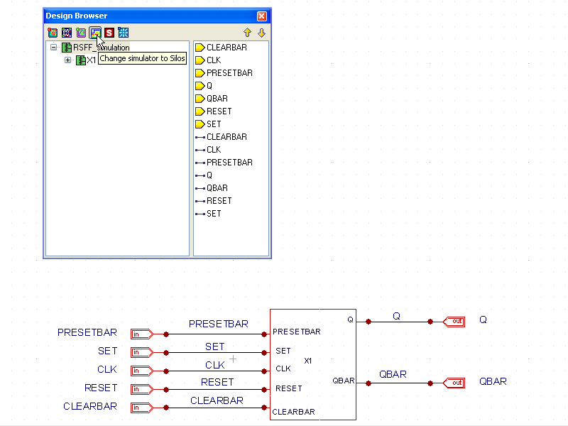
The Gateway schematic front end can capture digital circuits for netlisting in the verilog format and simulating in the Silvaco SILOS simulator. To set Gateway for verilog netlisting, either change the simulator options in the preferences, or click on the SILOS button in the Design Browser window (see window.png ).
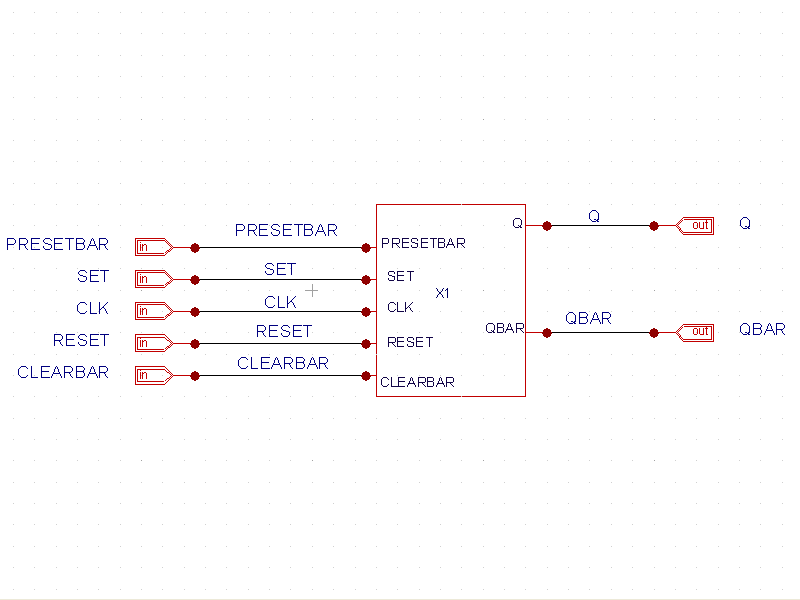
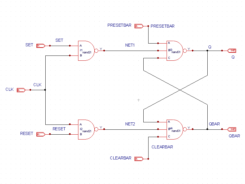
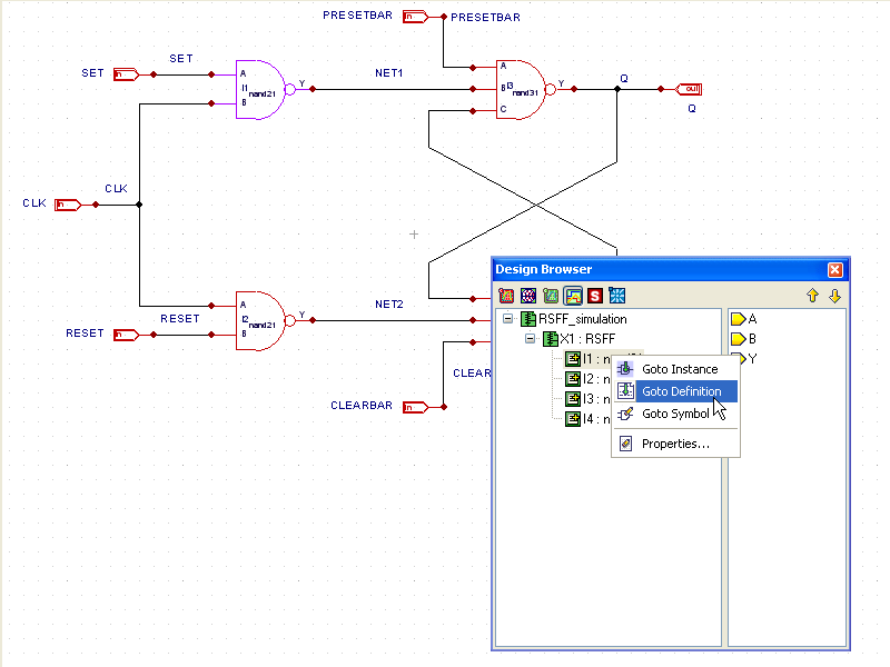
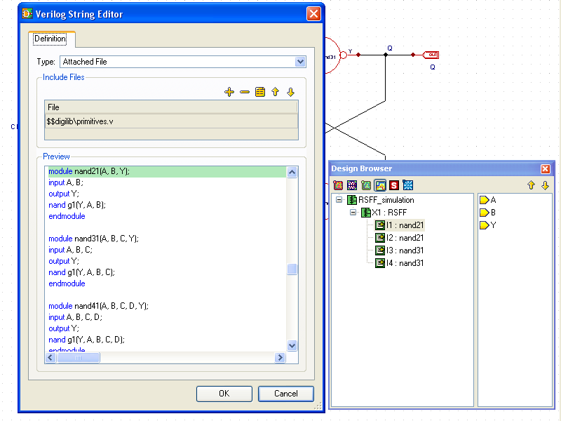
The top level of the RSFF simulation schematic ( RSFF_simulation.png ) is shown as a block level device under test named X1. Descending below X1 reveals the design schematic ( RSFF.png ) which shows the NAND2 and NAND3 instances. On this level, the tree in the design browser shows the four instances by name. The instances in the design browser also provide a way to navigate to the symbol master for editing, or for editing the instance itself. Right clicking on the instance in the design browser reveals the options ( instance.png ). In this case, the icons show a text file with a plus sign, denoting that the module definition for these cells come from an attached file. Clicking the Goto Definition in the menu opens the module definition for the cell ( module_definition.png ).
At this point, the schematic can be checked and then netlisted. When the simulator is set to SILOS, Gateway generates verilog netlists with a *.v file extension. Clicking on the netlist button on the toolbar generates the netlist file ( RSFF_simulation.v). Also, when SILOS is set as the simulator, the control files have a *.ctrv file extension to designate that the test bench is verilog. For this example, clicking on the control file icon shows the verilog test bench in the control file ( RSFF_simulation.ctrv). At the beginning of this file, a clock generator module is included in the stimulus module for generating the pulses required to stimulate the device under test. When SILOS is set as the simulator, Gateway generates *.cfv files as input files for SILOS to use. These files contain library and module input file information required for the project for SILOS. Finally, Gateway also generates a *.spj SILOS project file when the input file is generated. That project file can then be run in the SILOS application interactively and separately from Gateway, if desired. The configuration file ( RSFF_simulation.cfv) and project file ( RSFF_simulation.spj) for this example are displayed.
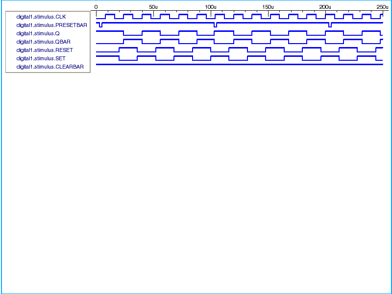
After the simulation, nodes of interest are shown in the SmartView waveform viewer ( smartview.png ).
RSFF_simulation.v
											// Gateway 2.12.10.R Verilog Netlist Generator
// Workspace name:       Q:\examples\gateway\web\design_examples\digital\001_RSFF_sim\RSFF.workspace
// Simulation name:      Q:\examples\gateway\web\design_examples\digital\001_RSFF_sim\RSFF_simulation.schlr
// Simulation timestamp: 07-Jul-2010 11:45:11

// Schematic name: RSFF_simulation
module RSFF_simulation(CLEARBAR, CLK, PRESETBAR, RESET, SET, Q, QBAR);
input CLEARBAR;
input CLK;
input PRESETBAR;
input RESET;
input SET;
output Q;
output QBAR;
wire CLEARBAR;
wire CLK;
wire PRESETBAR;
wire Q;
wire QBAR;
wire RESET;
wire SET;
RSFF X1 (.CLEARBAR(CLEARBAR), .CLK(CLK), .PRESETBAR(PRESETBAR), .RESET(RESET), .SET(SET), .Q(Q), .QBAR(QBAR));
endmodule

// Schematic name: RSFF
module RSFF(CLEARBAR, CLK, PRESETBAR, RESET, SET, Q, QBAR);
input CLEARBAR;
input CLK;
input PRESETBAR;
input RESET;
input SET;
output Q;
output QBAR;
wire CLEARBAR;
wire CLK;
wire NET1;
wire NET2;
wire PRESETBAR;
wire Q;
wire QBAR;
wire RESET;
wire SET;
nand21 I1 (.A(SET), .B(CLK), .Y(NET1));
nand21 I2 (.A(CLK), .B(RESET), .Y(NET2));
nand31 I3 (.A(PRESETBAR), .B(NET1), .C(QBAR), .Y(Q));
nand31 I4 (.A(Q), .B(NET2), .C(CLEARBAR), .Y(QBAR));
endmodule

// End of the netlist
RSFF_simulation.ctrv
											`timescale 1u / 10p
`include "../../libraries/digilib/clk_gen.v"
module stimulus;
wire CLK;
wire PRESETBAR;
wire Q;
wire QBAR;
wire RESET;
wire SET;
reg CLEARBAR;
clk_gen #(.PW(16), .PER(32), .POL(0), .TD(20)) IRESET (.PLUS(RESET));
clk_gen #(.PW(16), .PER(32), .POL(1), .TD(20)) ISET (.PLUS(SET));
clk_gen #(.PW(2), .PER(100), .POL(1), .TD(3)) IPRESETBAR (.PLUS(PRESETBAR));
clk_gen #(.PW(8), .PER(16), .POL(1), .TD(0)) ICLK (.PLUS(CLK));
RSFF_simulation X1( .CLEARBAR(CLEARBAR), .CLK(CLK), .PRESETBAR(PRESETBAR), .Q(Q), .QBAR(QBAR), .RESET(RESET), .SET(SET));
// Code segment for CODE1
initial begin
CLEARBAR=1;
#250 $finish;
end
endmodule
RSFF_simulation.cfv
											// Gateway generated CFV file
// Libraries
-v "Q:\\examples\\gateway\\web\\libraries\\digilib\\primitives.v"
// Log Files
-l "Q:\\examples\\gateway\\web\\design_examples\\digital\\001_RSFF_sim\\RSFF_simulation.log"
// Base name
-"!file .sav=\"RSFF_simulation1\""
// Control options
-"!control .savsim=3"
-"!control .savams=1"
-"!control .savcell=1"
// Input Files
"Q:\\examples\\gateway\\web\\design_examples\\digital\\001_RSFF_sim\\RSFF_simulation.v"
"Q:\\examples\\gateway\\web\\design_examples\\digital\\001_RSFF_sim\\RSFF_simulation.ctrv"
// Run simulation
-"!sim"
RSFF_simulation.spj
											[Files]
0="Q:\examples\gateway\web\design_examples\digital\001_RSFF_sim\RSFF_simulation.v"
1="Q:\examples\gateway\web\design_examples\digital\001_RSFF_sim\RSFF_simulation.ctrv"
[LibraryFiles]
0="Q:\examples\gateway\web\libraries\digilib\primitives.v"


