001_RSFF_sim : RS Flip Flop Simulation
Minimum Required Versions: Gateway 2.12.8.R, SmartSpice 3.16.11.R
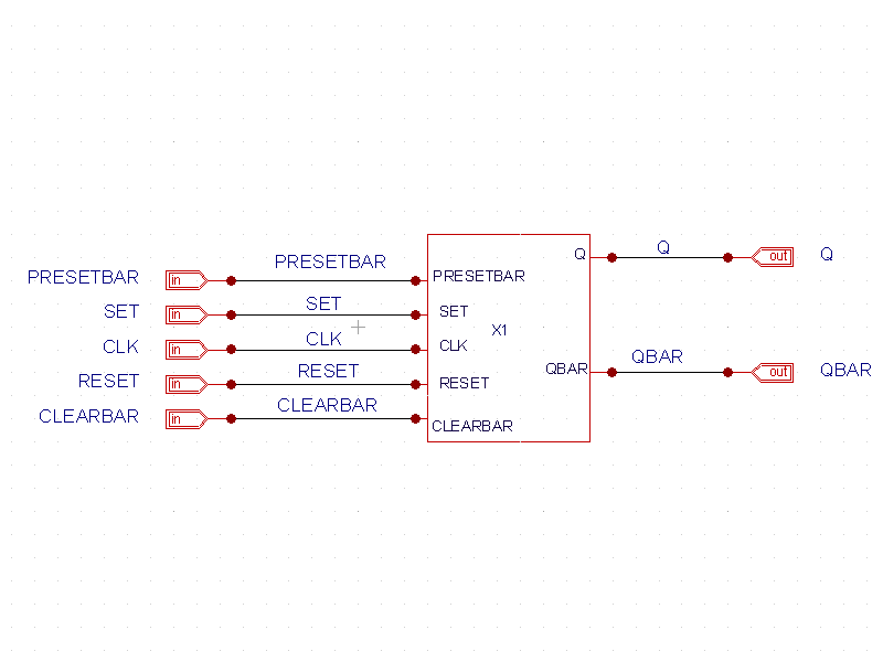
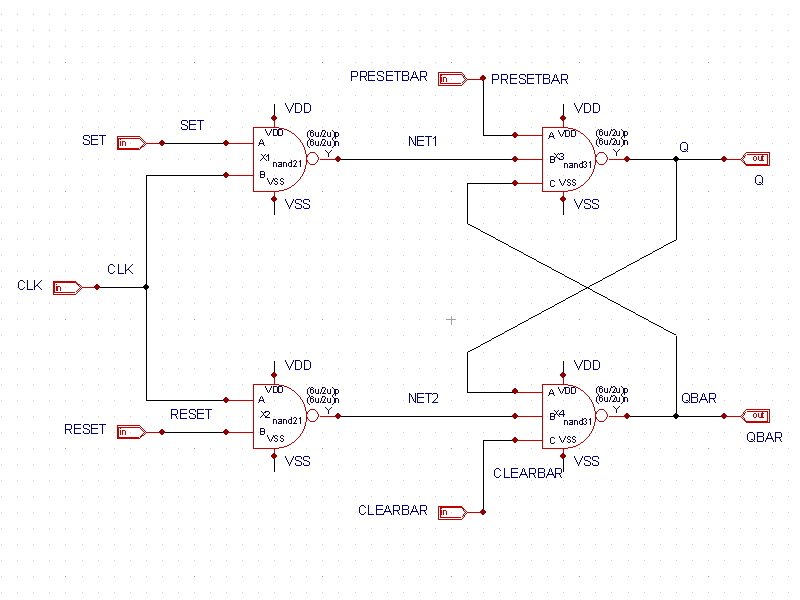
This RSFF simulation is designed hierarchically with the RSFF block sitting on the top level schematic. Descending one level down, the main flip-flop circuit is designed showing the 2 and 3-input NAND gates as the building blocks. Each NAND gate symbol may be further descended down to the cmos primitive schematic level.
The schematic (see top_level_schematic.png ) shows the RSFF block and the pinouts to the test bench.
The schematic RSFF.png contains the NAND gate circuitry that builds the device.
The control file RSFF_simulation.ctris a SPICE file containing the test bench of SPICE statements, options, and models required to run ths simulation.
The input deck RSFF_simulation.inis also a SPICE file and is generated by Gateway from the schematic. Gateway takes the control file and the netlist file to generate an input deck file. This input deck also includes information on specific voltages, currents, and vector data to be saved by the cross probes that are dropped on the schematic.
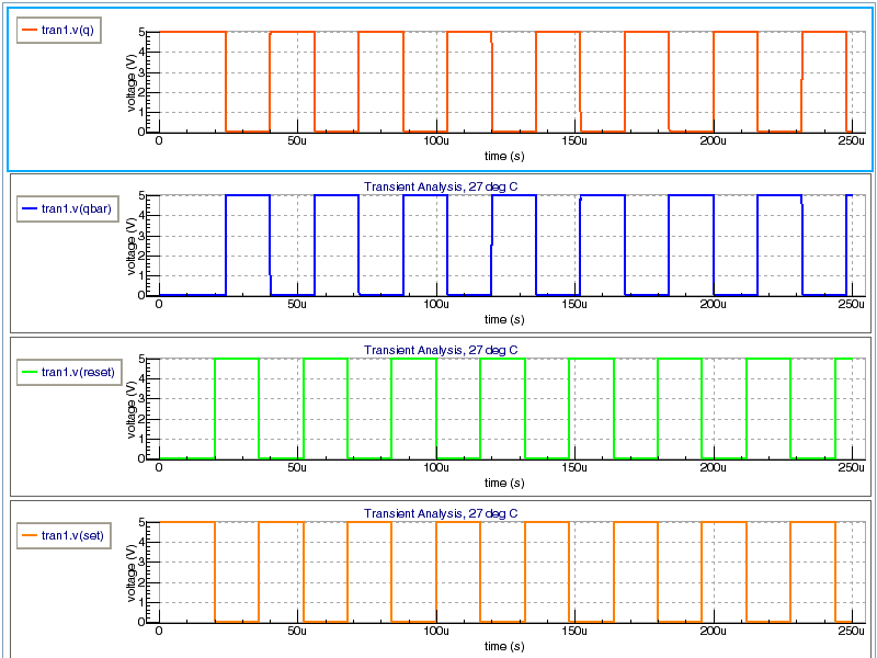
To run the simulation, press the run button. When the simulation completes, the resulting waveforms (see waveforms.png ) are shown in SmartView for postprocessing.
RSFF_simulation.ctr
											************* RSFF SIM - TRANSISTOR LEVEL ***********
*
*
**** MODEL CARDS******
.MODEL NCH NMOS LEVEL=3 PHI=0.700000 TOX=3.0800E-08 XJ=0.200000U TPG=1
+ VTO=0.6897 DELTA=0.0000E+00 LD=1.0250E-07 KP=7.5319E-05
+ UO=671.8 THETA=9.0430E-02 RSH=2.5430E+01 GAMMA=0.7848
+ NSUB=2.3320E+16 NFS=5.9080E+11 VMAX=2.0730E+05 ETA=1.1260E-01
+ KAPPA=3.1050E-01 CGDO=1.7238E-10 CGSO=1.7238E-10
+ CGBO=5.1091E-10 CJ=2.8806E-04 MJ=5.1398E-01 CJSW=1.4678E-10
+ MJSW=1.0000E-01 PB=9.9000E-01
*
.MODEL PCH PMOS LEVEL=3 PHI=0.700000 TOX=3.0800E-08 XJ=0.200000U TPG=-1
+ VTO=-0.7574 DELTA=2.9770E+00 LD=9.8570E-08 KP=2.1492E-05
+ UO=191.7 THETA=1.2020E-01 RSH=3.5220E+00 GAMMA=0.4112
+ NSUB=6.4040E+15 NFS=3.5000E+11 VMAX=2.6200E+05 ETA=1.4820E-01
+ KAPPA=1.0000E+01 CGDO=1.6577E-10 CGSO=1.6577E-10
+ CGBO=4.2561E-10 CJ=2.9897E-04 MJ=4.3307E-01 CJSW=1.8038E-10
+ MJSW=1.4701E-01 PB=7.3950E-01
*
*
*
**** ANALYSIS *****
.TRAN 1u 250u
*

***** INPUTS

CLOAD_Q Q GND 5P
CLOAD_QB QBAR GND 5P
VCLEARBAR CLEARBAR GND DC 5
VCLK CLK GND PULSE(5 0 0 5N 5N 8U 16U)
VDD VDD GND DC 5
VPRESETBAR PRESETBAR GND PULSE(5 0 3U 5N 5N 2U )
VRESET RESET GND PULSE(0 5 20u 5N 5N 16u 32u)
VSET SET GND PULSE(5 0 20u 5N 5N 16u 32u)
VSS VSS GND DC 0
*
**** OPTIONS *****
.OPTIONS acct=2
.GLOBAL VDD VSS GND
RSFF_simulation.in
											* Q:\examples\gateway\web\design_examples\analog\001_RSFF_sim\RSFF_simulation
* Gateway 2.12.7.R Spice Netlist Generator
* Workspace name:       Q:\examples\gateway\web\design_examples\analog\001_RSFF_sim\RSFF.workspace
* Simulation name:      Q:\examples\gateway\web\design_examples\analog\001_RSFF_sim\RSFF_simulation.schlr
* Simulation timestamp: 05-May-2010 10:35:53

* Schematic name: RSFF_simulation
X1 CLEARBAR CLK PRESETBAR RESET SET Q QBAR RSFF

* Schematic name: RSFF
.SUBCKT RSFF CLEARBAR CLK PRESETBAR RESET SET Q QBAR
X1 SET CLK NET1 VDD VSS nand21 PARAMS: LN=2u LP=2u WN=6u WP=6u
X2 CLK RESET NET2 VDD VSS nand21 PARAMS: LN=2u LP=2u WN=6u WP=6u
X3 PRESETBAR NET1 QBAR Q VDD VSS nand31 PARAMS: LN=2u LP=2u WN=6u WP=6u
X4 Q NET2 CLEARBAR QBAR VDD VSS nand31 PARAMS: LN=2u LP=2u WN=6u WP=6u
.ENDS RSFF

* Schematic name: nand21
.SUBCKT nand21 A B Y VDD VSS
M1 Y A VDD VDD PCH L=LP W=WP
M2 Y B VDD VDD PCH L=LP W=WP
M3 Y A NET1 VSS NCH L=LN W=WN
M4 NET1 B VSS VSS NCH L=LN W=WN
.ENDS nand21

* Schematic name: nand31
.SUBCKT nand31 A B C Y VDD VSS
M1 Y C VDD VDD PCH L=LP W=WP
M2 Y A NET2 VSS NCH L=LN W=WN
M3 NET2 B NET1 VSS NCH L=LN W=WN
M4 Y A VDD VDD PCH L=LP W=WP
M5 Y B VDD VDD PCH L=LP W=WP
M6 NET1 C VSS VSS NCH L=LN W=WN
.ENDS nand31

* Global Nodes Declarations
.GLOBAL GND VDD VSS

* End of the netlist

*
* Markers to save
*
.SAVE V(Q) V(QBAR) V(RESET) V(SET)

* Schematic Netlist rebuilt at runtime

************* RSFF SIM - TRANSISTOR LEVEL ***********
*
*
**** MODEL CARDS******
.MODEL NCH NMOS LEVEL=3 PHI=0.700000 TOX=3.0800E-08 XJ=0.200000U TPG=1
+ VTO=0.6897 DELTA=0.0000E+00 LD=1.0250E-07 KP=7.5319E-05
+ UO=671.8 THETA=9.0430E-02 RSH=2.5430E+01 GAMMA=0.7848
+ NSUB=2.3320E+16 NFS=5.9080E+11 VMAX=2.0730E+05 ETA=1.1260E-01
+ KAPPA=3.1050E-01 CGDO=1.7238E-10 CGSO=1.7238E-10
+ CGBO=5.1091E-10 CJ=2.8806E-04 MJ=5.1398E-01 CJSW=1.4678E-10
+ MJSW=1.0000E-01 PB=9.9000E-01
*
.MODEL PCH PMOS LEVEL=3 PHI=0.700000 TOX=3.0800E-08 XJ=0.200000U TPG=-1
+ VTO=-0.7574 DELTA=2.9770E+00 LD=9.8570E-08 KP=2.1492E-05
+ UO=191.7 THETA=1.2020E-01 RSH=3.5220E+00 GAMMA=0.4112
+ NSUB=6.4040E+15 NFS=3.5000E+11 VMAX=2.6200E+05 ETA=1.4820E-01
+ KAPPA=1.0000E+01 CGDO=1.6577E-10 CGSO=1.6577E-10
+ CGBO=4.2561E-10 CJ=2.9897E-04 MJ=4.3307E-01 CJSW=1.8038E-10
+ MJSW=1.4701E-01 PB=7.3950E-01
*
*
*
**** ANALYSIS *****
.TRAN 1u 250u
*

***** INPUTS

CLOAD_Q Q GND 5P
CLOAD_QB QBAR GND 5P
VCLEARBAR CLEARBAR GND DC 5
VCLK CLK GND PULSE(5 0 0 5N 5N 8U 16U)
VDD VDD GND DC 5
VPRESETBAR PRESETBAR GND PULSE(5 0 3U 5N 5N 2U )
VRESET RESET GND PULSE(0 5 20u 5N 5N 16u 32u)
VSET SET GND PULSE(5 0 20u 5N 5N 16u 32u)
VSS VSS GND DC 0
*
**** OPTIONS *****
.OPTIONS acct=2
.GLOBAL VDD VSS GND

.END


