008_sdl : Schematic Driven Layout (SDL) flow with Gateway
Minimum Required Versions: Expert 4.10.39.R & Gateway 2.12.32.R
Expert Schematic Driven Layout (SDL) tool increases the productivity of layout design by automating cell generation and providing visual cues to assist the wiring process. The SDL is used to automatically create IC layouts based on the information from a SPICE netlist. Cell instances are created from existing cells. PCells are instantiated with parameters from the SPICE netlist. The SDL automatically transfers net names, instance names and connectivity information from the SPICE netlist to the layout.
1.1. Create the SPICE netlist from Gateway
Gateway creates the SPICE netlist for SDL after making the circuit. It is necessary to allocate the device name of the circuit to the model name of SPICE. In Gateway, the associated SPICE netlist can be created by using the Control Cards ( ex012_ndl.ctr).
In order to create the SPICE netlist of SDL, select Layout->Netlist->NDL from the Gateway menu.
1.2. Load the SPICE netlist to Expert
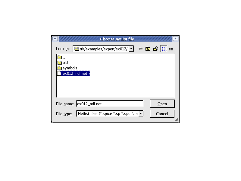
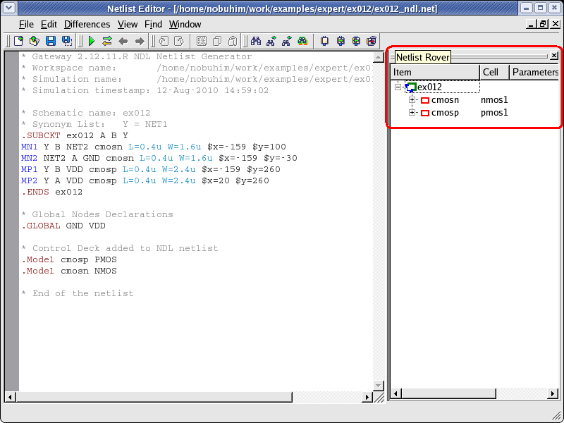
The SPICE netlist is loaded by selecting Tools->Netlist Driven Layout->Load Netlist from the Expert menu. The window will be opened to select the SPICE netlist (see choose_netlist_dlg.png ). After you select the SPICE netlist and click the Open button, the Netlist Editor window will open. It displays the SPICE netlist and the Netlist Rover, which helps you browse through the netlist hierarchy (see netlist_rover.png ).
1.3. Create Cells
When the device name is different between the circuit and the layout, a device mapping file must be provided ( ex012.map). The device mapping file can be read by selecting File->Load Map from the Netlist Editor. The cell name is then added in the Netlist Rover (see netlist_mapping.png ).
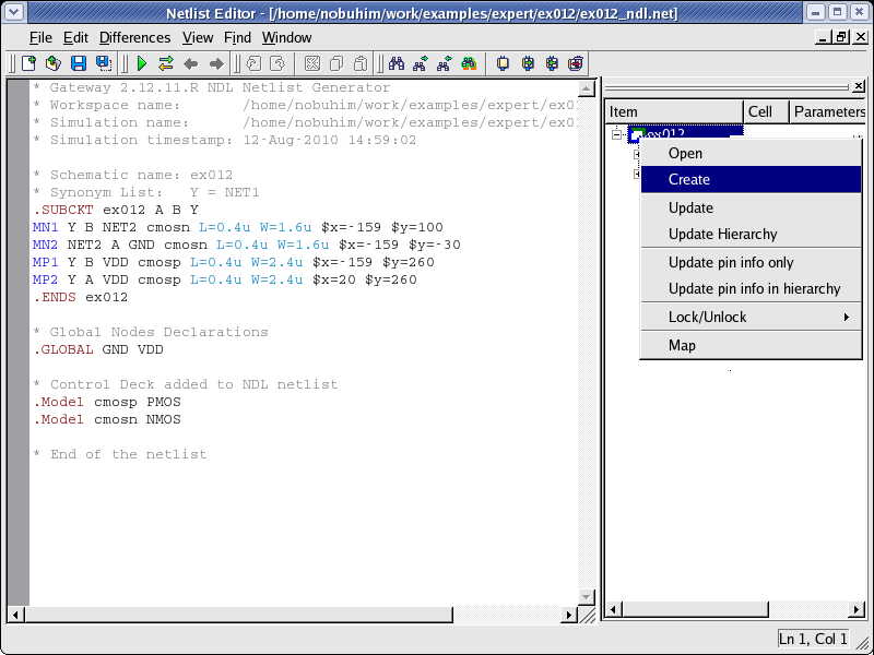
The layout cell can be created using the Netlist Rover by following these steps:
- Select the cell name
- Click the right mouse button to open a popup menu
- Select "Create" in the popup menu (see popup_menu.png ).
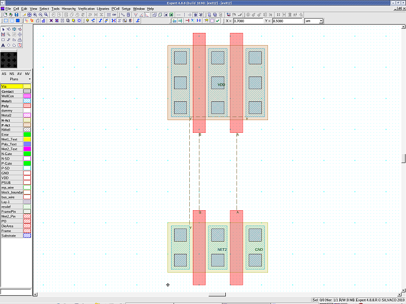
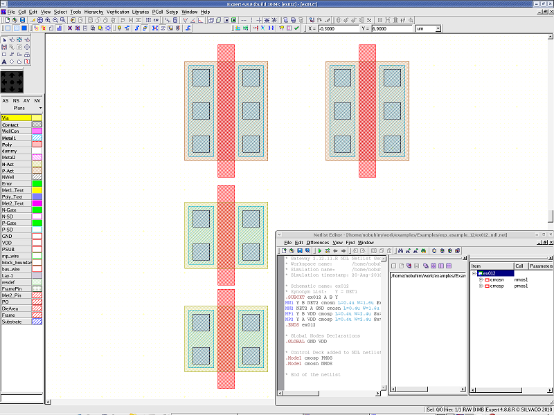
- The instances are placed in the layout cell (see placement.png )
1.4. Layout Editing
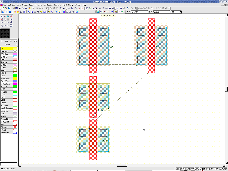
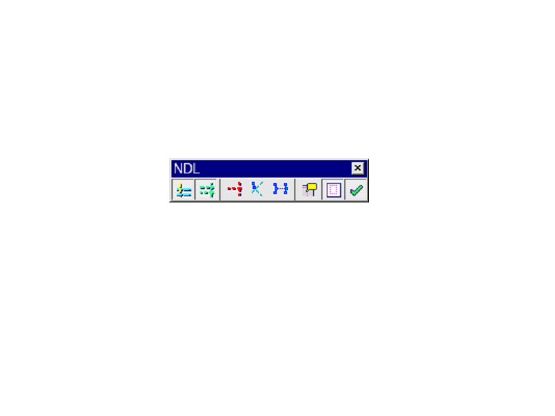
In order to help in the layout editing task, display the flight lines (wiring information) using the NDL toolbar. The NDL toolbar can be displayed by selecting View->Toolbars->NDL (see ndl_toolbar.png ).
When the first icon to the left on the NDL toolbar is clicked, the flight lines of the net, other than global nets, are displayed.
When the second icon is pressed, the global nets are displayed (see flight_line.png
).
As the placement of the instances is changed during the layout editing task, the flight lines follow the new location (see modify_placement.png
).
1.5. Cross Probing
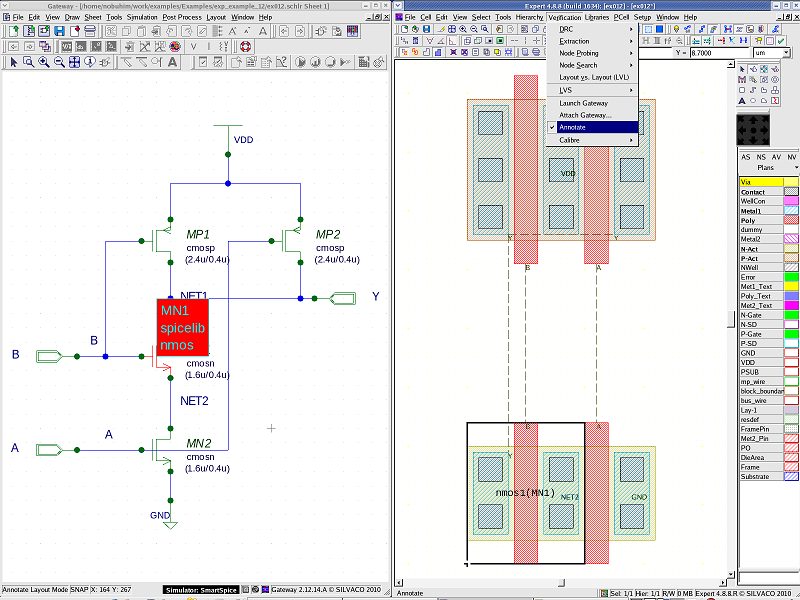
The cross probing can be performed between Gateway (Schematic) and Expert (Layout). The instance in the layout can be highligthed by clicking on a symbol in the schematic and vice versa. In order to allow the cross probing to work properly it is necessary to launch Gateway from within Expert by selecting Verification->Launch Gateway .
After the schematic is opened in Gateway, the Annotate command is turned on by selecting Verification->Annotate . The Cross Probing is then executed by selecting the symbol in the schematic or the instance in the layout (see cross_probing.png ).
1.6. Layout Routing
The routing task is being completed by simply making the connections indicated by the flight lines. Many routing mistakes can be avoided by following the flight line guidance during the layout task.
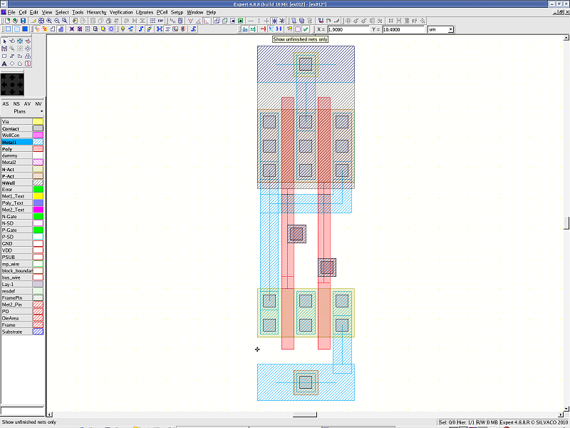
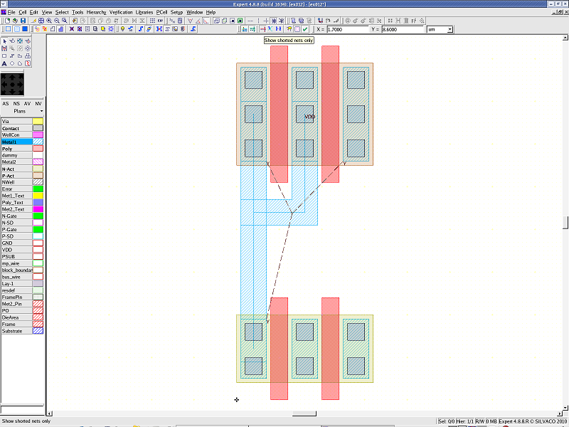
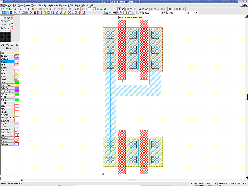
When the routing is completed, it must be checked using the Shorted nets command and the Unfinished nets command from the NDL toolbar. The Shorted nets command displays the nets in red (see shorted_net.png ). The Unfinished nets command only displays the unfinished nets, in other words, the flight lines of the finished routing nets are not displayed (see unfinished_net.png ). On completion of the layout, if the Unfinished nets command is used, none of the flight lines should be displayed. (See finished_net.png ).
ex012.map
											cmosp	pmos1
cmosn	nmos1
ex012_ndl.ctr
											.Model cmosp PMOS
.Model cmosn NMOS
ex012_ndl.net
											* Gateway 2.12.11.R NDL Netlist Generator
* Workspace name:       /home/nobuhim/work/examples/Expert_examples/exp_example_12/ex012.workspace
* Simulation name:      /home/nobuhim/work/examples/Expert_examples/exp_example_12/ex012.schlr
* Simulation timestamp: 13- 8月-2010 09:14:46

* Schematic name: ex012
* Synonym List:   Y = NET1
.SUBCKT ex012 A B Y
MN1 Y B NET2 cmosn L=0.4u W=1.6u $x=-159 $y=100
MN2 NET2 A GND cmosn L=0.4u W=1.6u $x=-159 $y=-30
MP1 Y B VDD cmosp L=0.4u W=2.4u $x=-159 $y=260
MP2 Y A VDD cmosp L=0.4u W=2.4u $x=20 $y=260
.ENDS ex012

* Global Nodes Declarations
.GLOBAL GND VDD

* Control Deck added to NDL netlist
.Model cmosp PMOS
.Model cmosn NMOS

* End of the netlist