 https://silvaco.com/wp-content/uploads/simulationstandard/simstd_may_2005_a2-e1611194725980.jpg
800
644
Erick Castellon
/wp-content/uploads/2019/11/silvaco-logo.png
Erick Castellon2005-05-01 00:02:212021-10-13 10:35:28Simulating the Device Characteristics of MEH-PPV Polymer Light Emitting Diodes Using Atlas
https://silvaco.com/wp-content/uploads/simulationstandard/simstd_may_2005_a2-e1611194725980.jpg
800
644
Erick Castellon
/wp-content/uploads/2019/11/silvaco-logo.png
Erick Castellon2005-05-01 00:02:212021-10-13 10:35:28Simulating the Device Characteristics of MEH-PPV Polymer Light Emitting Diodes Using Atlas https://silvaco.com/wp-content/uploads/simulationstandard/simstd_may_2005_a1-e1611193337157.jpg
800
600
Erick Castellon
/wp-content/uploads/2019/11/silvaco-logo.png
Erick Castellon2005-05-01 00:01:122021-10-13 10:35:28A Comprehensive Solution for Simulating Ultra-Shallow Junctions: From High Dose/Low Energy Implant to Diffusion Annealing
https://silvaco.com/wp-content/uploads/simulationstandard/simstd_may_2005_a1-e1611193337157.jpg
800
600
Erick Castellon
/wp-content/uploads/2019/11/silvaco-logo.png
Erick Castellon2005-05-01 00:01:122021-10-13 10:35:28A Comprehensive Solution for Simulating Ultra-Shallow Junctions: From High Dose/Low Energy Implant to Diffusion Annealing https://silvaco.com/wp-content/uploads/simulationstandard/simstd_mar_2005_a4-e1611193543229.jpg
800
644
Erick Castellon
/wp-content/uploads/2019/11/silvaco-logo.png
Erick Castellon2005-03-01 00:05:562021-10-13 10:35:28Expert: Wiring
https://silvaco.com/wp-content/uploads/simulationstandard/simstd_mar_2005_a4-e1611193543229.jpg
800
644
Erick Castellon
/wp-content/uploads/2019/11/silvaco-logo.png
Erick Castellon2005-03-01 00:05:562021-10-13 10:35:28Expert: Wiring https://silvaco.com/wp-content/uploads/simulationstandard/simstd_mar_2005_hints-e1611194144182.jpg
800
644
Erick Castellon
/wp-content/uploads/2019/11/silvaco-logo.png
Erick Castellon2005-03-01 00:05:002021-10-13 10:35:47I have to send copies of my project layout to different members of my group
https://silvaco.com/wp-content/uploads/simulationstandard/simstd_mar_2005_hints-e1611194144182.jpg
800
644
Erick Castellon
/wp-content/uploads/2019/11/silvaco-logo.png
Erick Castellon2005-03-01 00:05:002021-10-13 10:35:47I have to send copies of my project layout to different members of my group https://silvaco.com/wp-content/uploads/simulationstandard/simstd_mar_2005_a3.jpg
1669
1344
Erick Castellon
/wp-content/uploads/2019/11/silvaco-logo.png
Erick Castellon2005-03-01 00:04:562021-10-13 10:35:48Expert: Layout Versus Layout (LVL) Comparison
https://silvaco.com/wp-content/uploads/simulationstandard/simstd_mar_2005_a3.jpg
1669
1344
Erick Castellon
/wp-content/uploads/2019/11/silvaco-logo.png
Erick Castellon2005-03-01 00:04:562021-10-13 10:35:48Expert: Layout Versus Layout (LVL) Comparison https://silvaco.com/wp-content/uploads/simulationstandard/simstd_mar_2005_a2.jpg
1669
1344
Erick Castellon
/wp-content/uploads/2019/11/silvaco-logo.png
Erick Castellon2005-03-01 00:02:252021-10-13 10:35:48New Parasitic Capacitance Modeling in Hipex-C
https://silvaco.com/wp-content/uploads/simulationstandard/simstd_mar_2005_a2.jpg
1669
1344
Erick Castellon
/wp-content/uploads/2019/11/silvaco-logo.png
Erick Castellon2005-03-01 00:02:252021-10-13 10:35:48New Parasitic Capacitance Modeling in Hipex-C https://silvaco.com/wp-content/uploads/simulationstandard/simstd_mar_2005_a1.jpg
1669
1252
Erick Castellon
/wp-content/uploads/2019/11/silvaco-logo.png
Erick Castellon2005-03-01 00:01:232021-10-13 10:35:48Capacitance Coupling Calculation of IPS mode TFT-LCD Using Clever
https://silvaco.com/wp-content/uploads/simulationstandard/simstd_mar_2005_a1.jpg
1669
1252
Erick Castellon
/wp-content/uploads/2019/11/silvaco-logo.png
Erick Castellon2005-03-01 00:01:232021-10-13 10:35:48Capacitance Coupling Calculation of IPS mode TFT-LCD Using Clever https://silvaco.com/wp-content/uploads/simulationstandard/simstd_feb_2005_hints.jpg
1669
1344
Erick Castellon
/wp-content/uploads/2019/11/silvaco-logo.png
Erick Castellon2005-02-01 00:05:332021-10-13 10:35:48Can Athena get the STRESS in Compound Advanced material?
https://silvaco.com/wp-content/uploads/simulationstandard/simstd_feb_2005_hints.jpg
1669
1344
Erick Castellon
/wp-content/uploads/2019/11/silvaco-logo.png
Erick Castellon2005-02-01 00:05:332021-10-13 10:35:48Can Athena get the STRESS in Compound Advanced material?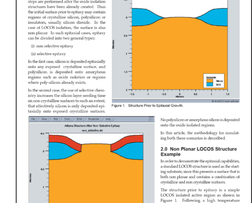 https://silvaco.com/wp-content/uploads/simulationstandard/simstd_feb_2005_a3.jpg
1669
1344
Erick Castellon
/wp-content/uploads/2019/11/silvaco-logo.png
Erick Castellon2005-02-01 00:04:242021-10-13 10:35:56Simulating Selective and Non-Selective Epitaxy Over Oxide Isolated Regions Using Athena
https://silvaco.com/wp-content/uploads/simulationstandard/simstd_feb_2005_a3.jpg
1669
1344
Erick Castellon
/wp-content/uploads/2019/11/silvaco-logo.png
Erick Castellon2005-02-01 00:04:242021-10-13 10:35:56Simulating Selective and Non-Selective Epitaxy Over Oxide Isolated Regions Using Athena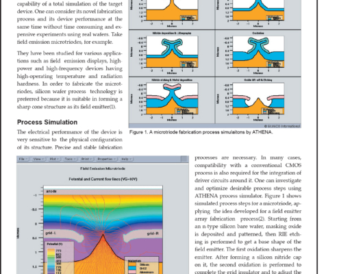 https://silvaco.com/wp-content/uploads/simulationstandard/simstd_feb_2005_a2-e1611193488403.jpg
800
644
Erick Castellon
/wp-content/uploads/2019/11/silvaco-logo.png
Erick Castellon2005-02-01 00:02:112021-10-13 10:35:56Process and Device Simulation of Field Emission Microtrides
https://silvaco.com/wp-content/uploads/simulationstandard/simstd_feb_2005_a2-e1611193488403.jpg
800
644
Erick Castellon
/wp-content/uploads/2019/11/silvaco-logo.png
Erick Castellon2005-02-01 00:02:112021-10-13 10:35:56Process and Device Simulation of Field Emission Microtrides