Hints, Tips and Solutions – May 2004
Q. When solving for the static CV curve for a MOS capacitor, due to the absence of current carriers, convergence can be a real problem. Previous methods suggested in the hints and tips archive of Silvaco’s simulation standard have made use of Silvaco’s Luminous module where a small amount of light intensity is incident on the device, the idea being to generate a small amount of carriers to aid convergence.
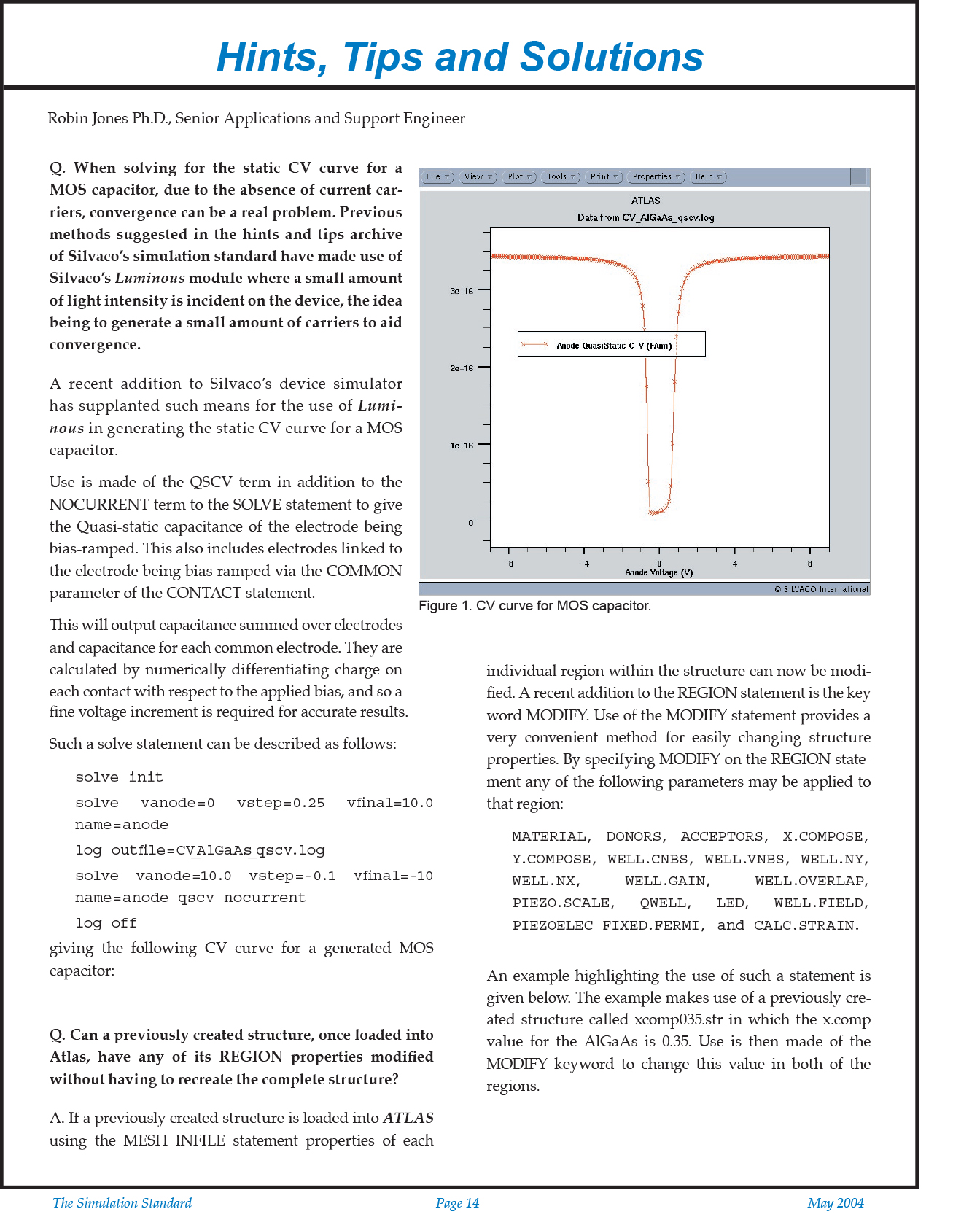
A. A recent addition to Silvaco’s device simulator has supplanted such means for the use of Luminous in generating the static CV curve for a MOS capacitor.
Use is made of the QSCV term in addition to the NOCURRENT term to the SOLVE statement to give the Quasi-static capacitance of the electrode being bias-ramped. This also includes electrodes linked to the electrode being bias ramped via the COMMON parameter of the CONTACT statement.
This will output capacitance summed over electrodes and capacitance for each common electrode. They are calculated by numerically differentiating charge on each contact with respect to the applied bias, and so a fine voltage increment is required for accurate results.
Such a solve statement can be described as follows:
solve init
solve vanode=0 vstep=0.25 vfinal=10.0 name=anode
log outfile=CV_AlGaAs_qscv.log
solve vanode=10.0 vstep=-0.1 vfinal=-10 name=anode qscv nocurrent
log off
giving the following CV curve for a generated MOS capacitor:
Q. Can a previously created structure, once loaded into Atlas, have any of its REGION properties modified without having to recreate the complete structure?
A. If a previously created structure is loaded into ATLAS using the MESH INFILE statement properties of each individual region within the structure can now be modified. A recent addition to the REGION statement is the key word MODIFY. Use of the MODIFY statement provides a very convenient method for easily changing structure properties. By specifying MODIFY on the REGION statement any of the following parameters may be applied to that region:
MATERIAL, DONORS, ACCEPTORS, X.COMPOSE, Y.COMPOSE, WELL.CNBS, WELL.VNBS, WELL.NY, WELL.NX, WELL.GAIN, WELL.OVERLAP, PIEZO.SCALE, QWELL, LED, WELL.FIELD, PIEZOELEC FIXED.FERMI, and CALC.STRAIN.
An example highlighting the use of such a statement is given below. The example makes use of a previously created structure called xcomp035.str in which the x.comp value for the AlGaAs is 0.35. Use is then made of the MODIFY keyword to change this value in both of the regions.
Figure 2 shows the before and after structure property of the x.comp parameter obtained by taking a one dimensional cut line through the structure in TonyPlot. Use of the MODIFY statement provides a very convenient method for easily changing structure properties.


