HiSIM-1.2 Parameter Extraction with the Revised UTMOST-III Local Optimization Strategies
1. Introduction
HiSIM-1.2 parameter extraction methodology was discussed in detail in a previous issue of Silvaco Simulation Standard [1]. This article is meant to provide the precise UTMOST-III local optimization strategies to UTMOST-III users who are interested in HiSIM-1.2 parameter extraction. The developed strategies were applied to the actual 90 nm technology devices [2]. The HiSIM-1.2 proved the capability to give the scalable model down to 100 nm from 10 um channel length with no parameter binning.
HiSIM-1.2 model parameters [3] are capitalized with the bold letters in this article.
2. Required Geometries for the Parameter Optimization
As the HiSIM model is based on the device physics [3], the geometry selection is quite significant to obtain the scalable parameter set. Large device with the long and wide channel is the starting point. Then, the length array(L-array) devices with the varied channel lengths under the fixed width should be prepared, preferably under the wide width, if the width dependent leakage current such as due to a shallow trench isolation (STI) isn’t prominent. The channel length spacing should be small enough to represent the channel length effects such as a reverse short channel (RSC) and a short channel (SC) effects. The HiSIM-1.2 RSC and SC parameter extractions are found to require the threshold voltage dependency on the channel length, even though no explicit threshold voltage parameter is used in HiSIM-1.2 [1].
The width array (W-array) devices with the varied channel widths under the fixed length are also necessary. The small devices are used for the model verification, not for the parameter extractions. Neither dedicated parameters for small devices nor the parameter binning are defined in HiSIM-1.2.
3. Required Current Voltage Characteristics
Id/Vg at several drain voltages with the varied body biases should be measured. The drain voltages should cover the low linear, the linear to the saturation transition and the saturation regions. Id/Vd at several body voltages under the operating voltage range are used mainly for the high field mobility tuning. Most of HiSIM-1.2 parameter extractions are done with Id/Vg curves.
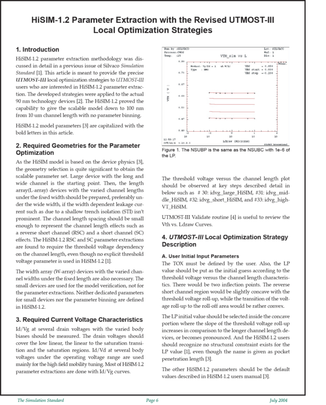
The threshold voltage versus the channel length plot should be observed at key steps described detail in below such as # 30: idvg_large_HiSIM, #31: idvg_middle_HiSIM, #32: idvg_short_HiSIM, and #33: idvg_highVT_HiSIM.
UTMOST-III Validate routine [4] is useful to review the Vth vs. Ldraw Curves.


