 https://silvaco.com/wp-content/uploads/2020/03/simstd_Q4_2017_a1-1.jpg
1012
782
Ingrid Schwarz
/wp-content/uploads/2019/11/silvaco-logo.png
Ingrid Schwarz2017-10-01 00:03:362021-07-08 18:14:37Automated Stress Simulation Interface Between Victory Process and Device
https://silvaco.com/wp-content/uploads/2020/03/simstd_Q4_2017_a1-1.jpg
1012
782
Ingrid Schwarz
/wp-content/uploads/2019/11/silvaco-logo.png
Ingrid Schwarz2017-10-01 00:03:362021-07-08 18:14:37Automated Stress Simulation Interface Between Victory Process and Device https://silvaco.com/wp-content/uploads/2020/02/simstd_Q4_2017_a2-1.jpg
1012
782
Ingrid Schwarz
/wp-content/uploads/2019/11/silvaco-logo.png
Ingrid Schwarz2017-10-01 00:02:082021-07-08 18:14:38TCAD Simulation of GaN-based Vertical FETs (HEMTs)
https://silvaco.com/wp-content/uploads/2020/02/simstd_Q4_2017_a2-1.jpg
1012
782
Ingrid Schwarz
/wp-content/uploads/2019/11/silvaco-logo.png
Ingrid Schwarz2017-10-01 00:02:082021-07-08 18:14:38TCAD Simulation of GaN-based Vertical FETs (HEMTs) https://silvaco.com/wp-content/uploads/2020/02/simstd_Q3_2017_a1-1.jpg
1012
782
Ingrid Schwarz
/wp-content/uploads/2019/11/silvaco-logo.png
Ingrid Schwarz2017-07-01 23:44:122021-07-08 18:14:38Calculating Failures In Time Rates for FinFET Circuits Using TCAD
https://silvaco.com/wp-content/uploads/2020/02/simstd_Q3_2017_a1-1.jpg
1012
782
Ingrid Schwarz
/wp-content/uploads/2019/11/silvaco-logo.png
Ingrid Schwarz2017-07-01 23:44:122021-07-08 18:14:38Calculating Failures In Time Rates for FinFET Circuits Using TCAD https://silvaco.com/wp-content/uploads/2020/02/simstd_Q3_2017_a2-1.jpg
1012
782
Ingrid Schwarz
/wp-content/uploads/2019/11/silvaco-logo.png
Ingrid Schwarz2017-07-01 23:27:012021-07-08 18:14:52Optical Simulation of Liquid Crystals in the In-plane Switching Mode
https://silvaco.com/wp-content/uploads/2020/02/simstd_Q3_2017_a2-1.jpg
1012
782
Ingrid Schwarz
/wp-content/uploads/2019/11/silvaco-logo.png
Ingrid Schwarz2017-07-01 23:27:012021-07-08 18:14:52Optical Simulation of Liquid Crystals in the In-plane Switching Mode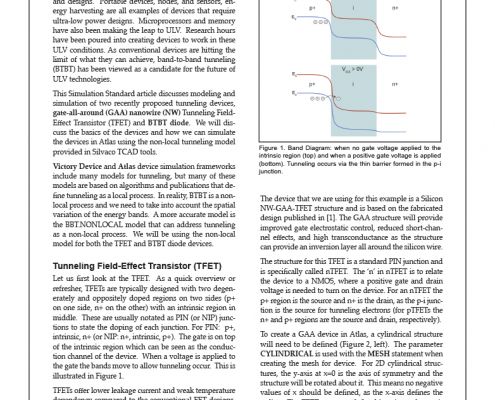 https://silvaco.com/wp-content/uploads/2020/03/simstd_Q3_2017_a3-1.jpg
1012
782
Ingrid Schwarz
/wp-content/uploads/2019/11/silvaco-logo.png
Ingrid Schwarz2017-07-01 22:42:122021-07-08 18:14:52TCAD Simulations of TFET and Tunneling Diode
https://silvaco.com/wp-content/uploads/2020/03/simstd_Q3_2017_a3-1.jpg
1012
782
Ingrid Schwarz
/wp-content/uploads/2019/11/silvaco-logo.png
Ingrid Schwarz2017-07-01 22:42:122021-07-08 18:14:52TCAD Simulations of TFET and Tunneling Diode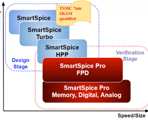 https://silvaco.com/wp-content/uploads/2020/03/TFT_SmartSpice_fig1.jpg
417
550
Ingrid Schwarz
/wp-content/uploads/2019/11/silvaco-logo.png
Ingrid Schwarz2017-07-01 19:44:552021-07-08 18:14:53TFT Panel Simulation Using SmartSpice Pro
https://silvaco.com/wp-content/uploads/2020/03/TFT_SmartSpice_fig1.jpg
417
550
Ingrid Schwarz
/wp-content/uploads/2019/11/silvaco-logo.png
Ingrid Schwarz2017-07-01 19:44:552021-07-08 18:14:53TFT Panel Simulation Using SmartSpice Pro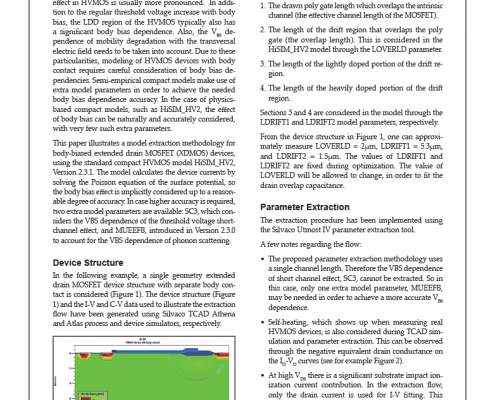 https://silvaco.com/wp-content/uploads/2020/02/simstd_Q2_2017_a4-1.jpg
1012
782
Ingrid Schwarz
/wp-content/uploads/2019/11/silvaco-logo.png
Ingrid Schwarz2017-04-01 18:27:142021-07-08 18:14:53Model Extraction for Body-Biased XDMOS Devices
https://silvaco.com/wp-content/uploads/2020/02/simstd_Q2_2017_a4-1.jpg
1012
782
Ingrid Schwarz
/wp-content/uploads/2019/11/silvaco-logo.png
Ingrid Schwarz2017-04-01 18:27:142021-07-08 18:14:53Model Extraction for Body-Biased XDMOS Devices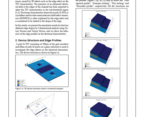 https://silvaco.com/wp-content/uploads/2020/02/simstd_Q2_2017_a3.jpg
1012
782
Ingrid Schwarz
/wp-content/uploads/2019/11/silvaco-logo.png
Ingrid Schwarz2017-04-01 18:23:472021-07-08 18:14:54Edge Effect Analysis on TFT Devices Using 3D Numerical Simulation
https://silvaco.com/wp-content/uploads/2020/02/simstd_Q2_2017_a3.jpg
1012
782
Ingrid Schwarz
/wp-content/uploads/2019/11/silvaco-logo.png
Ingrid Schwarz2017-04-01 18:23:472021-07-08 18:14:54Edge Effect Analysis on TFT Devices Using 3D Numerical Simulation https://silvaco.com/wp-content/uploads/2020/02/simstd_Q2_2017_a2.jpg
1012
782
Ingrid Schwarz
/wp-content/uploads/2019/11/silvaco-logo.png
Ingrid Schwarz2017-04-01 18:17:162021-07-08 18:16:293D Simulation of Dual-Gate Thin Film Transistors
https://silvaco.com/wp-content/uploads/2020/02/simstd_Q2_2017_a2.jpg
1012
782
Ingrid Schwarz
/wp-content/uploads/2019/11/silvaco-logo.png
Ingrid Schwarz2017-04-01 18:17:162021-07-08 18:16:293D Simulation of Dual-Gate Thin Film Transistors https://silvaco.com/wp-content/uploads/2020/02/simstd_Q2_2017_a1.jpg
1012
782
Ingrid Schwarz
/wp-content/uploads/2019/11/silvaco-logo.png
Ingrid Schwarz2017-04-01 18:10:392021-07-08 18:16:29Effect of Fin Thickness on Subthreshold Characteristics of 10 nm FinFETs Using 3D TCAD
https://silvaco.com/wp-content/uploads/2020/02/simstd_Q2_2017_a1.jpg
1012
782
Ingrid Schwarz
/wp-content/uploads/2019/11/silvaco-logo.png
Ingrid Schwarz2017-04-01 18:10:392021-07-08 18:16:29Effect of Fin Thickness on Subthreshold Characteristics of 10 nm FinFETs Using 3D TCAD