I have to send copies of my project layout to different members of my group
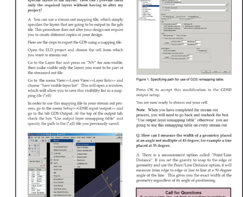
Q. I have to send copies of my project layout to different members of my group, but they need to see only specific layers of the layout. How can I provide them only the required layers without having to alter my project?
Expert: Layout Versus Layout (LVL) Comparison
Introduction
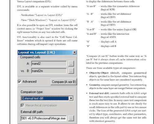
The functionality Silvaco’s Layou Editor, Expert, has recently been expanded with the new feature called Layout Versus Layout comparison (LVL).
LVL is available as a separate window called by menu commands:
New Parasitic Capacitance Modeling in Hipex-C
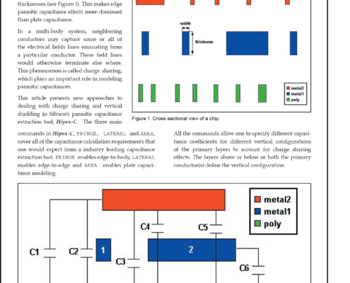
In deep submicron technology, conduction layers have widths much smaller than their thicknesses (see Figure 1). This makes edge parasitic capacitance effects more dominant than plate capacitance.
In a multi-body system, neighboring conductors may capture some or all of the electrical fields lines emanating from a particular conductor. These field lines would otherwise terminate else where. This phenomenon is called charge sharing, which plays an important role in modeling parasitic capacitances.
Capacitance Coupling Calculation of IPS mode TFT-LCD Using Clever
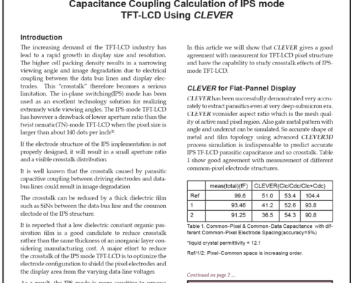
The increasing demand of the TFT-LCD industry has lead to a rapid growth in display size and resolution. The higher cell packing density results in a narrowing viewing angle and image degradation due to electrical coupling between the data bus lines and display electrodes. This “crosstalk” therefore becomes a serious limitation. The in-plane switching(IPS) mode has been used as an excellent technology solution for realizing extremely wide viewing angles.
Can Athena get the STRESS in Compound Advanced material?
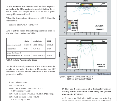
Q: Can ATHENA get the STRESS in Compound Advanced material?
A: The ATHENA STRESS command has been augmented to allow the 2 Dimensional stress distribution. To get the STRESS, the simple SiO2/GaAs/AlGaAs Optical waveguide was considered.
Simulating Selective and Non-Selective Epitaxy Over Oxide Isolated Regions Using Athena
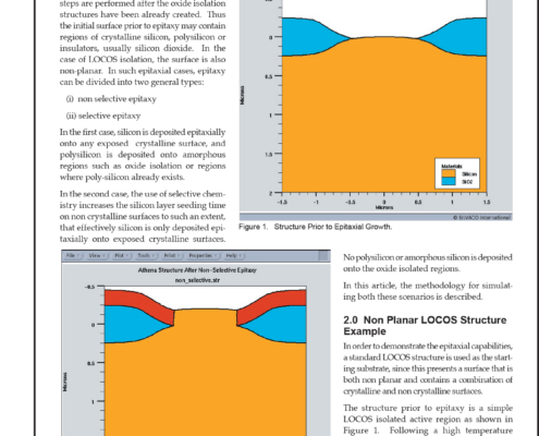
In certain cases, most notably in modern bipolar and SiGe HBT structures, epitaxial steps are performed after the oxide isolation structures have been already created. Thus the initial surface prior to epitaxy may contain regions of crystalline silicon, polysilicon or insulators, usually silicon dioxide. In the case of LOCOS isolation, the surface is also non-planar.
Process and Device Simulation of Field Emission Microtrides
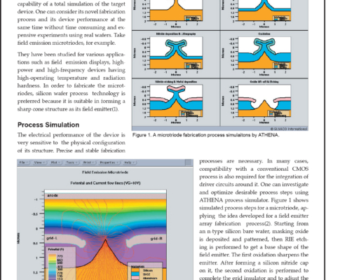
One of the most beneficial merits of computer-based experiment using TCAD lies in its capability of a total simulation of the target device. One can consider its novel fabrication process and its device performance at the same time without time consuming and expensive experiments using real wafers. Take field emission microtriodes, for example.
Pending Issues in the Modeling of Concentrator Solar Cells
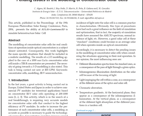
The modelling of concentrator solar cells for real conditions of operation inside optical concentrators is a subject almost untreated. Consequently, this work highlights the main specific situations that should be included in a realistic modelling. The results of a 2-D modelling applied to the case of a 1000 sun GaAs concentrator solar cell inside a TIR-R concentrator are presented. The necessity of going towards a 3-D modelling is also stated. This task is being carried out now at IES-UPM. Keywords: concentrator cells, modelling, III-V semiconductors.
How can I view a Foundry DRC run in Expert?
Q: How can I view a Foundry DRC run in Expert?
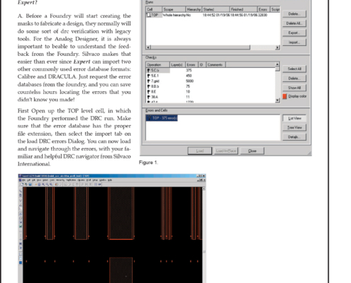
A: Before a Foundry will start creating the masks to fabricate a design, they normally will do some sort of drc verification with legacy tools. For the Analog Designer, it is always important to beable to understand the feedback from the Foundry. Silvaco makes that easier than ever since Expert can import two other commonly used error database formats: Calibre and DRACULA. Just request the error databases from the foundry, and you can save countelss hours locating the errors that you didn’t know you made!
Using Expert’s Pcell Feature to Generate Complex Shaped Layers
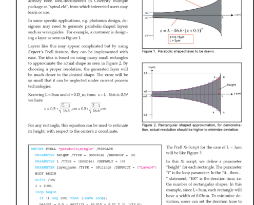
One of the strengths of Expert is to generate complex shaped layers such as spiral inductors, parabolic waveguides, etc. For the case of the spiral inductor, it has already been well-documented in CELEBRITY example package as “spiral.eld”, from which interested users may learn or use.
