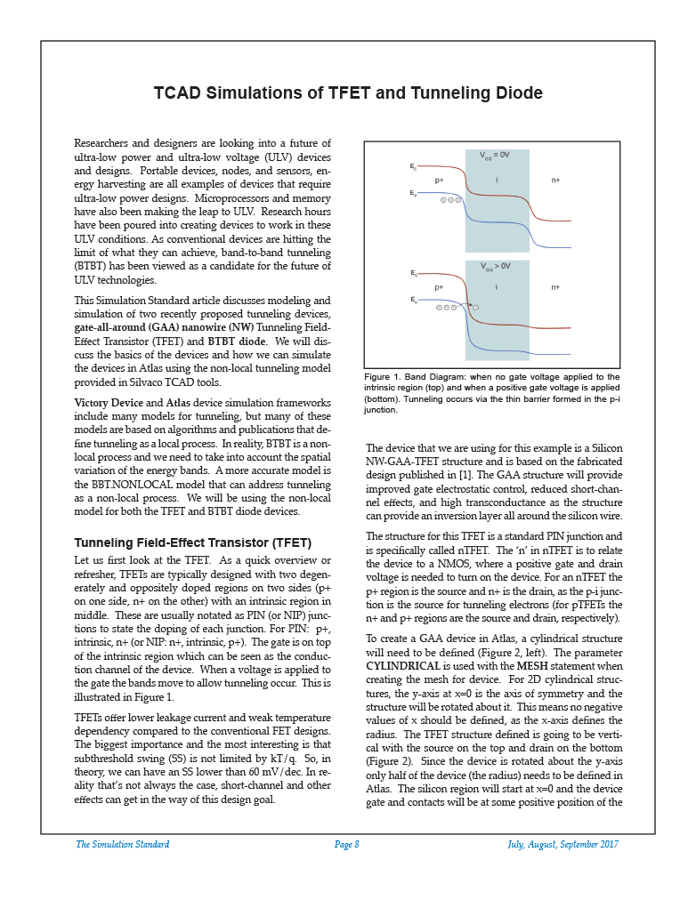
Researchers and designers are looking into a future of ultra-low power and ultra-low voltage (ULV) devices and designs. Portable devices, nodes, and sensors, energy harvesting are all examples of devices that require ultra-low power designs. Microprocessors and memory have also been making the leap to ULV. Research hours have been poured into creating devices to work in these ULV conditions. As conventional devices are hitting the limit of what they can achieve, band-to-band tunneling (BTBT) has been viewed as a candidate for the future of ULV technologies.
https://silvaco.com/wp-content/uploads/2020/03/simstd_Q3_2017_a3-1.jpg1012782Ingrid Schwarz/wp-content/uploads/2019/11/silvaco-logo.pngIngrid Schwarz2017-07-01 22:42:122021-07-08 18:14:52TCAD Simulations of TFET and Tunneling Diode
TFT panels have already gained their undisputable reputation in a variety of professional and commercial applications. High quality, ease of customization, and comparably low manufacturing costs position these panels as an attractive solution offered by standard and custom color display industry. To accomplish the goals set by ever increasing quality standards, TFT panel circuits constantly expand their functionality, add new features. This process naturally leads to an increased complexity of the display systems and, as a consequence, is accompanied by a strong demand for higher operating speeds. Traditionally, implementation of the solutions satisfying these tough requirements in the industry is accompanied by device feature size reduction and by placing more and more elements of the system chips. Modern TFT panel circuits contain millions of active and passive devices and their chip sizes continue to grow with every new generation.
https://silvaco.com/wp-content/uploads/2020/03/TFT_SmartSpice_fig1.jpg417550Ingrid Schwarz/wp-content/uploads/2019/11/silvaco-logo.pngIngrid Schwarz2017-07-01 19:44:552021-07-08 18:14:53TFT Panel Simulation Using SmartSpice Pro
Compared with regular MOSFET devices, the body bias effect in HVMOS is usually more pronounced. In addition to the regular threshold voltage increase with body bias, the LDD region of the HVMOS typically also has a significant body bias dependence. Also, the VBS dependence of mobility degradation with the transversal electric field needs to be taken into account. Due to these particularities, modeling of HVMOS devices with body contact requires careful consideration of body bias dependencies. Semi-empirical compact models make use of extra model parameters in order to achieve the needed body bias dependence accuracy. In the case of physics-based compact models, such as HiSIM_HV2, the effect of body bias can be naturally and accurately considered, with very few such extra parameters.
https://silvaco.com/wp-content/uploads/2020/02/simstd_Q2_2017_a4-1.jpg1012782Ingrid Schwarz/wp-content/uploads/2019/11/silvaco-logo.pngIngrid Schwarz2017-04-01 18:27:142021-07-08 18:14:53Model Extraction for Body-Biased XDMOS Devices
3D TFT analysis has been getting lots of attention due to issues caused by 3D effects such as the edge effect on the TFT characteristics. The presence of an enhanced electrical field at the edges of the channel has been reported to affect the TFT characteristics in the sub-threshold region [1-2]. The hump characteristics observed in poly-Si TFTs or crystalline metal-oxide-semiconductor-field-effect transistors (MOSFETs) is often explained by this edge effect and is considered to be related to the shape of the edge.
https://silvaco.com/wp-content/uploads/2020/02/simstd_Q2_2017_a3.jpg1012782Ingrid Schwarz/wp-content/uploads/2019/11/silvaco-logo.pngIngrid Schwarz2017-04-01 18:23:472021-07-08 18:14:54Edge Effect Analysis on TFT Devices Using 3D Numerical Simulation
Dual-Gate Thin Film Transistors (DGTFTs) are often used in pixel driver and peripheral circuits for liquid crystal displays. This is because of the reduction of the gate-off state leakage current as well as the kink effect [1,2]. Recently it has been also necessary to consider the problems caused by 3D effects such as the IV characteristics hump effect [3] and leakage current at the edge of the active region [4,5]. This requires 3D simulation of DGTFT characteristics in a reasonable time. However, simulation of DGTFTs is generally difficult, particularly in 3D, because of the electrical floating region between the dual TFTs. This region can cause difficult convergence when calculating the gate-off state characteristics including the Gate-Induced Drain Leakage (GIDL) current. In this article, we demonstrate that our 3D TCAD simulation framework, Victory, can simulate a normal DGTFT and an L-shape DGTFT [2] in 3D accurately, robustly and in a reasonable simulation time.
https://silvaco.com/wp-content/uploads/2020/02/simstd_Q2_2017_a2.jpg1012782Ingrid Schwarz/wp-content/uploads/2019/11/silvaco-logo.pngIngrid Schwarz2017-04-01 18:17:162021-07-08 18:16:293D Simulation of Dual-Gate Thin Film Transistors
The planar bulk Si metal-oxide semiconductor field-effect transistor (MOSFET) has reached its scaling limit due to various short channel effects (SCE). With 20 nm advanced planar technology, the source and drain encroached into channel resulting in off state leakage current. Tri gate FinFET devices have already replaced conventional planar MOSFETs for 14nm and beyond due to their superior control over the channel resulting in lower values of subthreshold swing (SS) and reduced drain induced barrier lowering (DIBL). Nevertheless, gate induced drain leakage is found to be the limiting factor in achieving ultralow (<100pA/um) values of IOFF. In this work, we have studied the effect of fin thickness on subthreshold characteristics of bulk nFinFET using three dimensional simulation.
https://silvaco.com/wp-content/uploads/2020/02/simstd_Q2_2017_a1.jpg1012782Ingrid Schwarz/wp-content/uploads/2019/11/silvaco-logo.pngIngrid Schwarz2017-04-01 18:10:392021-07-08 18:16:29Effect of Fin Thickness on Subthreshold Characteristics of 10 nm FinFETs Using 3D TCAD
Silvaco uses cookies to improve your user experience and to provide you with content we believe will be of interest to you. Learn detailed information on Privacy Policy. By using this website, you consent to the use of our cookies.
We may request cookies to be set on your device. We use cookies to let us know when you visit our websites, how you interact with us, to enrich your user experience, and to customize your relationship with our website.
Click on the different category headings to find out more. You can also change some of your preferences. Note that blocking some types of cookies may impact your experience on our websites and the services we are able to offer.
Essential Website Cookies
These cookies are strictly necessary to provide you with services available through our website and to use some of its features.
Because these cookies are strictly necessary to deliver the website, refuseing them will have impact how our site functions. You always can block or delete cookies by changing your browser settings and force blocking all cookies on this website. But this will always prompt you to accept/refuse cookies when revisiting our site.
We fully respect if you want to refuse cookies but to avoid asking you again and again kindly allow us to store a cookie for that. You are free to opt out any time or opt in for other cookies to get a better experience. If you refuse cookies we will remove all set cookies in our domain.
We provide you with a list of stored cookies on your computer in our domain so you can check what we stored. Due to security reasons we are not able to show or modify cookies from other domains. You can check these in your browser security settings.
Google Analytics Cookies
These cookies collect information that is used either in aggregate form to help us understand how our website is being used or how effective our marketing campaigns are, or to help us customize our website and application for you in order to enhance your experience.
If you do not want that we track your visit to our site you can disable tracking in your browser here:
Other external services
We also use different external services like Google Webfonts, Google Maps, and external Video providers. Since these providers may collect personal data like your IP address we allow you to block them here. Please be aware that this might heavily reduce the functionality and appearance of our site. Changes will take effect once you reload the page.
Google Webfont Settings:
Google Map Settings:
Google reCaptcha Settings:
Vimeo and Youtube video embeds:
Other cookies
The following cookies are also needed - You can choose if you want to allow them:
Privacy Policy
You can read about our cookies and privacy settings in detail on our Privacy Policy Page.

 https://silvaco.com/wp-content/uploads/2020/03/simstd_Q3_2017_a3-1.jpg
1012
782
Ingrid Schwarz
/wp-content/uploads/2019/11/silvaco-logo.png
Ingrid Schwarz2017-07-01 22:42:122021-07-08 18:14:52TCAD Simulations of TFET and Tunneling Diode
https://silvaco.com/wp-content/uploads/2020/03/simstd_Q3_2017_a3-1.jpg
1012
782
Ingrid Schwarz
/wp-content/uploads/2019/11/silvaco-logo.png
Ingrid Schwarz2017-07-01 22:42:122021-07-08 18:14:52TCAD Simulations of TFET and Tunneling Diode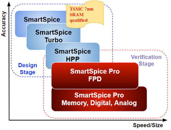 https://silvaco.com/wp-content/uploads/2020/03/TFT_SmartSpice_fig1.jpg
417
550
Ingrid Schwarz
/wp-content/uploads/2019/11/silvaco-logo.png
Ingrid Schwarz2017-07-01 19:44:552021-07-08 18:14:53TFT Panel Simulation Using SmartSpice Pro
https://silvaco.com/wp-content/uploads/2020/03/TFT_SmartSpice_fig1.jpg
417
550
Ingrid Schwarz
/wp-content/uploads/2019/11/silvaco-logo.png
Ingrid Schwarz2017-07-01 19:44:552021-07-08 18:14:53TFT Panel Simulation Using SmartSpice Pro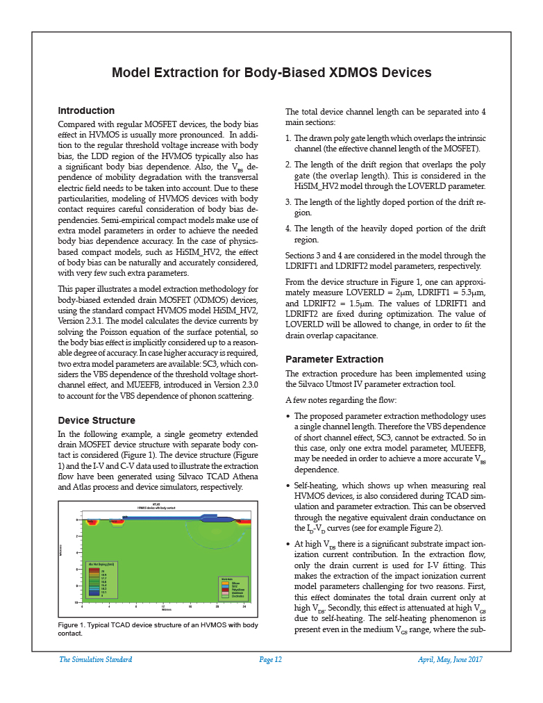 https://silvaco.com/wp-content/uploads/2020/02/simstd_Q2_2017_a4-1.jpg
1012
782
Ingrid Schwarz
/wp-content/uploads/2019/11/silvaco-logo.png
Ingrid Schwarz2017-04-01 18:27:142021-07-08 18:14:53Model Extraction for Body-Biased XDMOS Devices
https://silvaco.com/wp-content/uploads/2020/02/simstd_Q2_2017_a4-1.jpg
1012
782
Ingrid Schwarz
/wp-content/uploads/2019/11/silvaco-logo.png
Ingrid Schwarz2017-04-01 18:27:142021-07-08 18:14:53Model Extraction for Body-Biased XDMOS Devices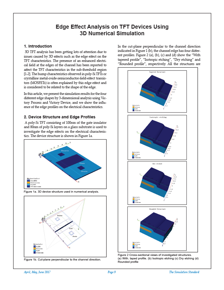 https://silvaco.com/wp-content/uploads/2020/02/simstd_Q2_2017_a3.jpg
1012
782
Ingrid Schwarz
/wp-content/uploads/2019/11/silvaco-logo.png
Ingrid Schwarz2017-04-01 18:23:472021-07-08 18:14:54Edge Effect Analysis on TFT Devices Using 3D Numerical Simulation
https://silvaco.com/wp-content/uploads/2020/02/simstd_Q2_2017_a3.jpg
1012
782
Ingrid Schwarz
/wp-content/uploads/2019/11/silvaco-logo.png
Ingrid Schwarz2017-04-01 18:23:472021-07-08 18:14:54Edge Effect Analysis on TFT Devices Using 3D Numerical Simulation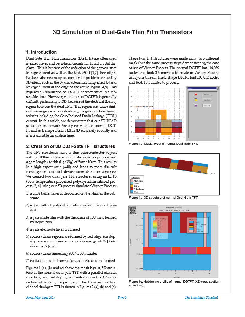 https://silvaco.com/wp-content/uploads/2020/02/simstd_Q2_2017_a2.jpg
1012
782
Ingrid Schwarz
/wp-content/uploads/2019/11/silvaco-logo.png
Ingrid Schwarz2017-04-01 18:17:162021-07-08 18:16:293D Simulation of Dual-Gate Thin Film Transistors
https://silvaco.com/wp-content/uploads/2020/02/simstd_Q2_2017_a2.jpg
1012
782
Ingrid Schwarz
/wp-content/uploads/2019/11/silvaco-logo.png
Ingrid Schwarz2017-04-01 18:17:162021-07-08 18:16:293D Simulation of Dual-Gate Thin Film Transistors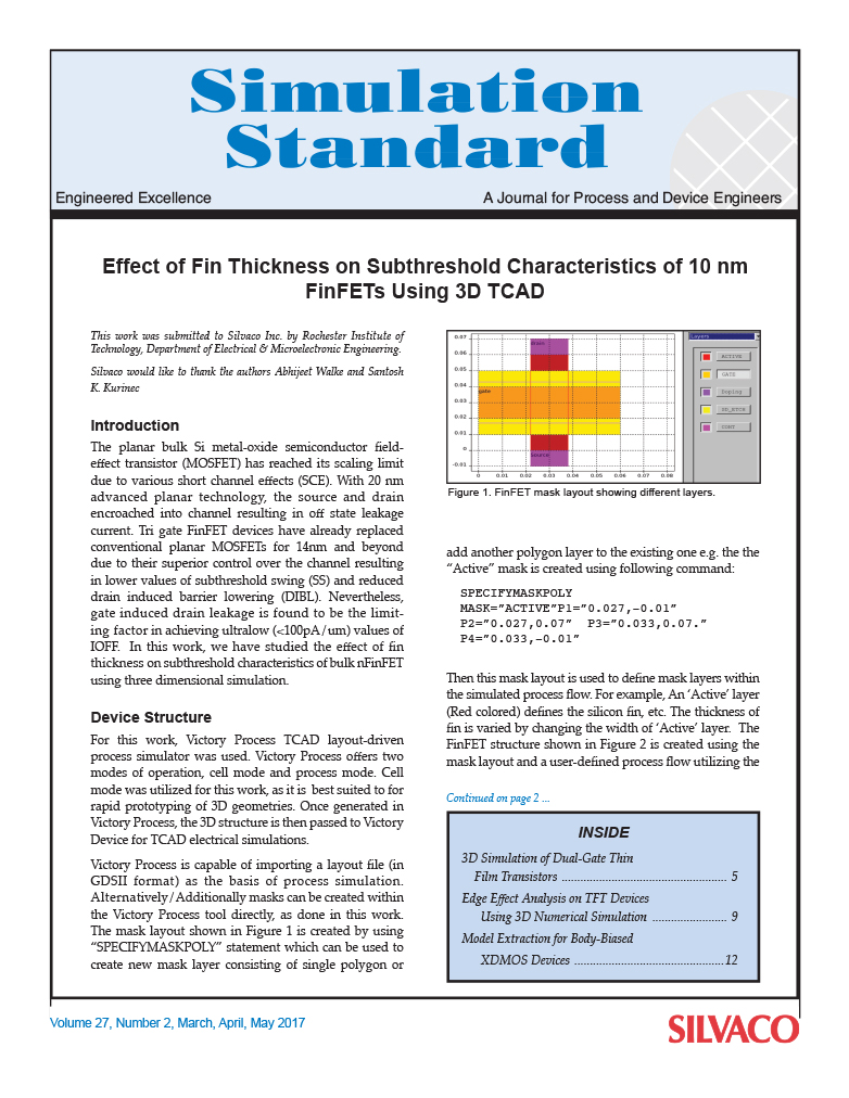 https://silvaco.com/wp-content/uploads/2020/02/simstd_Q2_2017_a1.jpg
1012
782
Ingrid Schwarz
/wp-content/uploads/2019/11/silvaco-logo.png
Ingrid Schwarz2017-04-01 18:10:392021-07-08 18:16:29Effect of Fin Thickness on Subthreshold Characteristics of 10 nm FinFETs Using 3D TCAD
https://silvaco.com/wp-content/uploads/2020/02/simstd_Q2_2017_a1.jpg
1012
782
Ingrid Schwarz
/wp-content/uploads/2019/11/silvaco-logo.png
Ingrid Schwarz2017-04-01 18:10:392021-07-08 18:16:29Effect of Fin Thickness on Subthreshold Characteristics of 10 nm FinFETs Using 3D TCAD