Process Flow Simulation and Manufacture of Variable RF MEMS Capacitors
Yong Qing Fu, Jack Luo, Stuart Milne, Andrew Flewitt
Engineering Department, University of Cambridge, Cambridge UK
Ahmed Nejim
Silvaco, St Ives, Cambridgeshire PE27 5JL, UK
Introduction
The application of microelectromechanical systems (MEMS) to radio-frequency (RF)/microwave systems is on the verge of revolutionizing wireless communications, mainly in the areas of wireless personal communication systems, wireless local area networks, satellite communications, and automotive electronics [1]. In this article we present a brief introduction to the design and fabrication effort at the Engineering Department, University of Cambridge, which is focused on variable RF capacitor MEMS structures. Silvaco 2D/3D process simulation was used to simulate the process flow and reproduce the obtained structures as a first step to future process flow and structure designs.
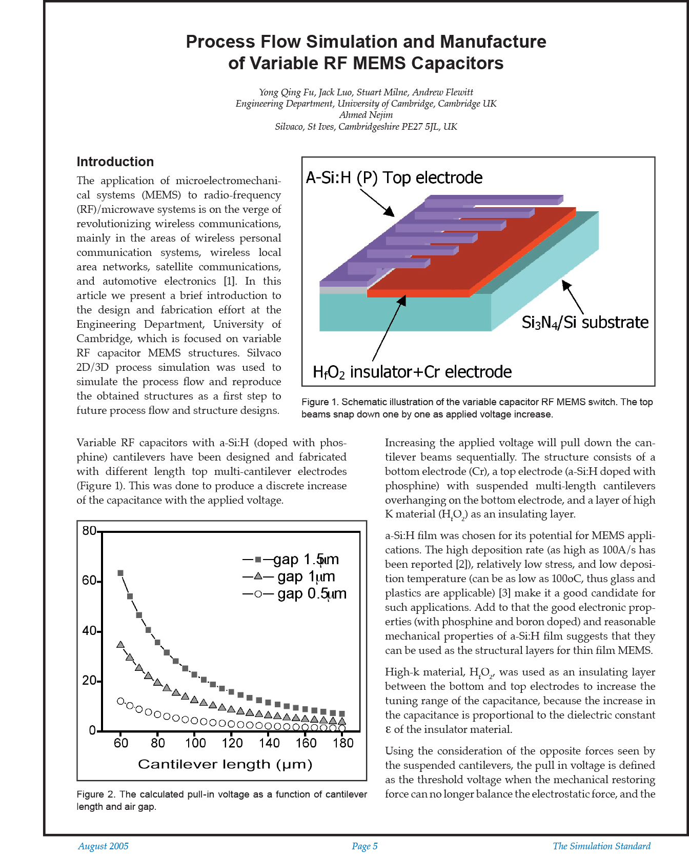
Variable RF capacitors with a-Si:H (doped with phosphine) cantilevers have been designed and fabricated with different length top multi-cantilever electrodes (Figure 1). This was done to produce a discrete increase of the capacitance with the applied voltage. Increasing the applied voltage will pull down the cantilever beams sequentially. The structure consists of a bottom electrode (Cr), a top electrode (a-Si:H doped with phosphine) with suspended multi-length cantilevers overhanging on the bottom electrode, and a layer of high K material (HfO2) as an insulating layer.
a-Si:H film was chosen for its potential for MEMS applications. The high deposition rate (as high as 100A/s has been reported [2]), relatively low stress, and low deposition temperature (can be as low as 100oC, thus glass and plastics are applicable) [3] make it a good candidate for such applications. Add to that the good electronic properties (with phosphine and boron doped) and reasonable mechanical properties of a-Si:H film suggests that they can be used as the structural layers for thin film MEMS.
High-k material, HfO2, was used as an insulating layer between the bottom and top electrodes to increase the tuning range of the capacitance, because the increase in the capacitance is proportional to the dielectric constant e of the insulator material.
Using the consideration of the opposite forces seen by the suspended cantilevers, the pull in voltage is defined as the threshold voltage when the mechanical restoring force can no longer balance the electrostatic force, and the cantilever abruptly falls to the bottom contact. The calculation of these forces produced the following pull in voltage data as a function of cantilever length and the separating gap.


