Schematic Driven Layout
Introduction
Expert schematic driven layout (SDL) is a CAD tool which increases the productivity of layout design by automating cell generation and providing visual cues to assist the wiring process. In the current implementation, schematic driven layout is used to automatically create IC layouts based on information from a netlist. Cell instances are created from existing cells. P-cells are instanced with parameters from the netlist file. Schematic driven layout automatically transfers net names, instance names and connectivity information from netlist to the layout. Automatic instantiation of cells with built-in connectivity support dramatically speeds up layout designer’s productivity and accuracy.
Operation Flow
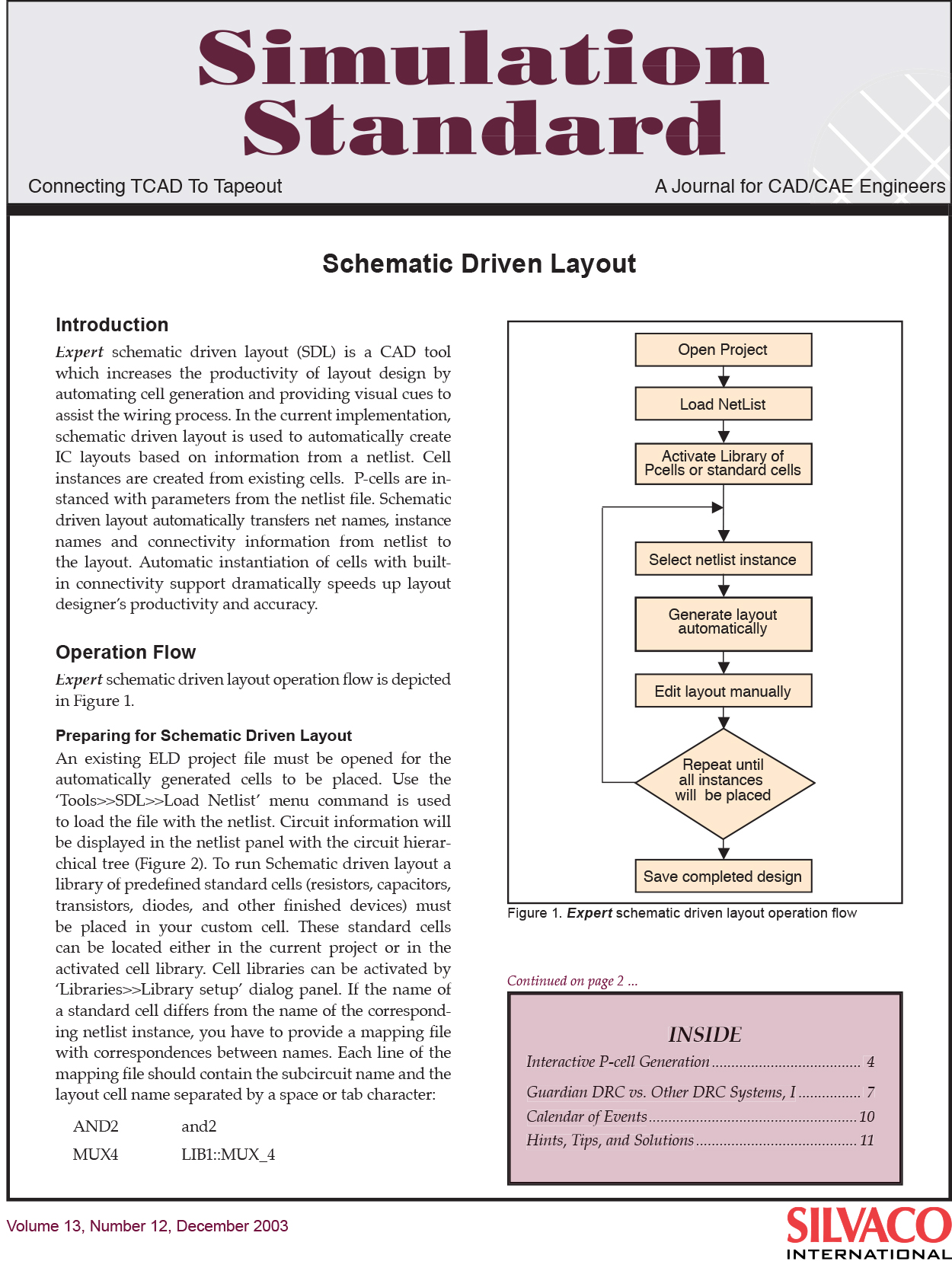
Expert schematic driven layout operation flow is depicted in Figure 1.
Preparing for Schematic Driven Layout
An existing ELD project file must be opened for the automatically generated cells to be placed. Use the ‘Tools>>SDL>>Load Netlist’ menu command is used to load the file with the netlist. Circuit information will be displayed in the netlist panel with the circuit hierarchical tree (Figure 2). To run Schematic driven layout a library of predefined standard cells (resistors, capacitors, transistors, diodes, and other finished devices) must be placed in your custom cell. These standard cells can be located either in the current project or in the activated cell library. Cell libraries can be activated by ‘Libraries>>Library setup’ dialog panel. If the name of a standard cell differs from the name of the corresponding netlist instance, you have to provide a mapping file with correspondences between names. Each line of the mapping file should contain the subcircuit name and the layout cell name separated by a space or tab character:


