IGBT Switching Simulation Based on the Double-Pulse Method
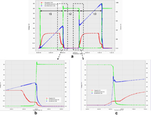 Minimizing switching losses remains a significant challenge for power devices. The standard method for measuring switching parameters and evaluating the dynamic behavior of Si, SiC, and GaN MOSFETs and IGBTs is the Double Pulse Test (DPT) [1]. DPT helps determine switching times, switching losses, and ensures proper switching behavior. Figure 1 shows a typical circuit diagram for the DPT. The device under test (DUT) consists of two devices: the lower IGBT and the upper Diode. Inductor load L is used to replicate real circuit conditions. Leakage inductance Lσ and stray capacity Cσ are also included in the circuit. Figure 2 represents the standards to measure switching time and switching loss for an IGBT. Further information can be found in the datasheet of a power device.
This article introduces a DPT-based simulation method to perform the transient switching characteristics of an IGBT device. It also provides standard templates for power device switching characteristics and performance assessment using Silvaco TCAD simulation tools. The deck used for this article can be found in Silicon_Power_ex17 of the 2024 Baseline.


