Simulation Standard
Technical Journal
A Journal for Process and Device Engineers
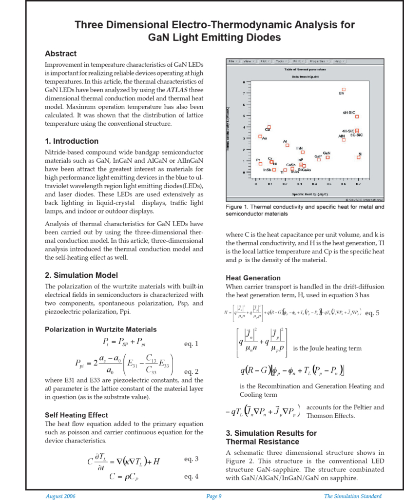
Three Dimensional Electro-Thermodynamic Analysis for GaN Light Emitting Diodes
Abstract
Improvement in temperature characteristics of GaN LEDs is important for realizing reliable devices operating at high temperatures. In this article, the thermal characteristics of GaN LEDs have been analyzed by using the ATLAS three dimensional thermal conduction model and thermal heat model. Maximum operation temperature has also been calculated. It was shown that the distribution of lattice temperature using the conventional structure.
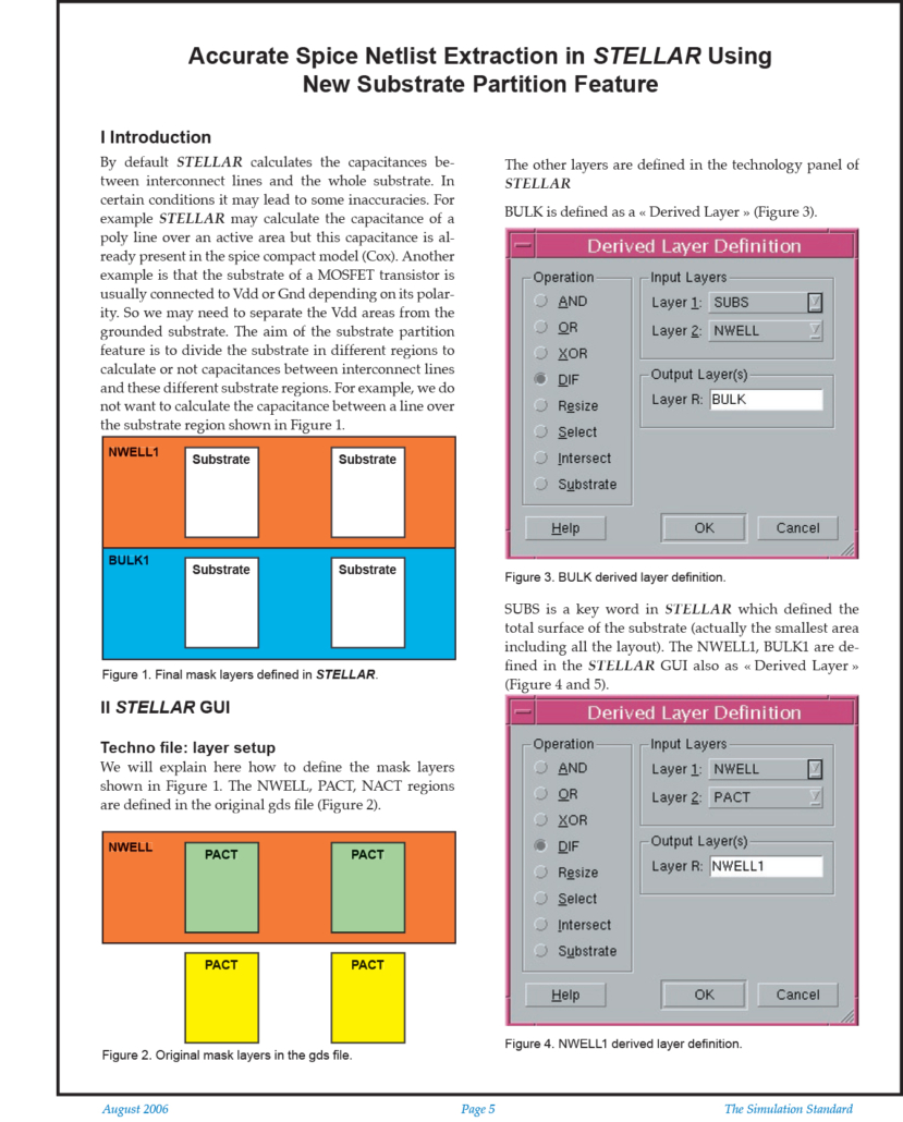
Accurate Spice Netlist Extraction in Stellar Using New Substrate Partition Feature
Introduction
By default STELLAR calculates the capacitances between interconnect lines and the whole substrate. In certain conditions it may lead to some inaccuracies. For example STELLAR may calculate the capacitance of a poly line over an active area but this capacitance is already present in the spice compact model (Cox). Another example is that the substrate of a MOSFET transistor is usually connected to Vdd or Gnd depending on its polarity.
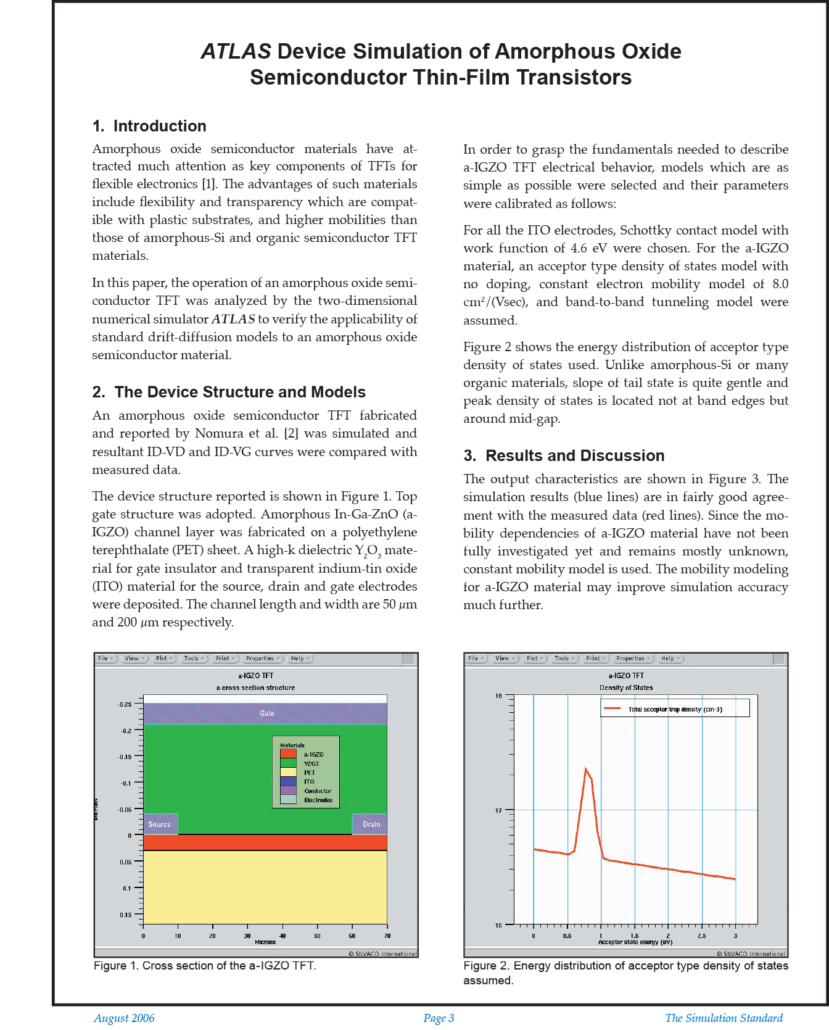
Atlas Device Simulation of Amorphous Oxide Semiconductor Thin-Film Transistors
1. Introduction
Amorphous oxide semiconductor materials have attracted much attention as key components of TFTs for flexible electronics [1]. The advantages of such materials include flexibility and transparency which are compatible with plastic substrates, and higher mobilities than those of amorphous-Si and organic semiconductor TFT materials.
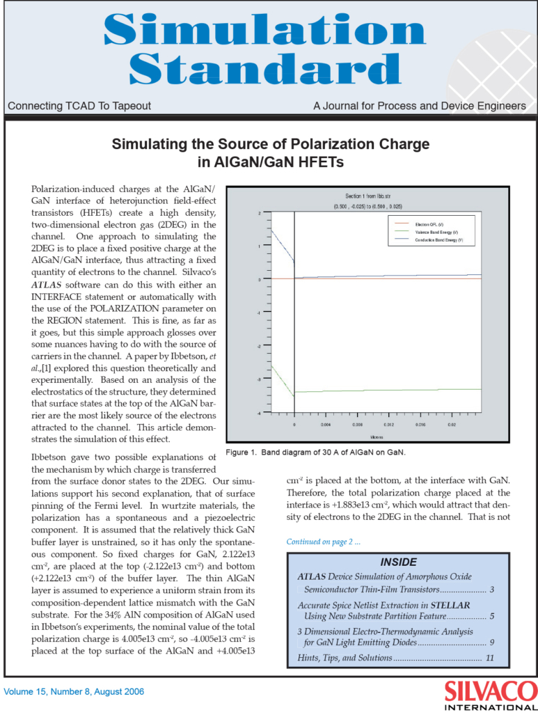
Simulating the Source of Polarization Charge in AlGaN/GaN HFETs
Polarization-induced charges at the AlGaN/GaN interface of heterojunction field-effect transistors (HFETs) create a high density, two-dimensional electron gas (2DEG) in the channel. One approach to simulating the 2DEG is to place a fixed positive charge at the AlGaN/GaN interface, thus attracting a fixed quantity of electrons to the channel. Silvaco’s ATLAS software can do this with either an INTERFACE statement or automatically with the use of the POLARIZATION parameter on the REGION statement. This is fine, as far as it goes, but this simple approach glosses over some nuances having to do with the source of carriers in the channel. A paper by Ibbetson, et al.,[1] explored this question theoretically and experimentally.
Interconnect Parasitic Extraction of BiCMOS Cell Using Silvaco Clever
Interconnect parasitic effects play a very important role in modern integrated circuit design, especially for digital circuit. This article presents how a cell level BiCMOS nand gate is extracted with R (resistances) and C (capacitances). The extracted RC result is then back-annotated into SPICE netlist for POST verification purpose. We used the Silvaco product, CLEVER which is a highly accurate 3D process interconnect RC extractor.
Evaluating of the Avalanche Failure of Power MOSFETs using Atlas
Introduction
Power MOSFETs are widely used with an inductive load for S/W power supplies, DC-DC converters, and so on. But due to high frequency operation, the surge voltage applied to the MOSFETs at turn-off depends on the inductance and parasitic inductance in the circuit. For some operation modes, the pulse width for the turn-on or off will be very short, and the device fails due to the short surge period.

