Simulation Standard
Silvaco面向半导体工艺和器件仿真工程师推出的技术刊物
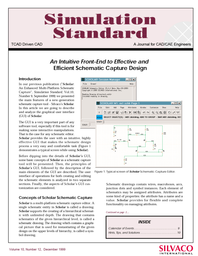
An Intuitive Front-End to Effective and Efficient Schematic Capture Design
In our previous publication ("Scholar: An Enhanced Multi-Platform Schematic Capture", Simulation Standard, Vol.10, Number 9, September 1999) we presented the main features of a new-generation schematic capture tool - Silvaco's Scholar. In this article we are going to describe and analyze the graphical user interface (GUI) of Scholar.
Hints & Tips November 1999
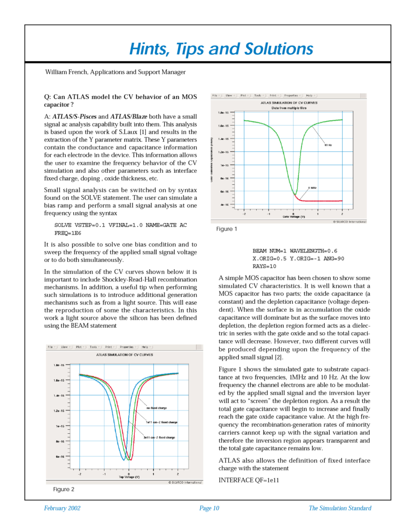
A: ATLAS/S-Pisces and ATLAS/Blaze both have a small signal ac analysis capability built into them. This analysis is based upon the work of S.Laux [1] and results in the extraction of the Y parameter matrix. These Y parameters contain the conductance and capacitance information for each electrode in the device. This information allows the user to examine the frequency behavior of the CV simulation and also other parameters such as interface fixed charge, doping , oxide thickness, etc.
Modeling Bidirectional Thyristors Using ATLAS
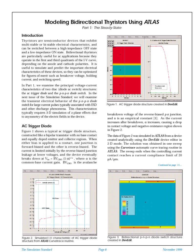
Thyristors are semiconductor devices that exhibit multi-stable or bi-stable electrical characteristics, and can be switched between a high-impedance OFF state and a low-impedance ON state. Bidirectional thyristors are particularly useful for ac applications because they operate in the first and third quadrants of the I-V curve, depending on the anode and cathode polarities. It is useful to simulate and predict the important electrical characteristics of these devices, so they can be optimized for figures-of-merit such as breakover voltage, holding current, and switching speed.
Modelling Tunneling Currents in Ultra Thin Oxides
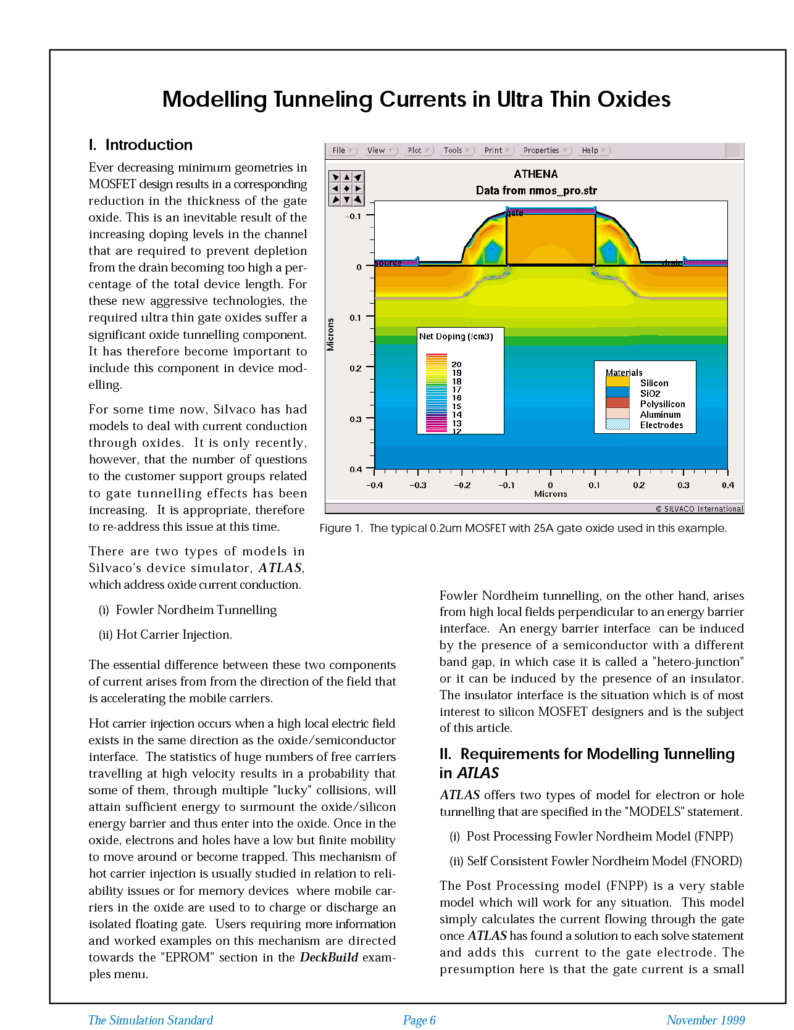
Ever decreasing minimum geometries in MOSFET design results in a corresponding reduction in the thickness of the gate oxide. This is an inevitable result of the increasing doping levels in the channel that are required to prevent depletion from the drain becoming too high a percentage of the total device length. For these new aggressive technologies, the required ultra thin gate oxides suffer a significant oxide tunnelling component. It has therefore become important to include this component in device modelling.
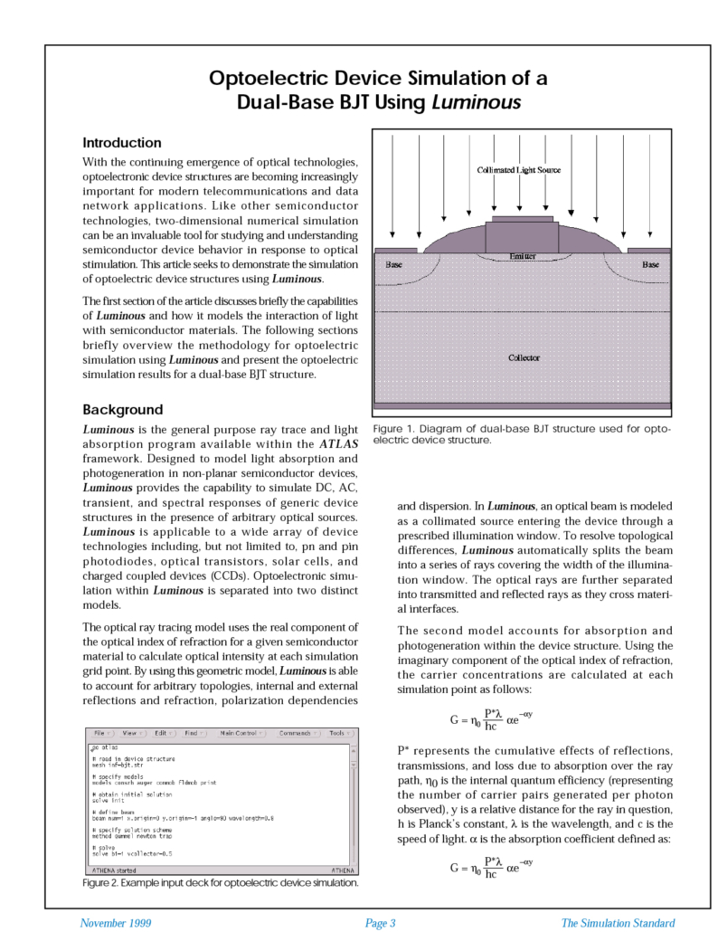
Optoelectric Device Simulation of a Dual-Base BJT Using Luminous
With the continuing emergence of optical technologies, optoelectronic device structures are becoming increasingly important for modern telecommunications and data network applications. Like other semiconductor technologies, two-dimensional numerical simulation can be an invaluable tool for studying and understanding semiconductor device behavior in response to optical stimulation. This article seeks to demonstrate the simulation of optoelectric device structures using Luminous.
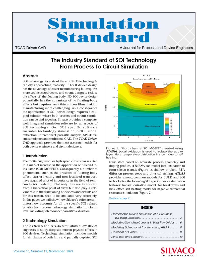
The Industry Standard of SOI Technology From Process To Circuit Simulation
SOI technology for state of the art CMOS technology is rapidly approaching maturity. PD-SOI device design has the advantage of easier manufacturing but requires more sophisticated device and circuit design to reduce the effects of the floating-body. FD-SOI device design potentially has the advantage of no floating-body effects but requires very thin silicon films making manufacturing more challenging. As a consequence the optimization of SOI device design requires a coupled solution where both process and circuit simulation can be tied together. Silvaco provides a complete, well integrated simulation software for all aspects of SOI technology. Our SOI specific software includes technology simulation, SPICE model extraction, interconnect parasitic analysis, SPICE circuit simulation and traditional CAD. The TCAD Driven CAD approach provides the most accurate models for both device engineers and circuit designers.

