
Simulation Standard Technical Journal
A Journal for Process and Device Engineers
 https://silvaco.com/wp-content/uploads/2020/03/simstd_Q4_2014_a2.jpg
1012
782
Ingrid Schwarz
/wp-content/uploads/2019/11/silvaco-logo.png
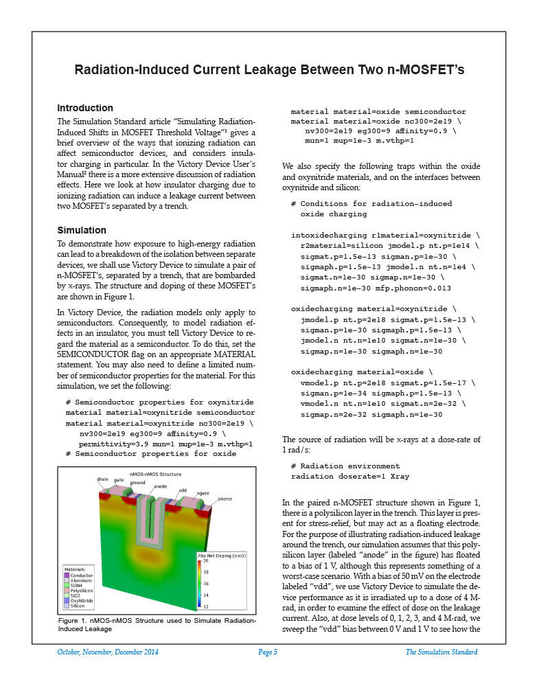
Ingrid Schwarz2014-10-01 16:13:312020-12-22 12:14:21Radiation-Induced Current Leakage Between Two n-MOSFET’s
https://silvaco.com/wp-content/uploads/2020/03/simstd_Q4_2014_a2.jpg
1012
782
Ingrid Schwarz
/wp-content/uploads/2019/11/silvaco-logo.png
Ingrid Schwarz2014-10-01 16:13:312020-12-22 12:14:21Radiation-Induced Current Leakage Between Two n-MOSFET’s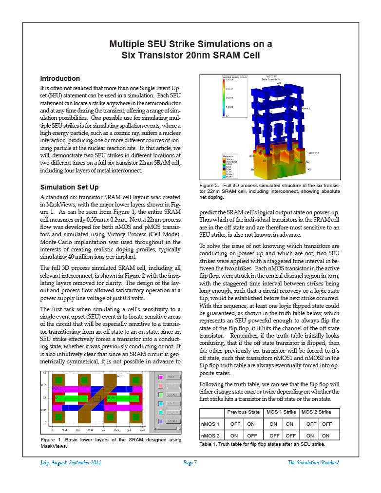 https://silvaco.com/wp-content/uploads/2020/03/simstd_Q3_2014_a2.jpg
1012
782
Ingrid Schwarz
/wp-content/uploads/2019/11/silvaco-logo.png
Ingrid Schwarz2014-07-01 20:14:592020-12-22 12:48:48Multiple SEU Strike Simulations on a Six Transistor 20nm SRAM Cell
https://silvaco.com/wp-content/uploads/2020/03/simstd_Q3_2014_a2.jpg
1012
782
Ingrid Schwarz
/wp-content/uploads/2019/11/silvaco-logo.png
Ingrid Schwarz2014-07-01 20:14:592020-12-22 12:48:48Multiple SEU Strike Simulations on a Six Transistor 20nm SRAM Cell https://silvaco.com/wp-content/uploads/2020/03/simstd_Q3_2014_a1.jpg
1012
782
Ingrid Schwarz
/wp-content/uploads/2019/11/silvaco-logo.png
Ingrid Schwarz2014-07-01 20:08:292020-12-22 10:12:41The Physics of Single Event Burnout (SEB)
https://silvaco.com/wp-content/uploads/2020/03/simstd_Q3_2014_a1.jpg
1012
782
Ingrid Schwarz
/wp-content/uploads/2019/11/silvaco-logo.png
Ingrid Schwarz2014-07-01 20:08:292020-12-22 10:12:41The Physics of Single Event Burnout (SEB) https://silvaco.com/wp-content/uploads/2020/03/simstd_Q3_2014_hints2.jpg
1012
782
Ingrid Schwarz
/wp-content/uploads/2019/11/silvaco-logo.png
Ingrid Schwarz2014-07-01 16:07:272020-12-22 16:44:44Hints, Tips, and Solutions – Types of 3D Delaunay Shape Refinement in Victory Process
https://silvaco.com/wp-content/uploads/2020/03/simstd_Q3_2014_hints2.jpg
1012
782
Ingrid Schwarz
/wp-content/uploads/2019/11/silvaco-logo.png
Ingrid Schwarz2014-07-01 16:07:272020-12-22 16:44:44Hints, Tips, and Solutions – Types of 3D Delaunay Shape Refinement in Victory Process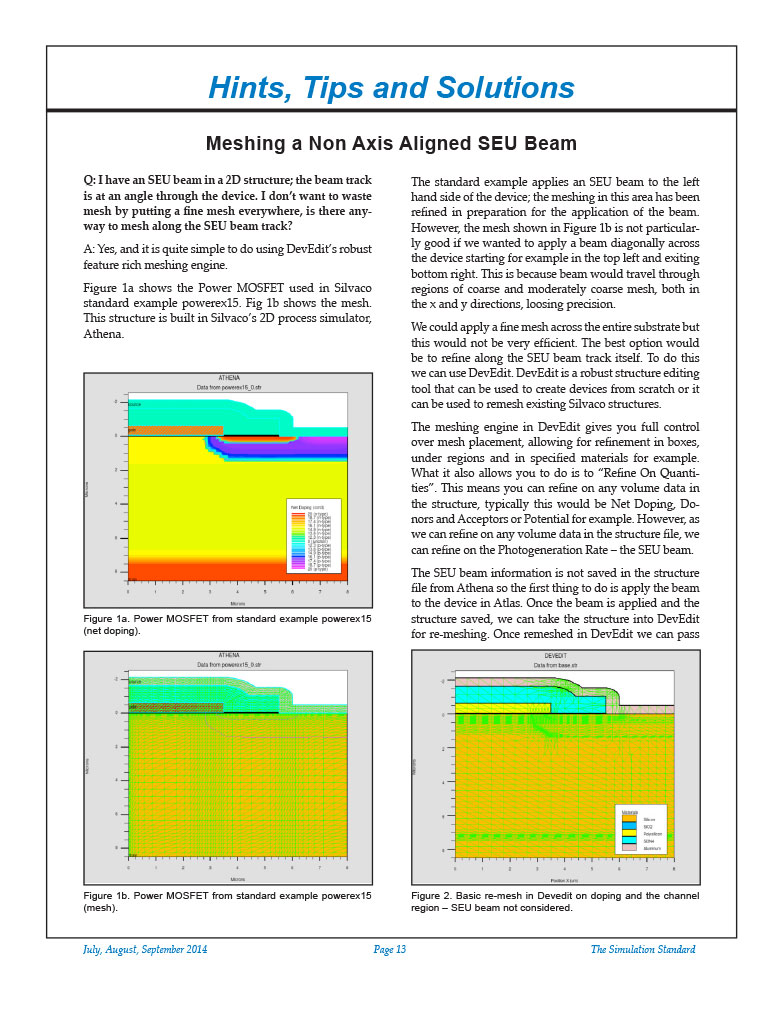 https://silvaco.com/wp-content/uploads/2020/03/simstd_Q3_2014_hints1.jpg
1012
782
Ingrid Schwarz
/wp-content/uploads/2019/11/silvaco-logo.png
Ingrid Schwarz2014-07-01 16:02:242021-01-22 14:28:38Hints, Tips and Solutions – Meshing a Non Axis Aligned SEU Beam
https://silvaco.com/wp-content/uploads/2020/03/simstd_Q3_2014_hints1.jpg
1012
782
Ingrid Schwarz
/wp-content/uploads/2019/11/silvaco-logo.png
Ingrid Schwarz2014-07-01 16:02:242021-01-22 14:28:38Hints, Tips and Solutions – Meshing a Non Axis Aligned SEU Beam https://silvaco.com/wp-content/uploads/2020/03/simstd_Q2_2014_hints2.jpg
1012
782
Ingrid Schwarz
/wp-content/uploads/2019/11/silvaco-logo.png
Ingrid Schwarz2014-04-01 19:41:272021-01-11 12:20:20Hints, Tips, and Solutions – Calculate Light Extraction Efficiency in an OLED or LED with Pure Optical Simulation
https://silvaco.com/wp-content/uploads/2020/03/simstd_Q2_2014_hints2.jpg
1012
782
Ingrid Schwarz
/wp-content/uploads/2019/11/silvaco-logo.png
Ingrid Schwarz2014-04-01 19:41:272021-01-11 12:20:20Hints, Tips, and Solutions – Calculate Light Extraction Efficiency in an OLED or LED with Pure Optical Simulation