Using Victory Process Open Model Interface to Customize Etch Emulation Model – Example: Mimicking Micro-Trenching Effect During Dry Etching of a Trench in Silicon Carbide
Introduction
Dry etching is commonly used in semiconductor processing to generate deep trenches with good anisotropy. Dry etching is applied to many semiconductor technologies including Advanced FinFETs, 3D NAND, and vertical Silicon and Silicon Carbide power devices. Within Victory Process, users can emulate etching (without physics) or enable more comprehensive physical etch models to perform physical etching in simulation. Either of these methods can be integrated into a process flow to produce a 2D or 3D TCAD structure, and then exported to Victory Device to perform electrical analysis.
While more physically accurate and insightful, physical etching can be computationally intensive and require more detailed calibration. Users may choose to opt for the simplicity of emulation, achieving device geometry of suitable accuracy. However, it is observed experimentally that dry etching can produce trenches with non-ideal geometry that can have deleterious effects on device electrical operation. These geometry flaws will not be captured by an emulation simulation model, which by its nature produces ideal geometry.
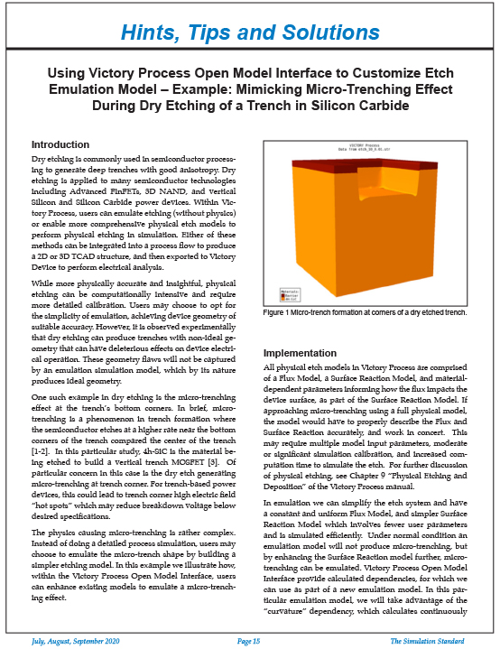
One such example in dry etching is the micro-trenching effect at the trench’s bottom corners. In brief, microtrenching is a phenomenon in trench formation where the semiconductor etches at a higher rate near the bottom corners of the trench compared the center of the trench [1-2]. In this particular study, 4h-SiC is the material being etched to build a vertical trench MOSFET [3]. Of particular concern in this case is the dry etch generating micro-trenching at trench corner. For trench-based power devices, this could lead to trench corner high electric field “hot spots” which may reduce breakdown voltage below
desired specifications.


